![]()
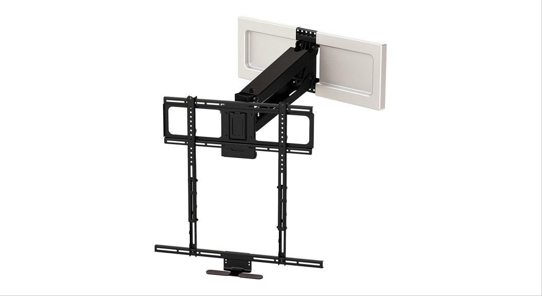
MM750 Installation Instructions
IMPORTANT SAFETY INSTRUCTIONS
SAVE THESE INSTRUCTIONS
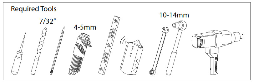
Please read this entire manual before you begin. Do not unpack any contents until you verify all requirements on PAGE 3. If you have any questions, visit MantelMount.com or call (800)-897-9755.
![]() WARNING!This product contains small parts that can be a choking hazard. Do not let children play with any of these small parts! Keep children away from the work area during installation.
WARNING!This product contains small parts that can be a choking hazard. Do not let children play with any of these small parts! Keep children away from the work area during installation.
![]() WARNING!Do not let small children operate, pull on, or hang from MantelMount. Do not operate MantelMount when anyone is near or behind the mount. MantelMount is very strong and can result in crushing injuries.
WARNING!Do not let small children operate, pull on, or hang from MantelMount. Do not operate MantelMount when anyone is near or behind the mount. MantelMount is very strong and can result in crushing injuries.
![]() WARNING!MantelMount must be installed to a wall or structure that is able to hold five times the combined weight of all equipment. If you are unsure about your structure, a contractor must evaluate your installation.
WARNING!MantelMount must be installed to a wall or structure that is able to hold five times the combined weight of all equipment. If you are unsure about your structure, a contractor must evaluate your installation.![]() WARNING!Exceeding the weight capacity can result in serious personal injury or damage to equipment! The combined weight of all components must not exceed 110 lbs (50 kg).
WARNING!Exceeding the weight capacity can result in serious personal injury or damage to equipment! The combined weight of all components must not exceed 110 lbs (50 kg).
![]() CAUTION:This product is intended to be installed by professional installation contractors, or persons familiar with the tools and methods required for this installation. If you are not sure about your ability to perform this installation, you must contact a professional. MantelMount is not responsible for damage or injury caused by incorrect installation or improper use.
CAUTION:This product is intended to be installed by professional installation contractors, or persons familiar with the tools and methods required for this installation. If you are not sure about your ability to perform this installation, you must contact a professional. MantelMount is not responsible for damage or injury caused by incorrect installation or improper use.![]() CAUTION:Do not use this product in any way, or for any purpose, that is not specifically described in these instructions. MantelMount is not responsible for damage or injury caused by incorrect installation or improper use.
CAUTION:Do not use this product in any way, or for any purpose, that is not specifically described in these instructions. MantelMount is not responsible for damage or injury caused by incorrect installation or improper use.
IMPORTANT:MantelMount has three different adjustments that must be made after the installation is complete in order to operate properly.
U.S. Pat. No. 8,864,092
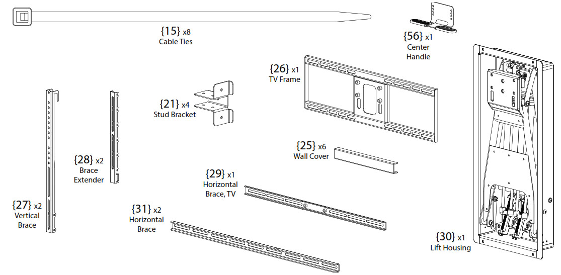
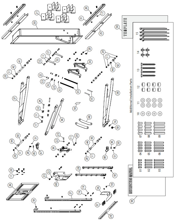
Before you begin, please verify that all components are included and undamaged. If any parts are missing or damaged, contact MantelMount. Never proceed with missing or damaged parts! Layout all components and make sure you identify that each one has a match in the diagram. Some of the parts included will not be used during installation. Do not proceed if you do not understand and identify all of the components.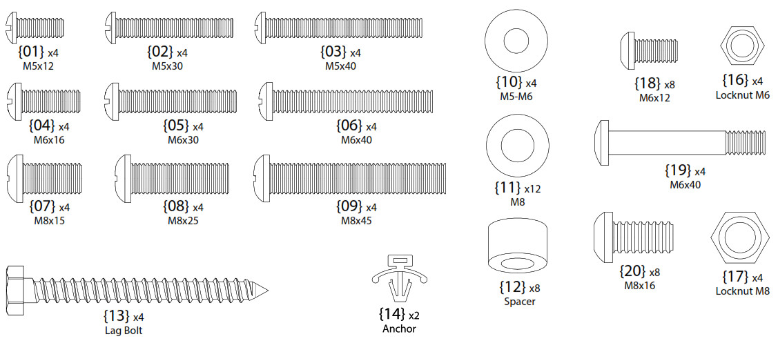
Please verify that your installation meets all of these CRITICAL requirements:
AMantelMount is designed for use only with decorative fireplaces that are not the primary heat source for a house. Temperature at the front edge of mantle should never exceed 110° F.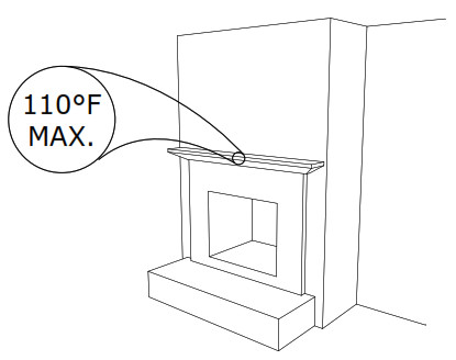 BWall must be WOOD STUD FRAME only. There must be at least 2 studs available for mounting. Wall covering must not exceed 5/8 inch thick.For other types of walls or other types of installations please visit the FAQ section at www.MantelMount.com.
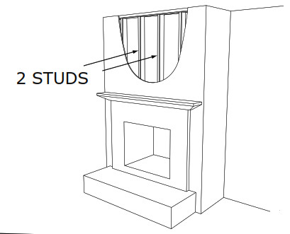 CMantle must not extend from mounting surface more than 19 inches (22 inches for non-recessed installations). MantelMount can not extend past a mantel larger than 19 inches. Larger mantels will also reduce the amount of side-to-side swivel.
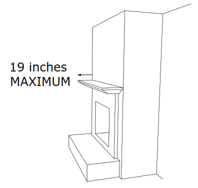 DTELEVISION REQUIREMENTS:
- Weight must be below 110 pounds (56 Kg).
- Screen size larger than 50 diagonal inches.
- Mounting screw holes are VESA compliant. For non-VESA hole patterns, please visit the FAQ section at www.MantelMount.com.

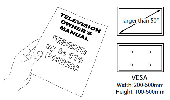
ENote: This is not an installation step, only a verification. Do not use these dimensions during installation.The space above the mantle must be taller than the TV. The required space depends on how far out the mantle extends. Refer to chart below and add this additional height to the TV height to determine if space is tall enough.
| If mantle extends: | This is required space height: |
| Less than 10 inches | TV height plus 6 inches |
| 10 – 14 inches | TV height plus 8 inches |
| 14 – 16 inches | TV height plus 10 inches |
| 16 – 19 inches | TV height plus 15 inches |
![]() Use a Vertical Brace {27} to determine if your television is a flat back or an irregular back. An irregular back will require spacers and longer screws to fill any spaces between the Vertical Brace and the TV. The Braces must be parallel to your television screen.
Use a Vertical Brace {27} to determine if your television is a flat back or an irregular back. An irregular back will require spacers and longer screws to fill any spaces between the Vertical Brace and the TV. The Braces must be parallel to your television screen.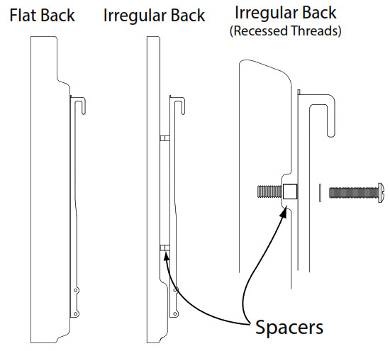
![]() Choose the correct screw diameter and length for the TV. Hand-thread screw combination into the TV to ensure there is adequate thread engagement without hitting the bottom of threaded insert. Use only minimum amount of spacers (if required).
Choose the correct screw diameter and length for the TV. Hand-thread screw combination into the TV to ensure there is adequate thread engagement without hitting the bottom of threaded insert. Use only minimum amount of spacers (if required).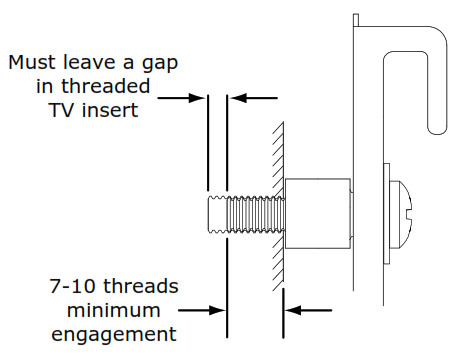
![]() CAUTION:Do Not use screws that are too long for the threaded inserts of Television. This can damage internal components.
CAUTION:Do Not use screws that are too long for the threaded inserts of Television. This can damage internal components.
![]() Possible Screw Combinations shown with maximum spacer usage (if spacers are required).
Possible Screw Combinations shown with maximum spacer usage (if spacers are required).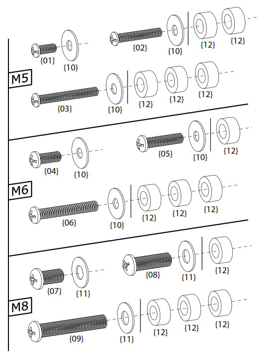
![]() IMPORTANT INFORMATION: The Vertical Braces {27} are a fixed distance higher than the bottom of the Lift Housing Frame {30}. This relationship can be used to calculate most mounting situations such as centering the TV in an alcove or mounting the TV at a specific height on the wall.If you measure the distance from the bottom of your TV (or Sound Bar) to the bottom of the Vertical Braces {27} (see: page 5) you will automatically know the distance from the bottom of your TV to the bottom of the Lift Housing {30}.You can use this information to install the Lift Housing on the wall in order to locate your TV to any specific height you desire.Example: If the Vertical Braces are attached 10 inches from the bottom of the TV, then the bottom of the cutout opening should be 4 inches higher than where you want the bottom edge of the TV on the wall (10″ – 6″ = 4″).If you are installing above a mantel, then your installation must still have the additional clearance for downward motion stated in the chart in Step 9.
IMPORTANT INFORMATION: The Vertical Braces {27} are a fixed distance higher than the bottom of the Lift Housing Frame {30}. This relationship can be used to calculate most mounting situations such as centering the TV in an alcove or mounting the TV at a specific height on the wall.If you measure the distance from the bottom of your TV (or Sound Bar) to the bottom of the Vertical Braces {27} (see: page 5) you will automatically know the distance from the bottom of your TV to the bottom of the Lift Housing {30}.You can use this information to install the Lift Housing on the wall in order to locate your TV to any specific height you desire.Example: If the Vertical Braces are attached 10 inches from the bottom of the TV, then the bottom of the cutout opening should be 4 inches higher than where you want the bottom edge of the TV on the wall (10″ – 6″ = 4″).If you are installing above a mantel, then your installation must still have the additional clearance for downward motion stated in the chart in Step 9.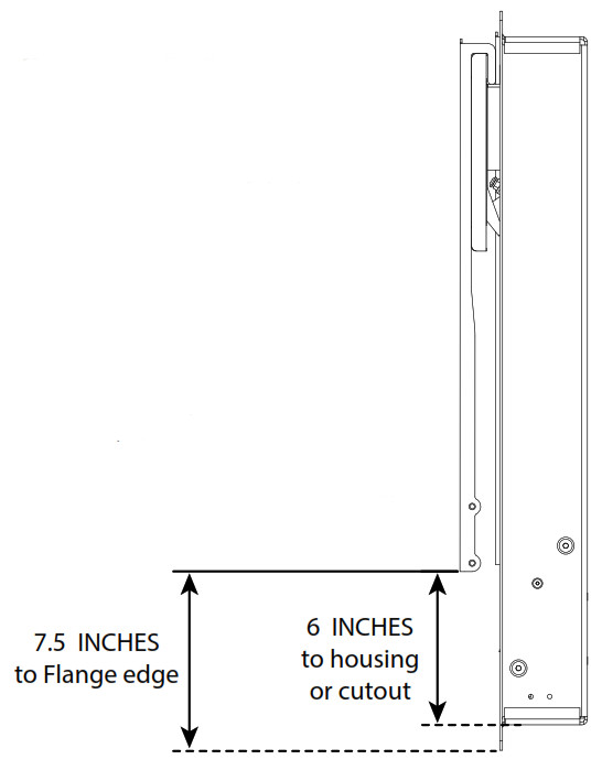
![]() The Vertical Braces {27} are always mounted higher than the bottom of the TV. However, the Brace Extenders {28} will be mounted one of two ways:Without a Sound Bar – The Brace Extenders are installed within a few inches above the bottom of the TV.With a Sound Bar – The Brace Extenders are installed below the TV with enough room to install the Sound Bar onto the Horizontal Brace {29}.
The Vertical Braces {27} are always mounted higher than the bottom of the TV. However, the Brace Extenders {28} will be mounted one of two ways:Without a Sound Bar – The Brace Extenders are installed within a few inches above the bottom of the TV.With a Sound Bar – The Brace Extenders are installed below the TV with enough room to install the Sound Bar onto the Horizontal Brace {29}.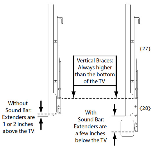
![]() Attach the Vertical Braces {27} to the TV so the bottoms of the Vertical Braces are at least seven inches higher than the bottom of the TV.If the holes on the TV are lower than the braces, install the lower screws through the Brace Extenders {28} using the included Spacers {12}.
Attach the Vertical Braces {27} to the TV so the bottoms of the Vertical Braces are at least seven inches higher than the bottom of the TV.If the holes on the TV are lower than the braces, install the lower screws through the Brace Extenders {28} using the included Spacers {12}.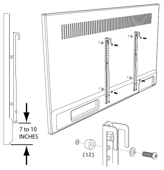
![]() Attach the TV Horizontal Brace {29} to the Extenders {28}. Use the Vertical Braces to align the Extenders.Attach the Extenders to the Vertical Braces {27}.Attach the Center Handle {56}, making sure the Handle is within one inch from the bottom of the TV.
Attach the TV Horizontal Brace {29} to the Extenders {28}. Use the Vertical Braces to align the Extenders.Attach the Extenders to the Vertical Braces {27}.Attach the Center Handle {56}, making sure the Handle is within one inch from the bottom of the TV.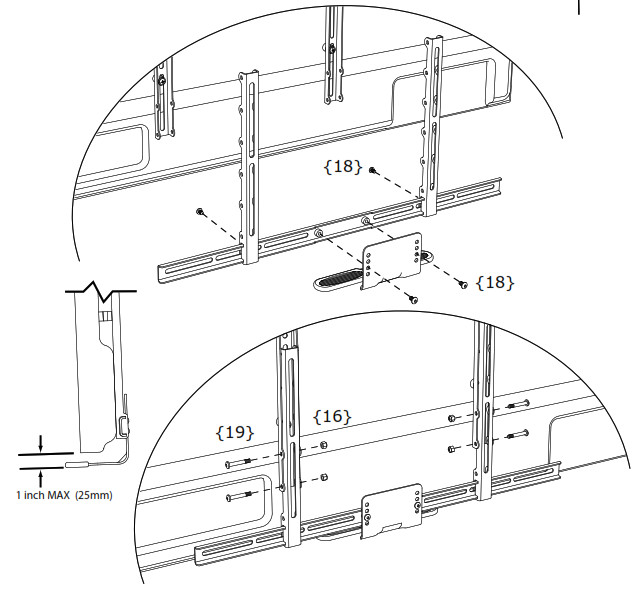
![]() Measure the distance from the bottom of the Vertical Braces {27} (not the Extenders) to the bottom of television or Sound Bar (not the Center Handle).Write down this distance to use in Step 9.
Measure the distance from the bottom of the Vertical Braces {27} (not the Extenders) to the bottom of television or Sound Bar (not the Center Handle).Write down this distance to use in Step 9.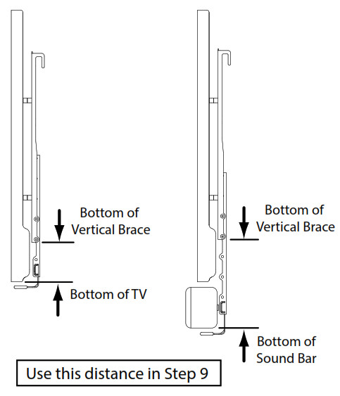
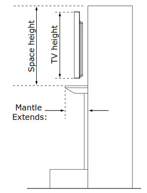
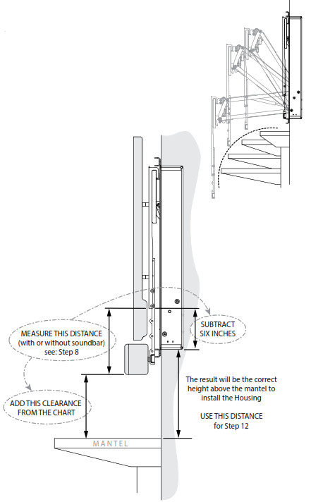
![]() Determine the Vertical Position of the Housing:This image at right shows that the further out a mantle extends, the more it will interfere with the arc of the lowering TV. The chart below gives clearance heights from the bottom of the TV to the top of various mantel sizes.However, the MM750 Lift Housing {30} is often located even higher on the wall than the TV. To locate the TV so it has enough clearance and doesn’t hit the mantel, you will need to know how much higher the Housing is than the bottom of the TV. Then you can locate the Housing on the wall.NOTE: If there is extra space available, due to a high ceiling for example, then these heights are only minimum requirements.
Determine the Vertical Position of the Housing:This image at right shows that the further out a mantle extends, the more it will interfere with the arc of the lowering TV. The chart below gives clearance heights from the bottom of the TV to the top of various mantel sizes.However, the MM750 Lift Housing {30} is often located even higher on the wall than the TV. To locate the TV so it has enough clearance and doesn’t hit the mantel, you will need to know how much higher the Housing is than the bottom of the TV. Then you can locate the Housing on the wall.NOTE: If there is extra space available, due to a high ceiling for example, then these heights are only minimum requirements.
| If mantle extends: | Required Clearance: |
| Less than 10 inches | Add 5 inches |
| 10 – 14 inches | Add 7 inches |
| 14 – 16 inches | Add 9 inches |
| 16 – 19 inches | Add 14 inches |
Installation Options: Surface Mount
SURFACE MOUNT (non-recessed) installation using Horizontal Braces {31} to attach to existing wall studs, on top of existing drywall.The Horizontal Braces can reach studs that are up to 34 inches (875mm) apart. They attach flush to the back of the Lift Housing {30}.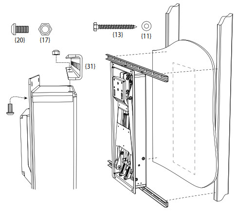 SURFACE MOUNT (non-recessed) installation onto stone or concrete walls using the six holes in the back of the Lift Housing {30}.The wall must be solid stone or concrete that can hold five times the weight of all combined equipment. This surface must not be a facade or non-structural material. Use concrete anchors (not included) to attach the Lift Housing to the surface.
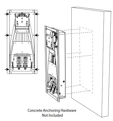
Installation Options: Recessed using Horizontal Braces {31}
RECESSED installation using the Horizontal Braces {31} to attach to existing wall studs: The Horizontal Braces attach to the flange on the front of the Lift Housing {30}. The Braces can be located off-center to the Housing, if needed, to reach the nearest stud. Use the included Template to mark the location to cut the drywall. This installation is easiest when there is no center stud that needs to be cut to make room. Paintable Wall Covers {25} can be snapped onto the Horizontal Braces.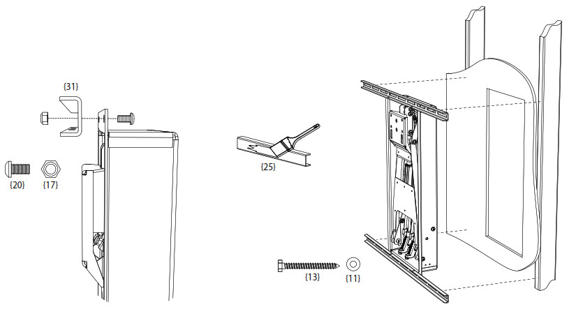
Installation Options: Recessed using 2×4 Stud Brackets {21}
MM750 includes brackets that make it easier to install horizontal pieces of 2×4 bracing inside the wall. This is because all of the attachment holes in the Brackets can be reached for drilling and screwing simply by reaching through the opening that is cut for the Lift Housing {30}, see FIG. A.
When wall studs are far apart, or when a center stud needs to be cut, or when the cleanest look is desired, sections of horizontal 2×4 can be installed through the cutout. They provide a solid structure for the mount without the need for the Horizontal Braces {31}. The mount is attached with Lag Bolts through the holes in the front flange of the Lift Housing {30}.
The Stud Brackets can be attached with lag bolts, or bolts with nuts and washers. The hardware to attach the Stud Brackets is not included.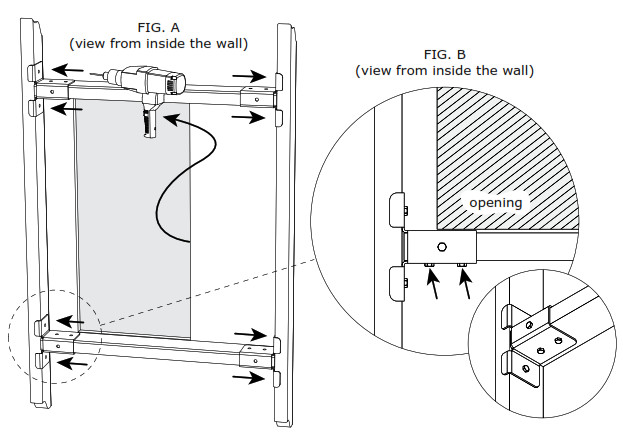
Cutting a Center Stud:
When cutting a center stud, measure 1.5″ above and below the template mark before the opening is cut out. The drywall will hold the stud in place while it is cut. Plunge cut through the stud at both locations and attach the cut ends to the cross bracing when they are installed, see FIG. C.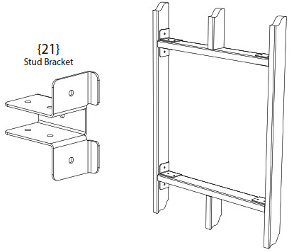
 Note: If the Bracket is near the cutout opening, make sure to orient the attaching hardware away from the opening so they do not interfere with the Lift Housing {30}. This hardware is attached before the braces are installed into the wall, see FIG. B.
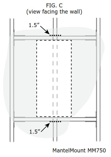
![]() Marking the Location for the Lift Housing {30}Use the Template to mark the location of the Housing according to the height from step 9. Make sure the Template is level and centered. Mantel Mount is located in the same spot for all installations.If you are surface mounting, you will only need to mark the corners, but for recess mounting you will trace the entire template to cut out the drywall.
Marking the Location for the Lift Housing {30}Use the Template to mark the location of the Housing according to the height from step 9. Make sure the Template is level and centered. Mantel Mount is located in the same spot for all installations.If you are surface mounting, you will only need to mark the corners, but for recess mounting you will trace the entire template to cut out the drywall.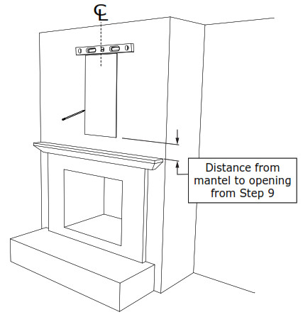
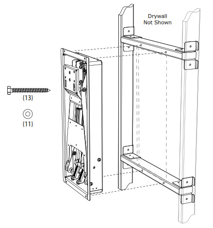
![]() Install the Lift Housing {30}Locate, Mark, and Pre-Drill Studs in the Wall. All holes must be pre-drilled with 7/32″ drill bit to a depth of 2.5 inches (65mm) including wall covering. Note: Wall covering (drywall) must not exceed 5/8″ thickness.Install the Lift Housing to the wall using one of the options previously described.
Install the Lift Housing {30}Locate, Mark, and Pre-Drill Studs in the Wall. All holes must be pre-drilled with 7/32″ drill bit to a depth of 2.5 inches (65mm) including wall covering. Note: Wall covering (drywall) must not exceed 5/8″ thickness.Install the Lift Housing to the wall using one of the options previously described.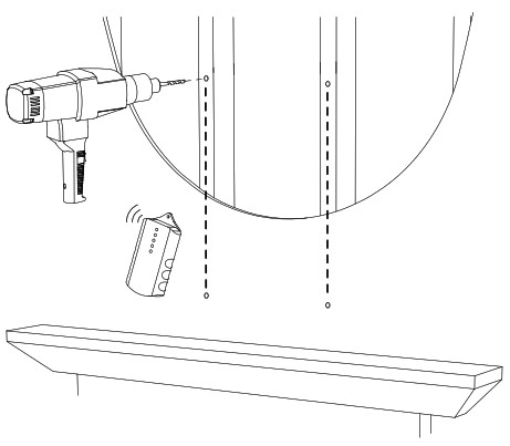
![]() CAUTION:Do Not overtighten Lag Bolts {13}. Tighten only until the washers are firmly against the Housing. Damage due to overtightening can cause property damage or injury.
CAUTION:Do Not overtighten Lag Bolts {13}. Tighten only until the washers are firmly against the Housing. Damage due to overtightening can cause property damage or injury.
![]()
![]() THIS STEP REQUIRES TWO PEOPLEPull the Safety Braces out to the ready position as shown. You might need to flex them over the screws. Do not bend the Safety Braces.Firmly and slowly pull down the Arm until the Lifting Mechanism is in a horizontal position. The second person must swing the Safety Braces upward until they grab the crossmember of the Upper Arm.The Lifting Mechanism should stay at a horizontal position.
THIS STEP REQUIRES TWO PEOPLEPull the Safety Braces out to the ready position as shown. You might need to flex them over the screws. Do not bend the Safety Braces.Firmly and slowly pull down the Arm until the Lifting Mechanism is in a horizontal position. The second person must swing the Safety Braces upward until they grab the crossmember of the Upper Arm.The Lifting Mechanism should stay at a horizontal position.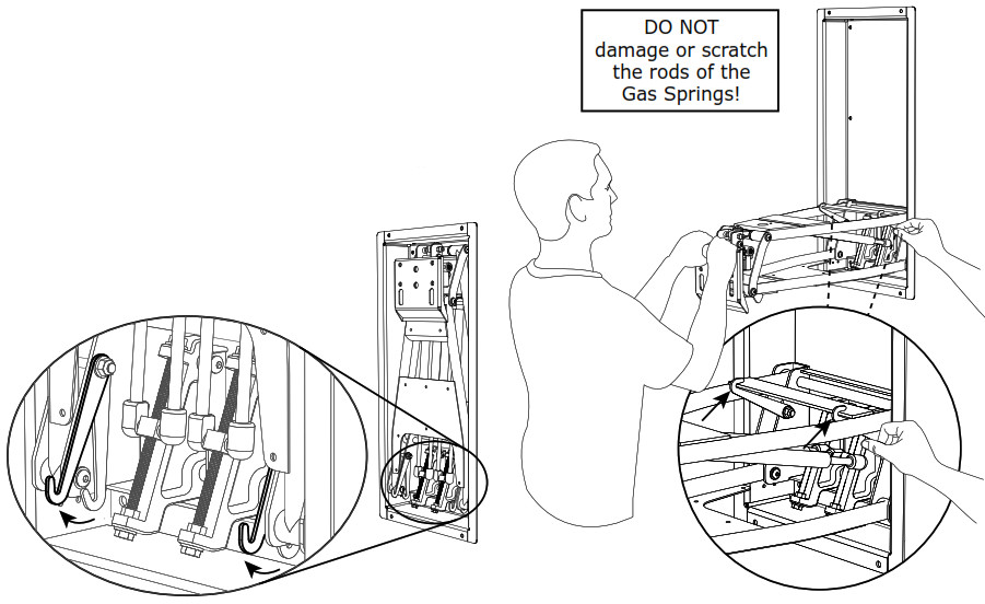
![]()
![]() WARNING:DO NOT put hands into Lifting Mechanism while operating the mount. Severe Injury can occur due to pinching or crushing. Always use the Safety Braces when working near or inside MantelMount.
WARNING:DO NOT put hands into Lifting Mechanism while operating the mount. Severe Injury can occur due to pinching or crushing. Always use the Safety Braces when working near or inside MantelMount.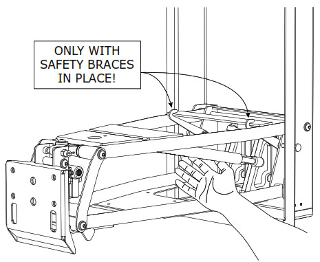
![]() Install the TV Frame {26} using 4 Screws {20} and Washers {11}. These screws can also be used to fine tune level the TV. Always remember to tighten.
Install the TV Frame {26} using 4 Screws {20} and Washers {11}. These screws can also be used to fine tune level the TV. Always remember to tighten.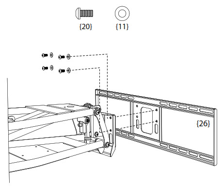
![]()
![]() THIS STEP REQUIRES TWO PEOPLECarefully hang the Television onto the TV Frame making sure that both hooks on the Vertical Braces {27} engage the TV Frame.DO NOT allow the Television to drop far enough to cause the Lifting Mechanism to hit the mantle.MantelMount comes pre-adjusted to reduce the possibility of contacting the mantle, but you should always be prepared to remove the television at this stage to make the proper correction.If the Lift Housing {30} appears to be too close to the mantle, remove television. Go to STEP 17 and make an adjustment to the Bottom Stop position. Repeat this process until the Lifting Mechanism is a safe distance from the mantle when the TV is installed.Some older TVs are not weight balanced. If the TV is much heavier on one side, slide the TV slightly sideways to balance and level the TV.Attach with 4 Screws {18}.
THIS STEP REQUIRES TWO PEOPLECarefully hang the Television onto the TV Frame making sure that both hooks on the Vertical Braces {27} engage the TV Frame.DO NOT allow the Television to drop far enough to cause the Lifting Mechanism to hit the mantle.MantelMount comes pre-adjusted to reduce the possibility of contacting the mantle, but you should always be prepared to remove the television at this stage to make the proper correction.If the Lift Housing {30} appears to be too close to the mantle, remove television. Go to STEP 17 and make an adjustment to the Bottom Stop position. Repeat this process until the Lifting Mechanism is a safe distance from the mantle when the TV is installed.Some older TVs are not weight balanced. If the TV is much heavier on one side, slide the TV slightly sideways to balance and level the TV.Attach with 4 Screws {18}.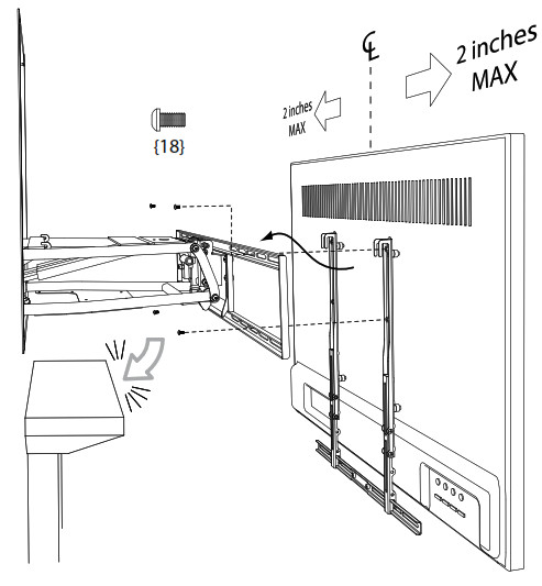
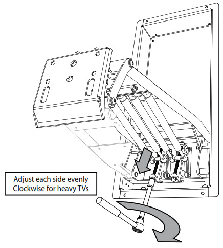
![]() Adjusting for Television weight: With Safety Braces in place, use a socket wrench with an extension to adjust the long bolts inside the Lift Housing {30}. Take turns adjusting each side so they stay relatively even with each other.Turn the bolts clockwise (AS SHOWN BELOW) to pull the Gas Springs down and increase the lifting force for heavy TVs, or turn counter-clockwise for lighter TVs. This adjustment can take several turns. Reference the sticker scale on each side for the weight of the TV. Each scale represents the TOTAL WEIGHT of the TV.Adjust the bolt until the TV gently stays in the lowered position. When the mount moves with a neutral feel within the Safety Braces, un-latch the Safety Braces and check the mount operation throughout the full range of motion.(TV and some components are not shown in these images for clarity.)
Adjusting for Television weight: With Safety Braces in place, use a socket wrench with an extension to adjust the long bolts inside the Lift Housing {30}. Take turns adjusting each side so they stay relatively even with each other.Turn the bolts clockwise (AS SHOWN BELOW) to pull the Gas Springs down and increase the lifting force for heavy TVs, or turn counter-clockwise for lighter TVs. This adjustment can take several turns. Reference the sticker scale on each side for the weight of the TV. Each scale represents the TOTAL WEIGHT of the TV.Adjust the bolt until the TV gently stays in the lowered position. When the mount moves with a neutral feel within the Safety Braces, un-latch the Safety Braces and check the mount operation throughout the full range of motion.(TV and some components are not shown in these images for clarity.)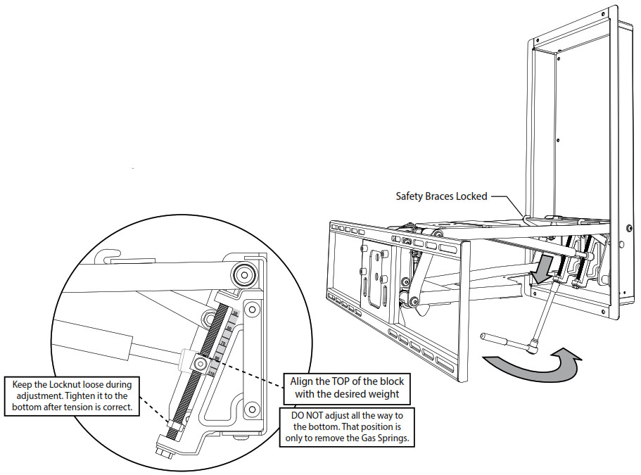
 Verify the proper lifting performance: MantelMount lifting force is designed to keep the TV securely in the up position while also allowing the TV to gently rest in the down position. See the diagram below for the correct lifting adjustment.
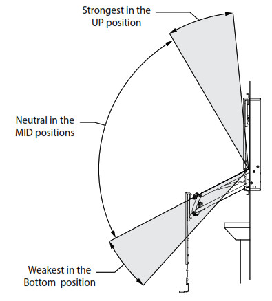
Adjusting the Hard Stops for Range of Motion:
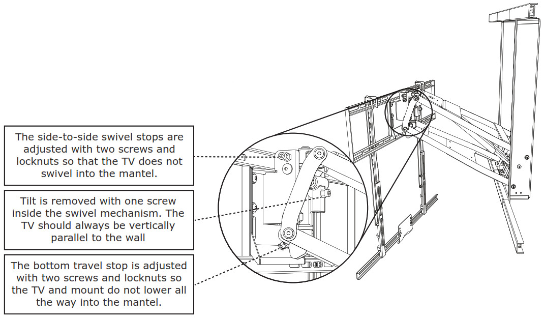
![]() Adjusting the Bottom Stop Position: Loosen the Locknuts and adjust the Bottom Stop screws to the desired stopping position.There are two screws underneath the Lifting Mechanism. Turn these screws inward until they tighten at the desired lower position.Tighten both locknuts after the adjustments are made.
Adjusting the Bottom Stop Position: Loosen the Locknuts and adjust the Bottom Stop screws to the desired stopping position.There are two screws underneath the Lifting Mechanism. Turn these screws inward until they tighten at the desired lower position.Tighten both locknuts after the adjustments are made.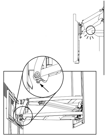
![]() Adjusting the Side Swivel Stop Positions:Loosen the Locknuts and adjust the Swivel Stop screws to the desired stopping positions, both left and right.Tighten both locknuts after the adjustments are made.
Adjusting the Side Swivel Stop Positions:Loosen the Locknuts and adjust the Swivel Stop screws to the desired stopping positions, both left and right.Tighten both locknuts after the adjustments are made.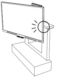 Note: If no swivel is desired, it may be necessary to remove the locknuts and re-attach them on the other side of the Swivel Bracket so that the Screws can be threaded out to their maximum length.
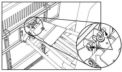
![]() Removing unwanted Tilt:The TV should be fairly vertical in the up position and parallel to the wall. If the TV is tilted slightly downward, back out the adjustment screw slightly as shown. Tighten the locknut after the adjustment is made.
Removing unwanted Tilt:The TV should be fairly vertical in the up position and parallel to the wall. If the TV is tilted slightly downward, back out the adjustment screw slightly as shown. Tighten the locknut after the adjustment is made.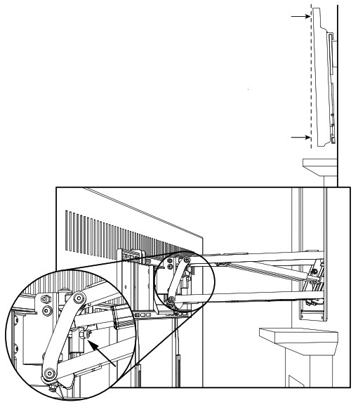
![]() Attaching Cables:If cables are attached using the Anchors {14}, ensure that cables are not near the pinching area of the TV Frame and swivel portion of the mount. If cables are near the swivel, loop them away from the pinch area securely.
Attaching Cables:If cables are attached using the Anchors {14}, ensure that cables are not near the pinching area of the TV Frame and swivel portion of the mount. If cables are near the swivel, loop them away from the pinch area securely.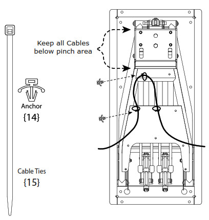
![]() Reference Only: This is one possible configuration for the signal cables. Each segment of the cables has extra length so that the cables are not stressed or kinked when the mount is moved. Ensure that cables do not get pinched between brackets when the mount is raised.
Reference Only: This is one possible configuration for the signal cables. Each segment of the cables has extra length so that the cables are not stressed or kinked when the mount is moved. Ensure that cables do not get pinched between brackets when the mount is raised.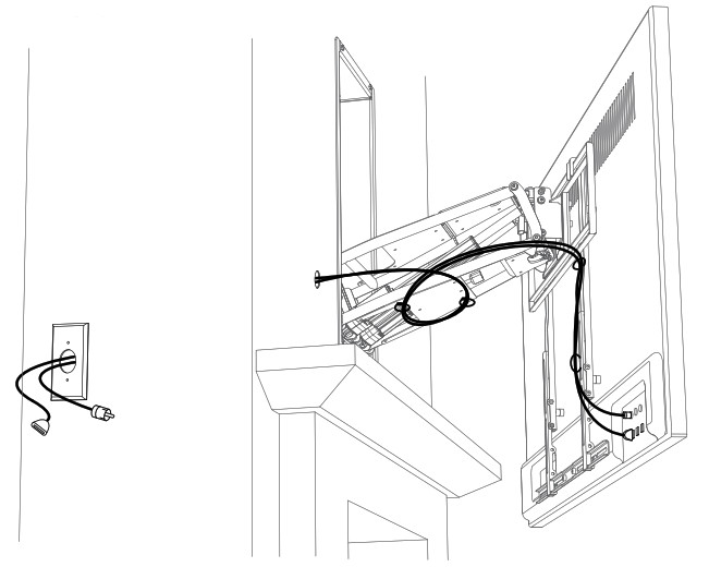
![]() CAUTION:Never release the handle before it is fully upright. MantelMount is strongest in the top position, and allowing it to slam closed can damage televisions. Always control the lifting process.
CAUTION:Never release the handle before it is fully upright. MantelMount is strongest in the top position, and allowing it to slam closed can damage televisions. Always control the lifting process.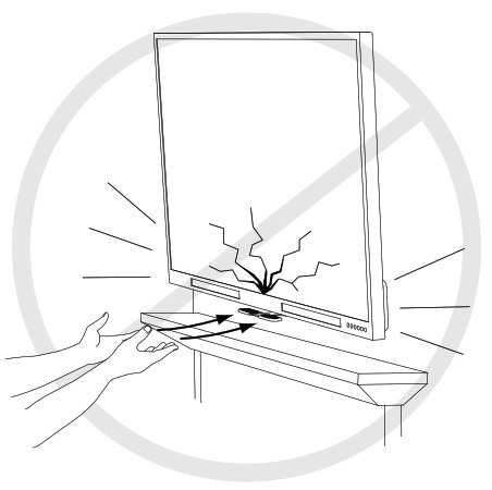
![]() CAUTION:Never allow small children to play around or operate MantelMount. Property damage or personal injury can occur.
CAUTION:Never allow small children to play around or operate MantelMount. Property damage or personal injury can occur.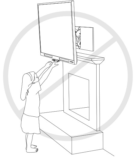
| ITEM NO. | PAM NUMBER | DESCRPTION | QTY. |
| I | 12189 | M5x12 | 4 |
| 2 | 12193 | M5 x 30 | 4 |
| 3 | 12191 | MS x 40 | 4 |
| 4 | 12193 | M6 x16 | 4 |
| 5 | 12194 | 446×30 | 4 |
| 6 | 12195 | 1.46 x40 | 4 |
| 7 | 12197 | 448×15 | 4 |
| 8 | 121% | M8 x 25 | 4 |
| 9 | 12199 | M8 x45 | 4 |
| 10 | 12166 | Washer M6 | 4 |
| II | 14126 | Washer M8 x 2 | |
| 12 | 12122 | Spacer | 8 |
| 13 | 14137 | Log Bolt Max 63 | 4 |
| 14 | 14110 | Cable Toe Amin( | 4 |
| 1S | 12162 | Cable Tie | 8 |
| 16 | 12183 | Locknut M6 | 6 |
| 17 | 12187 | Locknut MB | 8 |
| 18 | 12178 | Round Saes M6 x 12 | 8 |
| 19 | 12255 | Ibund Saew 446×40 | 4 |
| 20 | 12176 | Fbund Saew Max 16 | 34 |
| 21 | 15023 | Stud Becket | 4 |
| 22 | 12186 | Nut M8 | 7 |
| 23 | 21088 | SocketCap Saew M8 x 25 | 3 |
| 24 | 210% | SocketCap Same 143 x40 | 2 |
| 25 | 21143 | Wag Cover | 6 |
| 26 | 21050 | 1V Frame Welded | 1 |
| 27 | 14338 | Vertical BM! | 2 |
| 28 | 14356 | &ace Extender | 2 |
| 29 | 14060 | 1N1 Horizontal Braze | 1 |
| 30 | 21115 | (recess Frame, 750,Welded | 1 |
| 31 | 21039 | Horizontal Berge | 2 |
| 32 | 14115 | %ling Sixng Mount | 4 |
| 33 | 12247 | Disk SpringWasher 1•13 | 4 |
| 34 | 21085 | Adjustment Block | 2 |
| 35 | 21180 | Hex Bolt M8 x 160 | 2 |
| 36 | 12160 | Gas Spring | 4 |
| 37 | 21110 | Upper Arm, 750 Welded | 1 |
| 38 | 21081 | Laver Arm Welded | 1 |
| 39 | 21060 | Suave! | 1 |
| 40 | 21045 | Tit Brecket,Wekkd | 1 |
| 41 | 21044 | Mle,750 | 1 |
| 42 | 21119 | Busing | 4 |
| 43 | 21037 | Me | 2 |
| 44 | 21121 | Bushing | 4 |
| 45 | 21092 | Washer M8 x 3 x 24 | 2 |
| 46 | 21035 | Me | 2 |
| 47 | 21054 | bp Prvot | 1 |
| 48 | 21041 | Connector Brea | 1 |
| 49 | 21063 | Bottom Pivot | 1 |
| 50 | 21178 | [bond Screw 1A6 x 15 | 2 |
| 51 | 21163 | Set SaewM5x IS | 2 |
| 52 | 21144 | Round Screw M8 x60 | 1 |
| 53 | 21135 | Safety WC! | 1 |
| 54 | 21211 | Warning Stsdier | 1 |
| 55 | 21206 | adjustment Sticker | 2 |
| 56 | 14062 | Center Mende | 1 |
| 57 | 12222 | Handle Rubbeaemix Change | 2 |
| 58 | 21190 | Cardboard Template 735x 335rnm | 1 |
| 59 | MM750M | Instruction Manual | I |
Customer Service:(800)-897-9755www.MantelMount.com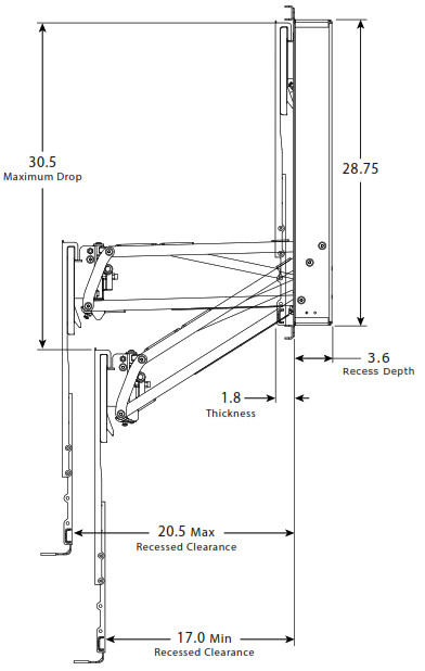
Exclusive MantelMount Features!Auto-Straightening: Flattens the TV as it is raised to the upper position to prevent rotation into the wall
Safety Braces: Hold the mount safely in the down position to work behind the TV during installation
Smooth Operation: Solid shafts with polymer bushings at each pivot point provide silent movementTemperature-Sensing Handles: Change to red color at temperatures above 110ºF to warn users if the freplace is too hot for TV safety
Full Manufacturer Warranty:
MantelMount will replace or repair any product or part that proves defective due to improper workmanship or material during the warranty period. Visit www.MantelMount.com for details.This Installation Manual is available for download as a PDF document at www.MantelMount.com. The PDF version can be used to see larger images or to zoom in for much greater detail.
U.S. Pat. No. 8,864,092 01Jan2018 MantleMount MM750
References
[xyz-ips snippet=”download-snippet”]