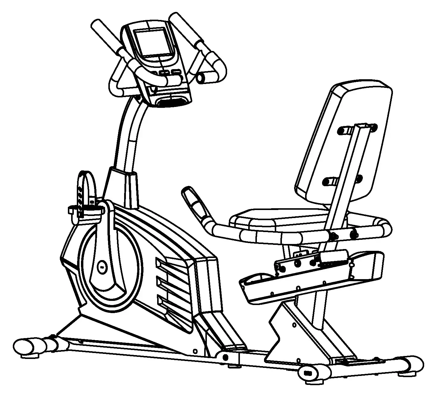
REGENERATINGMAGNETIC RECUMBENT BIKEME-706
IMPORTANT: Please read the Important Safety Notice and Assembly Information in the Owner’s manual before assembling this product.Assembly Manual190429
| Part No. | Description | Q’ty |
| 1 | Mainframe | 1 |
| 7 | Rear support tube | 1 |
| 32 | Seat support bracket | 1 |
| 4 | Front post | 1 |
| 34 | Back cushion | 1 |
| 2 | Front stabilizer | 1 |
| 3 | Rear stabilizer | 1 |
| 8 | Front post cover | 1 |
| 19L/R | Pedal (L&R) | 1 |
| 97L/R | Rear support tube Cover (L&R) | 1 |
| 51/R | Handlebar L & R | 1 |
| 37 | Rear handlebar | 1 |
| 33 | Seat cushion | 1 |
| 23L/R | Left /Right cover for the sliding tube | 1 |
| 6 | Computer | 1 |
STEP 1Attach Front Stabilizer (#2) with Allen Bolt (#21), Locking washer (#98), and Curved washer (#15) to the Main Frame (#1).
STEP 2Attach the Rear Stabilizer (#3) with Allen Bolt (#21), Curved washer (#15), and Locking washer (#98) to the Rear Support tube (#7).
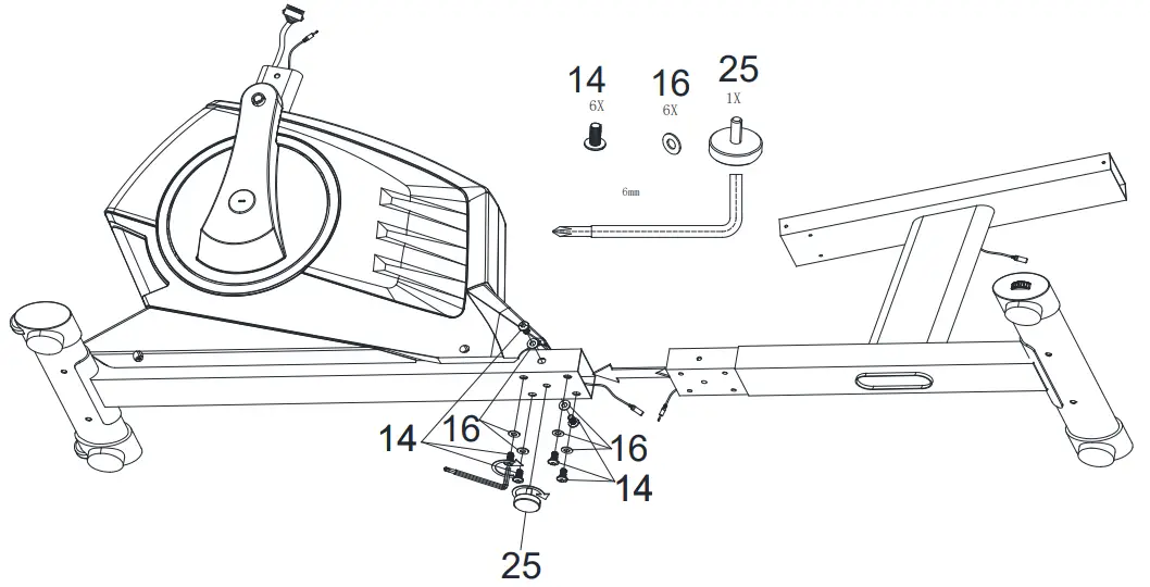
STEP3
- Connect Main Frame (#1) and Rear Support tube (#7) with Allen Bolt (#14) and Flat washer (#16).
- Attach the Level Adjustment (#25).
STEP 4
- Slide Front post cover (#8) onto the Front post (#4).
- Connect Middle computer wire (#9), Front extension hand pulse wire (#10) to Middle extension hand pulse wire (#17), and Lower computer wire (#18).
- Attach the Front Post (#4) to the mainframe with Allen Bolt (#14), Curved washer (#15), and Flat washer (#16).
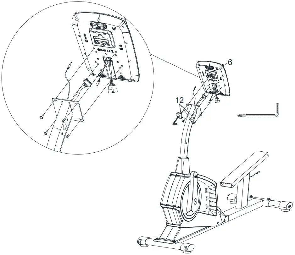
STEP 5Connect the computer sensor wire and the computer wire to the Front post connectors, and attach the computer (#6) to the Front Post with the pre-assembled Screws (#12).
STEP 6Secure the Handlebar (#5L, #5R) to the Front Post with Allen Bolts (#14).
STEP 7
- Slightly lift the Seat bracket (#94) as it slides into the Rear support tube (#7).
- Thread in the Ball end cap (#35) into the Quick release handle (#29).
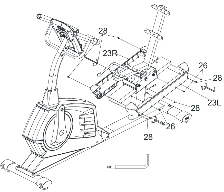
STEP 8Attach the Cover for the Sliding tube (#23L, #23R) with Self-tapping screws (#26) and Screws (#28).
STEP 9
- Secure the Rear Handlebar (#37) to the Seat bracket (#94) with a Curved washer (#15), Carriage bolt (#43), and Acorn nut (#44).
- Connect Hand pulse wire (#42) and Rear extension hand pulse wire (#22).
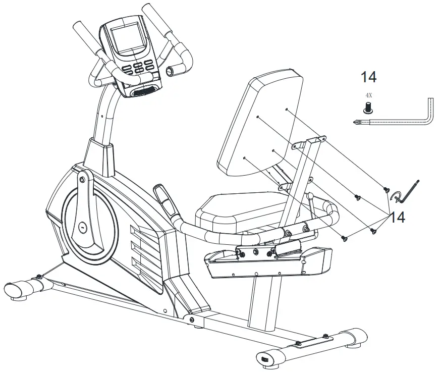
STEP 10Attach the Seat cushion (#33) to the Seat bracket (#94) with Allen Bolts (#14).
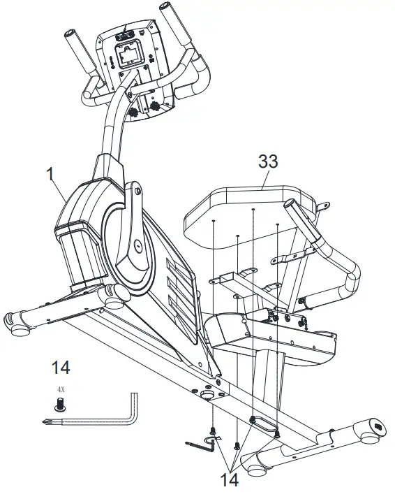
STEP 11Attach Back Cushion (#34) to the Seat bracket (#94) with Allen bolts (#14).
STEP 12Attach the Rear support tube cover (#97L, #97R) with Self-Tapping screw STx5 ½ (#26) and Self-Tapping Screw ST5x ¾ (#55).
STEP 13Thread the Left Pedal (#19L) and Right Pedal (#19R) into the crank.
 report this ad
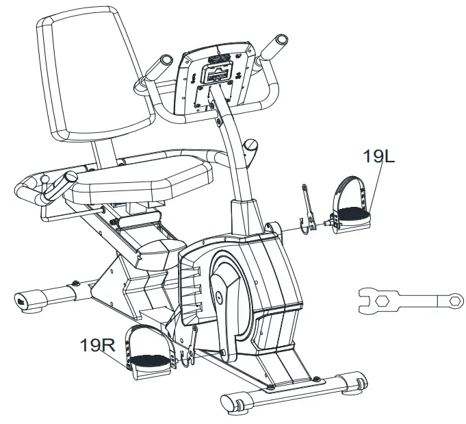
IMPEX® INC.2801 S. Towne Ave, Pomona, CA 91766Tel: (800) 999-8899 Fax: (626) 961-9966www.marcypro.com[email protected]
References
[xyz-ips snippet=”download-snippet”]