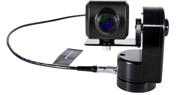
Marshall CV-PT-HEAD Micro Pan/Tilt Head
Introduction
The CV-PT-HEAD can be controlled by CV-MICRO-JYSTK or any BR Remote style controller. These controllers generate RS485 data which can be connected directly to the CV-PT-HEAD or sent via an IP network with IP adaptors. The RS485 data can be sent up to 3,000+ feet (1km) on a four (4) pin XLR cable. Power for the CV-PT-HEAD can be up to 35V so cable length can be extended very long rangesby increasing the voltage to the CV-MICRO-JYSTK remote end. Inside the unit is a 12v regulated supply for the camera so it does not matter what voltage you send to the CV-MICRO-JYSTK, the camera will always be provided 12V power. Marshall cameras use (VISCA) commands to adjust settings in the camera. The control protocols for these cameras are embedded in the CV-PT-HEAD and can be connected to the camera with included patch cable. The camera itself can then be controlled via BR Remote controllers. The Camera CCU output is RS422 and is on the 7pin connector passed through to camera with patch cable.
The CV-PT-HEAD is IP65 weatherproof and can be used outside. This makes a perfect match for the Marshall CV503-WP IP67 weatherproof camera model for outdoor or dirty environment use. There are slipping clutches on both pan and tilt motors which prevent damage to the mechanics if it is moved inadvertently during rigging or if it hits an obstruction during movement. Need to hang it upside down – no problem. There are 3x M4 mounting threads as well as a ¼”-20 on the base of the PT Head. Simply flip the image in the Marshall Camera OSD Menu.
Joystick ControlThe CV-PT-HEAD contains 10 gears. Some controllers can select any gear, but others can only select a fewer number of gears. The movement is fully proportional to the joystick displacement in all gears. If the ‘turbo’ button is enabled on the controller this will set the speed to the fastest gear triggered by holding down the button.
Pre-set PositionsThe CV-PT-HEAD has the capacity to store up to 64 pre-set positions although some controllers can only access 4 positions. When first powering the unit on you will need to manually set a ‘Home’ position or storing the positions you need. You can set a ‘Home’ position by using a known picture position from the camera or by driving it to the ends of the pan and tilt travel. Doing this will enable it to re-call previously stored positions.
Connections
The CV-PT-HEAD is supplied with a short cable to connect it to a controller. This cable can be simply extended following the wiring diagram below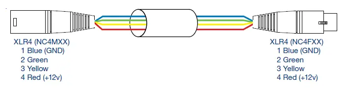
4 Pin input plug – FGG.0B.304.CLAD52ZPin 1 = GND (Blue)Pin 2 = RS485 data A (Green)Pin 3 = RS485 data B (Yellow)Pin 4 = Power 12 – 35v (Red)
7 Pin plug for camera power & data – FGG.0B.307.CLAD52ZPin 1 = GND (Blue)Pin 2 = RS422/485 data A TO camera (Green) Also semi-duplex return data.Pin 3 = RS422/485 data B TO camera (Yellow) also semi-duplex return data.Pin 4 = Power 12v camera power (Red)Pin 5 = future usePin 6 = future usePin 7 = future use
When power is connected the blue LED on the side will flash 3 times whilst the CV-PT-HEAD is booting up. After this sequence, the LED will indicate 3 states.
Permanently ON = Power applied; data received but not being addressed.Very Fast Flashing = Being addressed and should respond to commands.Flashing Very Slowly = Power but no data.
Cable Management
On the pan cover, under the camera plate are two M2.5 threaded holes. These can be used to attach cable management clips if required.
Pan & Tilt Clutch Adjustment
Both the pan and the tilt clutches can be adjusted if needed. To adjust the pan clutch, remove the Pan Cover which is secured with a single screw. The cover will need to be prized off as it is sealed with siliconesealant. The Adjustment nut is on the top of the shaft and locked with an M3 grub screw. Use a 1.5mm Allen wrench key to loosen the locking screw and tighten the clutch adjustment nut until to achieve the required clutch movement. It should be set as lightly as possible without slipping. If it is adjusted too tightly, damage may occur to the pan motor gearbox. Clean all the sealant from the cover and the body and re-apply a very thin layer of silicone sealant before re-fitting the cover.
The tilt clutch adjuster is accessed by removing the Main Cover. This has 3 screws. Take care not to damage the sealing gasket. The Tilt Shaft Support Bearing may be on the shaft, as in this picture, or may me retained in the main cover. Take care not to lose this bearing. The tilt adjustment is an M5 Nylock nut under the bearing on the tilt shaft. You will need an 8mm spanner. When re-fitting the cover ensure the gasket is located correctly and that no wires become trapped between the body and the cover.
Specifications
| Power: | 12 – 35v @ 0.5A + camera |
| Camera power: | 12v @ 1A max. |
| Weight: | 250gm. |
| Payload: | 400gm. 20 – 60mm wide |
| Cam Protocols: | Marshall VISCA |
| Pan Range: | 350 deg. |
| Tilt Range: | 360 deg. |
| Environmental: | IP66 (with plugs) |
Safety
There are 2 M4 bolts fitted to the base which should be used for a safety bond if the unit is rigged above head height. Also, on the base is a standard ¼”-20 camera mounting thread and 3x M4 threads. Any of these can be used for mounting the unit to a suitable platform.
Camera Specific Connections

CV-PT-HEAD comes with a patch cable for Marshall cameras. The table below is used if a Male connector is fitted on the camera. ie. if the connector on the camera itself has pins – like in the picture. Weather proof camera models operate with independent RS485 and power to camera.
Marshall Cameras Hard wired cable assembly into camera
| Core Colour | Function | Base pin No. | Camera pin No. | Normal Colour |
| Screen (around Yellow) | Power GND | 1 | 8 | Blue |
| Orange | Data A | 2 | 6 | Green |
| Grey | Data B | 3 | 5 | Yellow |
| Red | Power 12v | 4 | 9 | Red |
| 5 | no connection | |||
| 6 | no connection | |||
| 7 | no connection | |||
| White | 3.3v for Menu control | Insulate | ||
| Yellow | Menu Control | Insulate | ||
| Black | SDI co-ax |
Not all the functions built into controller are actionable by all the types of cameras. The controls to which Marshall CV500-series cameras will respond are as follows.
- Zoom (if a motorised zoom is fitted)
- Focus (if a motorised focus is fitted)
- Iris (if a motorised Iris is fitted)
- Auto Iris
- IR Mode
- Camera Gain -3dB – 30dB
- Shutter Speed
- Auto Push White
- Full Auto Tracing White
- Preset White 3,200K & 5,600K
- Manual White Balance
- Red Gain
- Blue Gain
- Cam Detail
- Cam Gamma
- Output Standard (1080i & 1080p in 50Hz & 60Hz frame rates.)
- Picture Flip
- Cam DNR
Warranty
 report this ad
Marshall Electronics warranties to the first consumer that this device will, under normal use, be free from defects in workmanship and materials, when received in its original container, for a period of two years from the purchase date. This warranty is extended to the first consumer only, and proof of purchase is necessary to honor the warranty. If there is no proof of purchase provided with a warranty claim, Marshall Electronics reserves the right not to honor the warranty set forth above. Therefore, labor and parts may be charged to the consumer. This warranty does not apply to the product exterior or cosmetics. Misuse, abnormal handling, alterations or modifications in design or construction void this warranty. No sales personnel of the seller or any other person is authorized to make any warranties other than those described above, or to extend the duration of any warranties on behalf of Marshall Electronics, beyond the time period described above. Due to constant effort to improve products and product features, specifications may change without notice.
20608 Madrona Avenue, Torrance, CA 90503Tel: (800) 800-6608 / (310) 333-0606 • Fax: 310-333-0688www.marshall-usa.com[email protected]![]()
References
[xyz-ips snippet=”download-snippet”]