![]() Broadcast A/V DivisionCV6XX-HFHCompact Weatherproof Dome Housing for PTZ Cameras
Broadcast A/V DivisionCV6XX-HFHCompact Weatherproof Dome Housing for PTZ Cameras
 User Manual
CV6XX-HFH – PRODUCT INSTRUCTIONS
PRODUCT INSTALLATIONPRECAUTIONS – WARNINGS – ADDITIONAL INFORMATION
IMPORTANT SAFEGUARDS
- Read Instructions – All the safety and operating instructions should be read before the unit is operated.
- Retain Instructions –The safety and operating instructions should be retained for future reference.
- Heed Warnings – All warnings on the unit and in the operating instructions should be adhered to.
- Follow Instructions –All operating & user instructions should be followed.
- Electrical Connections – Only a qualified electrician should make electrical connections.
- Attachments – Do not use attachments not recommended by the product manufacturer as they may cause hazards
- Cable Runs – All cable runs must be within permissible distance
- Mounting –This unit must be properly and securely mounted to a supporting structure capable of sustaining the weight of the unit. Accordingly:a. Installation should be made by a qualified installer.b. Installation should be in compliance with local codesc. Care should be exercised to select suitable hardware to install the unit, taking into account both the composition of the mounting surface andthe weight of the unit. Be sure to periodically examine the unit and the supporting structure to make sure that the integrity of the installationis intact. Failure to comply with the foregoing could result in the unit separating from the support structure and falling, with resultant damages or injury to anyone or anything struck by the failing unit, Simi
CAUTION: TO REDUCE THE RISK OF ELECTRICAL SHOCK, DO NOT EXPOSE COMPONENTS TO WATER OR MOISTURE![]() The lightning flash with an arrowhead symbol, within an equilateral triangle, is intended to alert the user to the presence of non-insulated “dangerousvoltage” within the product’s enclosure that may be of sufficient magnitude to constitute a risk of electric shock to persons
The lightning flash with an arrowhead symbol, within an equilateral triangle, is intended to alert the user to the presence of non-insulated “dangerousvoltage” within the product’s enclosure that may be of sufficient magnitude to constitute a risk of electric shock to persons![]() The exclamation point within an equilateral triangle is intended to alert the user to the presence of important operating and maintenance (servicing) instructions in the literature accompanying the applianceSERVICEIf the unit is defective and falls within the 1-year warranty, the customer should contact Marshall Electronics Inc. (800) 800-6608 for return authorization & shipping instructions
The exclamation point within an equilateral triangle is intended to alert the user to the presence of important operating and maintenance (servicing) instructions in the literature accompanying the applianceSERVICEIf the unit is defective and falls within the 1-year warranty, the customer should contact Marshall Electronics Inc. (800) 800-6608 for return authorization & shipping instructions![]() For technical questions or product returns – call Marshall Electronics Inc. Customer Service (800-8006608)
For technical questions or product returns – call Marshall Electronics Inc. Customer Service (800-8006608)
UNPACKINGUnpack carefully. Electronic components can be damaged if improperly handled or dropped. If an item appears to have been damaged in shipment, replace it properly in its carton and notify the shipper. Be sure to save1. The shipping carton and packaging material. They are the safest material in which to make future shipments of the equipment.2. These Installation and Operating Instructions.
- The External Nut on All electrical wire feed Glands must be tightened to create a weather-tight seal prior to putting CV6XX-HFH in service. Failure to create this seal may result in water incursion into the enclosure. This may lead to electrical shock, product failure, and damage to electrical systems installed within the enclosure, including but not limited to damage to the camera, heater and blower circuitry, cooling circuitry, and other systems installed in the unit.
- All screws on the hinged lower must be tightened to create a seal on the enclosure. Failure to create this seal may result in water incursion into the enclosure. This may lead to electrical shock, failure, and damage to electrical systems installed within the enclosure, including but not limited to damage to the camera, heater and blower circuitry, cooling circuitry, and other systems installed in the unit.
- Do not overtighten any Screws, Stand Offs, or other fasteners on this unit. Failure to heed this warning will cause damage or failure of the CV6XX-HFH enclosure.
- Be sure to take extra care to Protect the Lens of the unit prior to and during installation, and during service. The suspension packaging box is a handy platform to protect the lens and enclosure while installing the camera and accessory electronics before installation. Failure to protect lens will adversely affect product perform
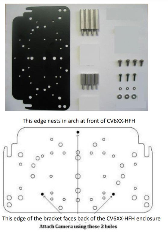
Hardware Pack Provided with CV6XX-HFH Housing
 |
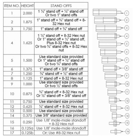
Stand-Off Height Assembly Table for Camera Height Adjustment
|
MVP Voltage Matrix: Enclosure Input – Camera Output
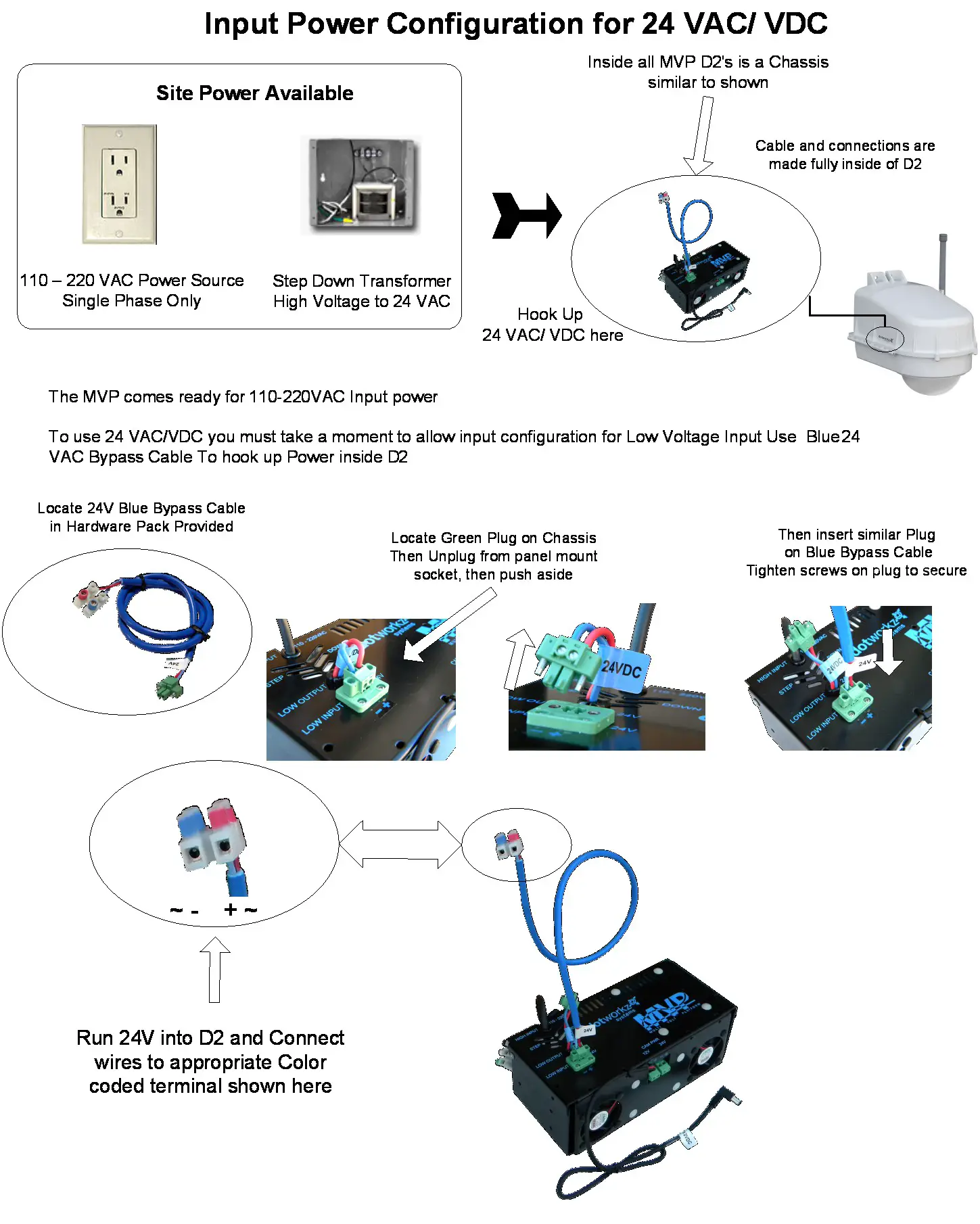
Input Voltage to EnclosureThe MVP Enclosures can be powered by Inputs of either High Voltage 110-220 VAC. Or Low Volt 24 VAC/ VDC
Voltage Matrix for Input / Output
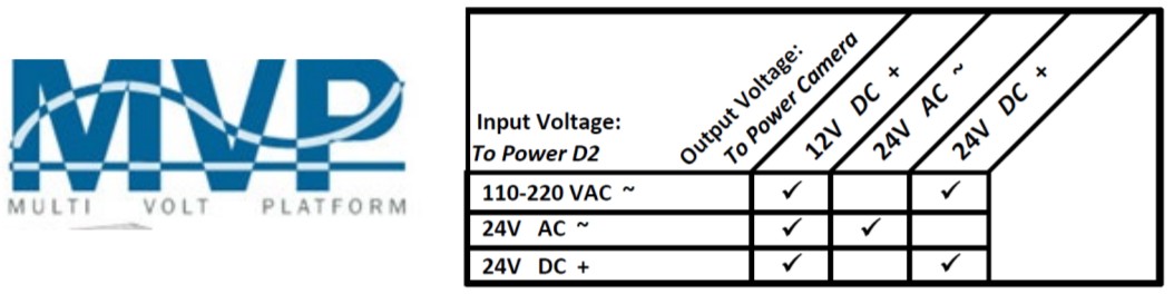
Output Voltage to Power CameraMVP provides step-down voltage to supply camera power for 12VDC and 24V Cameras. 24V Camera Supply24V output depends on Site Power Input, for either 24V Direct Current, or Alternating Current (see table above)
 Input SpecificationsInput Voltage: 90-264 VAC, (127-370 VDC)Frequency Range: 47- 63 HZInput Current @ Full Load(Typ.): , Recommended Min. Circuit Breaker: 6 A (type C)Int. Electrical. Working Temp’: -20 — +70CMTBF: 353.6Khrs min. MIL-HDBK-217F(25C)
High Voltage A/C Tvnical Conventions. single-phase (USA wiring convention)
| Color | Symbol | Description |
| Black | L | Line Conductor, aka “Hot” wire |
| White | N | Neutral Conductor |
| Green | G | Ground Wire, Chassis Ground |
Power Available to Camera & Accessories (max.)MVP using 110/ 220 VAC input to CV6XX-HFH
Using ONE Output
| Model | 12 VDC Output | OR | 24 VDC |
| Heater Blower | 25 watts | or | 25 watts |
| Tornado | 25 watts | or | 25 watts |
| Ring of Fire | 25 watts | or | 25 watts |
Using BOTH Output Channels (12VDC & 24VDC)
| 12 VDC Output | AND | 24 VDC | |
| (A) watts | + | (B) watts | 25 watts total |
| 25 watts max | + | 15 watts max | 40 watts total |
| (A) watts | + | (A) watts | 25 watts total |
Camera Power/Output Power for MVP

The MVP comes prewired with a 12VDC power cable ready to plug into some of the most common camera modelsHowever, if your camera has a different power need, the MVP can easily adapt to most camera power needsCamera Power Setup (STANDARD 12VDC CONNECTOR)All CV6XX-HFH environmental enclosures come standard with a 12VDC Right Angle Barrel Plug (3.3mm x 5.5mm with a 1mm center pin) for a majority of the IP cameras on the market.

If your IP camera’s power connector is different but still accepts up to – 13VDC for power, please see our section on Camera Power Setup (NON-STANDARD CONNECTOR) for instructions on how to power your camera.Below are pictures of typical NON-STANDARD CONNECTORS.

If your IP camera’s power requirements are for 24 VAC ONLY, please make sure that the CV6XX-HFH Environmental dome that you purchased is a 24VAC version.Cameras that run on 24VAC will not work with the /2VDC and 110-240VAC versions of our CV6XX-HFH Environmental domes.*NOTE: The only way a 24VAC camera will work on our 12VDC and the 110-240VAC dome is if you, the customer, provide a separate power lead into the dome for your camera.We have designed our domes to be sin and efficient when it comes to powering our environmental component and camera So when comes to cameras with 24VAC power require rods, we –RECOlVIVF_ND- the 241/A C versions of our Environmental domes for proper installation.
Camera InstallationThe CV6XX-HFH Enclosure series can accommodate mini-domes and PTZ cameras as tall as 9.375 inches in height. Our standoff combination includes supported heights of 0.50″, 0.74″, 1.00″, 1.25″, 1.50″, 1.75″, 2.00″, 2.25″, 2.50″, 2.75″, 3.00″, and 3.75″. These standoff heights can be applied to upper and lower mount locations based on the height of your camera. Most cameras will often utilize a center screw hole for securing the camera onto the plate.
 If your camera has other mounting capabilities, then center the camera on our camera bracket and check to see if it aligns with any of the pre-made holes on the camera bracket If it does, great you can use the pre-made holes. If it doesn’t, you can mark the holes needed and drill them into the camera plate (steel plate).For power, all of our CV6XX-HFH Environmental Enclosure Series come standard with o 12VDC Barrel plug with a center pin. if your camera does not support this, then check our section on Camera Power Setup (NON-STANDARD CONNECTOR) for details.
Installing Camera BracketIn order to mount the CV612/CV620/CV630 CAMERA, you must install the P17 cameras included Ceiling Mount (CV620-CM-KIT) This will allow for hole alignment on the CB-1007 V4 MOUNTING PLATE.
- Install the PTZ camera onto the CV6XX-HFH Camera Bracket with (3) m3-.5, (3) m3 external lock washers, and (3) m3 1/8″ washers that is included.
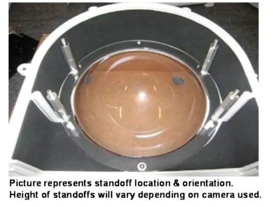
- The P17 camera requires a 2.25″ spacing for optimal fit and operation. Use (1) 1.5″ standoffs and (1) .75″ standoff that are provided to create a 2.25″ standoff. You will need to create 4 of these with the included. hardware.

- The 2.25″ standoffs will be inserted on the upper portion of the CV6XX-HFH
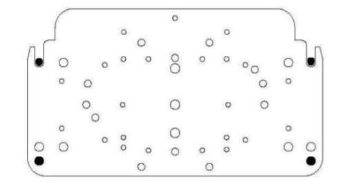
- Now slide the camera bracket with the camera into place to line up with 4 screws holes from the standoffs.
- Use (4) #8-32 screws (Phillips’s head) to secure the bracket into place.Tip: Insert (2) #8-32 screws in the front two standoffs to provide a guide to slide the camera bracket into. The last two corner holes should line up and be secured last.The picture represents camera bracket orientation & how it is secured. Don’t’ forget to mount your camera to the CV6XX-HFH camera bracket based on instructions.


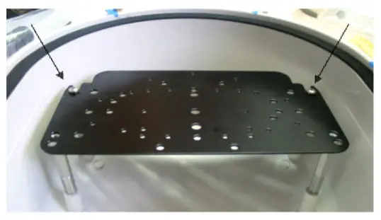 Tip: Insert (2) #8-32 screws in the front two standoffs to provide a guide to slide the camera bracket into. The last two corner holes should line up and be secured last.
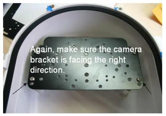 The picture represents camera bracket orientation & how it is secured. Don’t’ forget to mount your camera to the CV6XX-HFH camera bracket based on instructions.
Installing Camera BracketRequired components (see component checklist): Part# 1,2,3,5,6,7,& 8
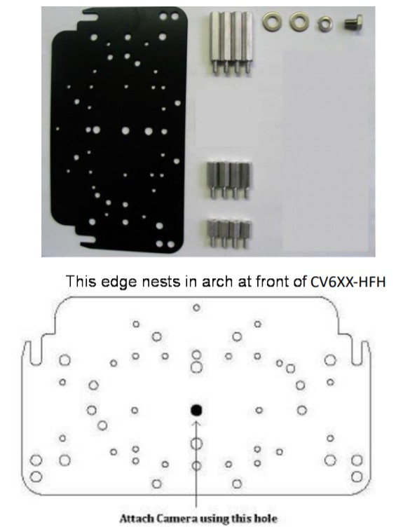
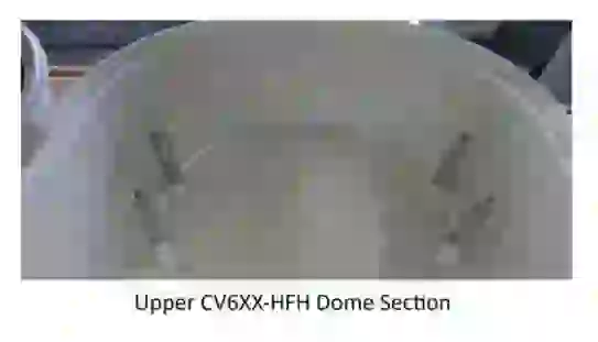
This edge nests in the arch in front of CV6XX-HFH
- Install the PTZ camera onto the CV6XX-HFH Camera Bracket center hole with (1) .25″-20 3/8″ Long Bolt, and (1) .25″ Lock Washer that is included.
- The PTZ camera requires a 2.0″ spacing for optimal fit and operation. Use (1) 1.5″ standoff and (1) .5″ standoff that is provided to create a 2.0″ standoff. You will need to create 4 of these with the included hardware.
- The 2.0″ standoffs will be inserted on the lower lens portion of the CV6XX-HFH
- Now slide the camera bracket with the camera into place to line up with 4 screws from the standoffs.
- Secure the plate by using (4) .75″ O 0 0 O 0 o standoffs to lock the bracket in place. The O 0 0 0 0 0 0 0 0 0 two front locations will require the use of (2) C2. o o 0 J .25″ washer.


- If wires, cabling, or conduit are coming at enclosure wire entry-level, or above, always create a drip loop
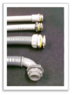
- Please use only approved watertight electrical conduit and connectors, IP66 or better, with proper seals and fittings Installed & fully seal.
- Then after all wire and cables are installed into the enclosure, Seal wire entry ports inside of the enclosure with any number of commercially available sealing putty, Silicone Sealant, or similar products that are approved by applicable local and relevant electrical codes.
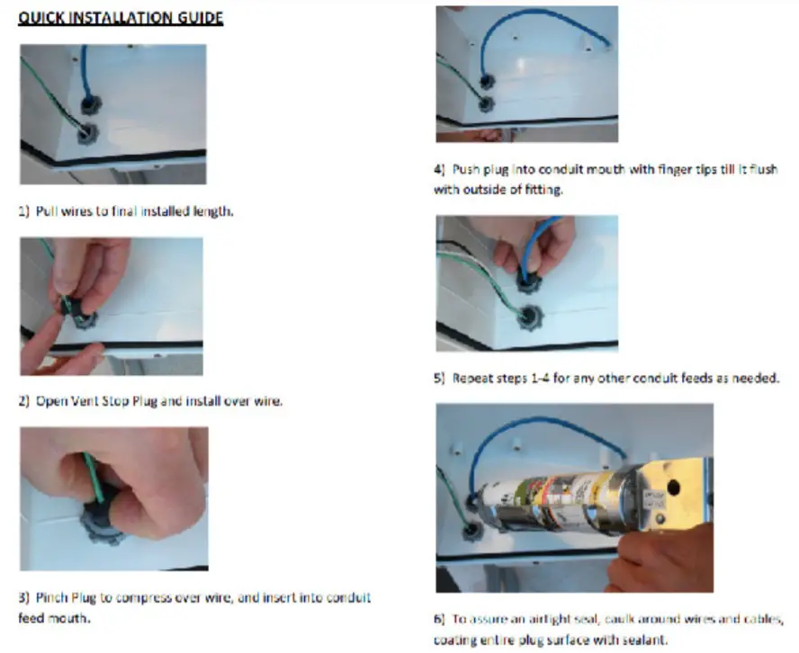
Marshall supplies two ½” diameter foam conduit plugs, that when installed, will assist in sealing off airflow in conduit feed-thru, at cable entry Inside of enclosure. Putty or Sealant can be used in conjunction with these plugs, to assure a full seal inside enclosure cable feed entry.
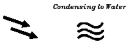
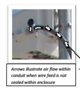
| WARM/MOIST IN UNSEALED CONDUIT MOVES THRU CONDUIT FEEDS EXPAND & CONTRACT WHEN CONDUIT HEATS & COOLS WITH OUTSIDE TEMPERATURES | EXPANDS* HEATED AIR IS PUSHED INTO ENCLOSURE THEN COOLS & It’ CONDENSES, FRANC MI CONDENSES ON SURFACES INSIDE ENCLOSURE |
 |
 |

Marshall does endorse, nor has it evaluated any of these products. Test products first, and follow all manufacturer’s instructions. Follow all applicable electrical and building codes and installation guidelines. End-user assumes liability for applicability of these products and their effectiveness and incurred liability in using these products.
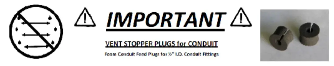 Conduit Feeds Must Be Sealed for Safe and Satisfactory Product Performance.
Conduit Stopper Plugs prevent Humid Air exchange from venting through the external conduit into Marshall sealed enclosure when the conduit is used with Marshall enclosures. Vent Stopper Plugs eliminate conduit-driven condensation in surveillance camera enclosures or other outdoor enclosure products.

![]() CV6XX-HFH Exploded Detail
CV6XX-HFH Exploded Detail
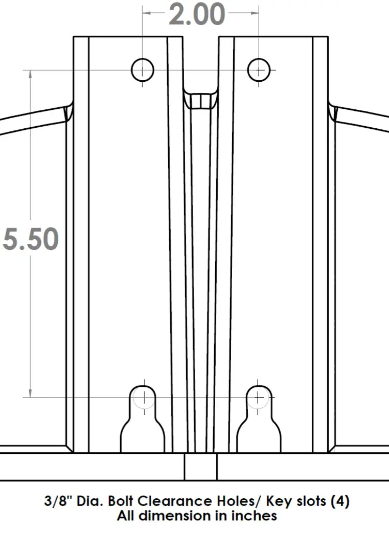
CV6XX-HFH Mounting Detail
Warranty
Marshall Electronics warranties to the first consumer that this device will, under normal use, be free from defects in workmanship and materials, when received in its original container, for a period of two years from the purchase date. This warranty is extended to the first consumer only, and proof of purchase is necessary to honor the warranty. If there is no proof of purchase provided with a warranty claim, Marshall Electronics reserves the right not to honor the warranty set forth above. Therefore, labor and parts may be charged to the consumer. This warranty does not apply to the product exterior or cosmetics. Misuse, abnormal handling, alterations, or modifications in design or construction void this warranty. No sales personnel of the seller or any other person is authorized to make any warranties other than those described above or to extend the duration of any warranties on behalf of Marshall Electronics, beyond the time period described above.Due to constant effort to improve products and product features, specifications may change without notice.
![]() 20608 Madrona Avenue, Torrance, CA 90503el: (800) 800-6608 / (310) 333-0606Fax: 310-333-0688www.marshall-usa.com[email protected]www.marshall-usa.com
20608 Madrona Avenue, Torrance, CA 90503el: (800) 800-6608 / (310) 333-0606Fax: 310-333-0688www.marshall-usa.com[email protected]www.marshall-usa.com
References
[xyz-ips snippet=”download-snippet”]