
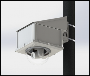
Marshall CV7XX-HFH Compact Weatherproof Dome Housing for PTZ w/Fan and Heater
PRODUCT INSTALLATION PRECAUTIONS – WARNINGS – ADDITIONAL INFORMATION
IMPORTANT SAFEGUARDS
- Read Instructions – All the safety and operating instructions should be read before the unit is operated.
- Retain Instructions -The safety and operating instructions should be retained for future reference.
- Heed Warnings – All warnings on the unit and in the operating instructions should be adhered to.
- Follow Instructions -All operating & user instructions should be followed.
- Electrical Connections – Only a qualified electrician should make electrical connections.
- Attachments – Do not use attachments not recommended by the product manufacturer as they may cause hazards
- Cable Runs – All cable runs must be within permissible distance
- Mounting -This unit must be properly and securely mounted to a supporting structure capable of sustaining the weight of the unit. Accordingly:a. Installation should be made by a qualified installer.b. Installation should be in compliance with local codesc. Care should be exercised to select suitable hardware to install the unit, taking into account both the composition of the mounting surface and the weight of the unit. Be sure to periodically examine the unit and the supporting structure to make sure that the integrity of the installations intact. Failure to comply with the foregoing could result in the unit separating from the support structure and falling, with resultant damages or injury to anyone or anything struck by the failing unit.
| AUTION: TO REDUCE THE RISK OF ELECTRICAL SHOCK, DO NOT EXPOSE COMPONENTS TO WATER OR MOISTURE | |
 |
The lightning flash with an arrowhead symbol, within an equilateral triangle, is intended to alert the user to the presence of non-insulated “dangerous voltage” within the product’s enclosure that may be of sufficient magnitude to constitute a risk of electric shock to persons |
 |
The exclamation point within an equilateral triangle is intended to alert the user to the presence of important operating and maintenance (servicing) instructions in the literature accompanying the appliance |
SERVICE
If the unit ever needs repair service, customer should contact Marshall Electronics (800-800-6608) for return authorization & shipping instructions.
UNPACKING
Unpack carefully. Electronic components can be damaged if improperly handled or dropped. If an item appears to have been damaged in shipment, replace it properly in its carton and notify the shipper. Be sure to save
- The shipping carton and packaging material. They are the safest material in which to make future shipments of the equipment.
- These Installation and Operating Instructions.
- For technical questions or product returns – call Marshall Electronics Customer Service (800-800-6608) 7:30 AM to 4:30 PM (PST). The proper technician will contact you as soon as possible.
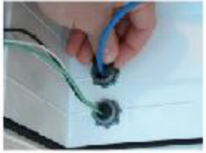
- The External Nut on All electrical wire feed Glands must be tightened to create a weather tight seal prior to putting CV7XX-HFH in service. Failure to create this seal may result in water incursion into enclosure. This may lead to electrical shock, product failure and damage to electrical systems installed within enclosure, including but not limited to damage to camera, heater and blower circuitry, cooling circuitry and other systems installed in unit.
- All screws supplied for hinged lower must be tightened to create seal on enclosure. Failure to create this seal may result in water incursion into enclosure. This may lead to electrical shock, failure and damage to electrical systems installed within enclosure, including but not limited to damage to camera, heater and blower circuitry, cooling circuitry and other systems installed in unit.
- Do not over tighten any Screws, Stand Offs, or other fasteners on this unit. Failure to heed this warning will cause damage or failure of the CV7XX-HFH enclosure.
- This installation requires a minimum of two people. Do not attempt to install this enclosure by yourself.
- Be sure to take extra care to protect domed (“bubble”) lens of unit prior to installation, during installation, and during service. Failure to protect lens will adversely affect product performance.
Required Hardware
Ensure that all required hardware is included before beginning the installation.
- 4 x 3/8-16 Concrete anchors, washers, and nuts, torque nuts to 247 in-lbs [27.9 Nm]
- 12 x 6-32 flat head screws (installed on unit), torque to 10 in-lbs. [1.1 Nm]
- 4 x 10-32 button head screws, torque to 30 in-lbs. [3.4 Nm]
- 2 x 1/4-20 socket head cap screw, nylon locking, torque to 78 in-lbs. [8.9 Nm
Mount Installation
Pendant Mount
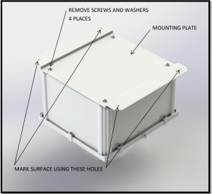
- Separate the Mounting Plate form the enclosure. Place hardware aside in a safe place for later re-installation.

- Hold the Mounting Plate up to the desired mounting location. Using the Mounting Plate as a template, mark the mounting surface at the location of the 4 indicated mounting holes for Drilling. Ensure that the holes are marked as accurately as possible. Set the Mounting Plate aside after marking the drilling locations.
- Use a hammer drill to make 3/8 inch diameter holes at each of the 4 mounting locations marked in the previous step. A hammer drill is required for this operation. Clean the holes of all concrete dust using a wire brush and compressed air or a vacuum. Install the 3/8-16 concrete anchors in each of the 4 drilled holes by hammering them in to the appropriate depth. Leave the nut on while hammering so that the threads of the concrete anchor are protected and not damaged. Ensure that the Mounting Plate fits over the concrete anchors, and then set it aside.
Warnings:
- The supplied anchors are for concrete only. Do not attempt to use in brick, block or other materials. Other fasteners are required for brick, block and other materials and are not included. Minimum engagement of the supplied concrete anchors is 2” [50 mm]. If the provided fasteners are not appropriate for the installation surface, it is the responsibility of the customer to specify and source appropriate fasteners for the application.
- Holes for concrete anchors should be drilled a minimum of 1/2 inch [13 mm] deeper than the overall length of the anchor, provided that the mounting surface can tolerate such a depth. This allows the anchor to be hammered flush should a mistake be made or a location change be necessary.
Wall Mount
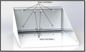
- Remove the Wall Mount Cover from the Wall Mount by unscrewing the four 6-32 flat head screws in the corners of the bracket system. Set the cover and four fasteners aside in a safe place for later use.
- Hold the Wall Mount up to the desired mounting location. Ensure that the mount is level and oriented properly in the correct location. Using the Wall Mount as a template, mark the 4 mounting holes for drilling. There are two suitable mounting patterns to allow for installation flexibility, as indicated below. With the hole locations marked, set the Wall Mount aside for later use.
- Use a hammer drill to make 3/8 inch diameter holes at each of the 4 mounting locations marked in the previous step. A hammer drill is required for this operation. Clean the holes of all concrete dust using a wire brush and compressed air or a vacuum. Install the 3/8-16 concrete anchors in each of the 4 drilled holes by hammering them in to the appropriate depth. Leave the nut on while hammering so that the threads of the anchor are not damaged. Ensure that the Wall Mount fits over the concrete anchors, and then set it aside.

Warnings:
- The supplied anchors are for concrete only. Do not attempt to use in brick, block, or other materials. Other fasteners are required for brick, block and other materials and are not included. Minimum engagement of the supplied concrete anchors is 2” [50 mm]. If the provided fasteners are not appropriate for the installation surface, it is the responsibility of the customer to specify and source appropriate fasteners for the application.
- Holes for concrete anchors should be drilled a minimum of 1/2 inch [13 mm] deeper than the overall length of the anchor, provided that the mounting surface can tolerate such a depth. This allows the anchor to be hammered flush should a mistake be made or a location change be necessary.
Pole Mount
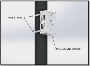
- Install the BR-MPM1, BR-MPM2 or KT-CDR2 pole mount bracket system on the desired pole at the appropriate height using pole strapping or hose clamps. Pole straps are not included and are the responsibility of the customer to source for their particular application.
Enclosure Preparation
- Install the camera manufacturer supplied ceiling mount bracket (typically twist-to-lock) onto the black Camera Bracket inside the enclosure. The black bracket inside the enclosure is designed to accept typical ceiling mount brackets via four M4 fasteners and four M4 nylon locking nuts.If this hardware cannot be sourced, the camera can also be directly installed using the supplied 2 x 1/4-20 socket head cap screws from the hardware kit. Using the camera manufacturer supplied “mount bracket” is highly recommended to minimize overall weight while the enclosure is being lifted for mounting.
- Install the supplied domed lens on the hinged lid of the enclosure. Remove the 12 x 6-32 flat head screws and set aside in a safe place for reinstallation. Remove the metal retaining ring to expose the seal. Remove the protective film from the domed lens and align the mounting holes of the dome with the holes in the gasket. Place the retaining ring over the domed lens and align the holes of the retaining ring with the mounting holes in the domed lens. Reinstall the twelve 6-32 flat head screws and torque them to the appropriate value, making sure to alternate from one side of the lens to the other when tightening the 12 screws to minimize stresses in the domed lens.
- Plan your cable management before installing the enclosure. Pay particular attention to bend radii and sealing of cable glands. The cable glands installed on the enclosure can be used as plugs or break through, multi-hole glands for smaller diameter cables. The cable glands provided in the hardware kit are designed to accommodate 1 cable per cable gland. The cable diameters accommodated are 4.3 mm – 11.4 mm. Other cable diameters will require alternative cable glands to create an environmental seal. It may be required to cut connectors off of terminated cables and re-terminate a connector on the opposite side of the gland if a connector does not fit through the prescribed gland.

Enclosure Installation
- Install the Mounting Plate or Wall Mounting Bracket on the CV7XX-HFH Enclosure using four 1/4-20 fasteners and washers.
- Without the camera installed, bring the enclosure up to the mounting location. Warnings:● The enclosure weighs 32 lbs. [15 kg] without a camera installed. The final mounting of the enclosure requires a minimum of 2 people to complete in a safe manner. Do not attempt to complete this step by yourself.● If the manufacturer provided camera mounting plate is not being used for camera mounting, it may be easier to mount the camera inside the enclosure before bringing the enclosure up to the mounting surface.
- Secure the enclosure to the mounting surface by tightening the nuts on the concrete anchors, screwing the enclosure to the pole mount, or by using alternative fasteners that are appropriate for the installation. Ensure appropriate torque is applied to each fastener. A thread locking compound is recommended for these connections.
- Install the camera in the enclosure using the manufacturer provided “twist- to-lock” mounting plate. If the camera manufacturer does not supply a “twist-to-lock” mounting plate, use the 2 x 1/4-20 fasteners that were supplied (see 4.5). This is more easily achieved prior to mounting the enclosure.
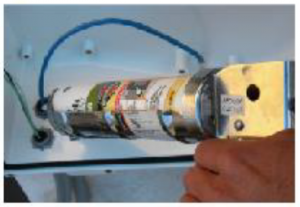
- Establish all video and communication connections to the camera before applying power. Once all other lines are connected, connect the coaxial power cable from the Marshall electronics to the camera. This cable is included and connected to a 12VDC source.
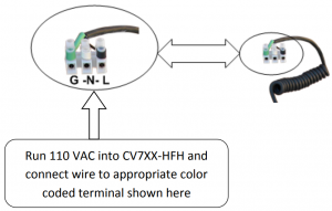
- Connect line power to the Marshall electronics via the supplied terminal that is marked black (hot), white (neutral) and green (protective ground). This will provide power to the environmental controls and to the camera.
High Voltage A/C Typical Conversions, single phase (USA wiring conversion) Color Symbol Description Black L line Conductor, aka! “Hot” Wire White N Neutral Conductor Green G Ground Wire Chassis Ground Warning● Only a certified electrician should make electrical connections. The above listed electrical connections may contain dangerous voltages. Only professionally trained electricians should interface with electrical components. - Test camera functionality to ensure proper operation of the unit.
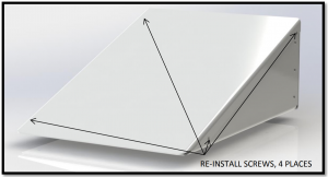
- Close the lid of the enclosure and engage the 4 latches at the 3 unhinged edges. Install the four 10-32 button head screws through the 4 corners of the lid to ensure adequate long term sealing.
- If a Wall Mount is used, re-install the Wall Mount Cover onto the Wall Mount by using the four 6-32 flat head screws.
Electrical Conduit Guidelines
The below information applies to the CV7XX-HFH and should be followed strictly.
Electrical Conduit Guidelines
For optimal performance, your CV7XX-HFH is designed to be air and water tight to eliminate any moisture, dust, and insect damage
use of Electrical Conduit, without sealing the entry parts/ inside wire feeds within Camera Enclosure, will subject the inside of your enclosure to possibility of condensation driven moisture, dust and insect contamination hazards. Always follow local and national electrical codes for installation. Installation should always be done by a qualified service technician.
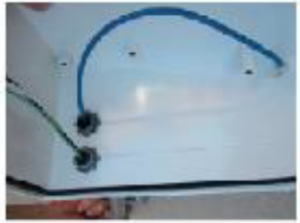
Marshall has provided each CV7XX-HFH with two Cable Gland Strain Relief seal ports that fully seal enclosure to IP68 rating, Waterproof, and Airtight Seal. (holes on enclosure are 7/8” diameter, ready for standard 1/2” I.D. NPT Connector, or PG13 fittings.)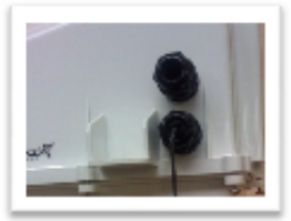
However, we realize our customers are retrofitting these connectors with electrical conduit fittings. We acknowledge this industry customization and installation practice, and would like to make these suggestions for customers to property inst.al these products.
Conduit suggestions:
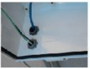
- If wires, cabling, or conduit are coming at enclosure wire entry level, or above, always create a drip loop.
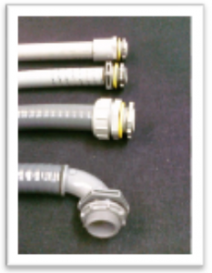
- Please use only approved watertight electrical conduit and connectors, IP66 or better, with proper seals and fittings Installed & fully seal.
- Then, after all wire and cables are Installed into enclosure,, Seal wire entry ports inside of enclosure with any number- of commercially available sealing putty’s, Silicone Sealant, or similar products that are approved by applicable local and relevant electrical codes.
Marshall supplies two 1/2” diameter foam conduit plugs, that when installed, will assist in sealing off airflow in conduit feed thru, at cable entry inside of enclosure. Putty or sealant can be used in conjunction with these plugs, to assure a full seal inside enclosure cable feed entry.
FORCES AT WORK IN ANY UNSEALED, CONDUIT WIRE FEED ENCLOSURE SYSTEM
WARM/MOIST IN UNSEALED CONDUIT MOVES THRU CONDUIT FEEDS EXPAND & CONTRACT WHEN CONDUIT HEATS & COOLS WITH OUTSIDE TEMPRATURES ![]() EXPANDING HEATED AIR IS PUSHED INTO ENCLOSURE THEN COOLS & CONDENSES, HUMID AIR CONDENSES ON SURFACE INSIDE ENCLOSURE
EXPANDING HEATED AIR IS PUSHED INTO ENCLOSURE THEN COOLS & CONDENSES, HUMID AIR CONDENSES ON SURFACE INSIDE ENCLOSURE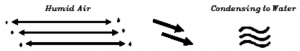
SHOCK HAZARD!hazard unsatisfactory in the CV7XX-HFH product, electronics due to air collecting in enclosure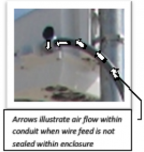
Failure to fully seal enclosure wire and cabling entry parts may lead to shock product performance, a possibility of damage to electronics including camera damage, and damage to integrated driven moisture travelling thru the conduit, condensing an d creating a short circuit hazard.
Marshall does not enclosure, nor has it evaluated any of these products first, and follow all manufacturers’ instructions, Follow all applicable electrical and building codes and installation guidelines. End user assumes liability for applicability of these products and their effectiveness and incurred liability in using these products.
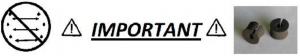
VENT STOPPER PLUGS for CQNDUITFrom Conduit Feed Plug for 1/2” ID. Conduit Fittings
Conduit Feeds Must Be Sealed for Safe and Satisfactory Product Performance.
Conduit Stopper Plugs prevent Humid Air exchange from venting thru external conduit into Marshall sealed enclosure, when conduit is used with Marshall enclosure. Vent Stopper Plugs eliminate Conduit condensation in surveillance camera enclosures, or other outdoor enclosure products.
QUIR INSTALLATION GUIDE
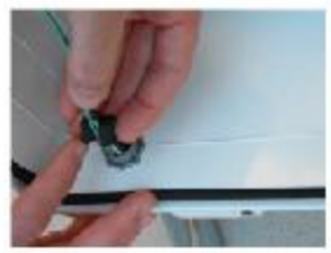
- Pull wires to final installed length.
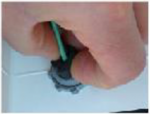
- Open vent Stop Plug and install over wire.
- Pinch Plug to compress over wire, and insert into conduit feed mouth.
- Push plug into conduit mouth with outside of fitting.
- Repeat steps 1-4 for any other conduit feeds as needed.
- To assure an airtight seal, caulk around wires and cables coating entire plug surface with sealant.
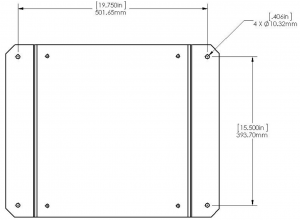
Mounting Detail
These are the mounting dimensions for the CV7XX-HFH Enclosure. See Section 2 for recommended steps to follow.
Warning: It is recommended to use the Mounting Plate or Wall Mount as a template for marking drill locations. This helps account for fabrication tolerances in the mounting plate.
Pendant Mount
Wall Mount

![]()
[xyz-ips snippet=”download-snippet”]