MASTECH Thermocouple Calibrator User Manual
Introduction
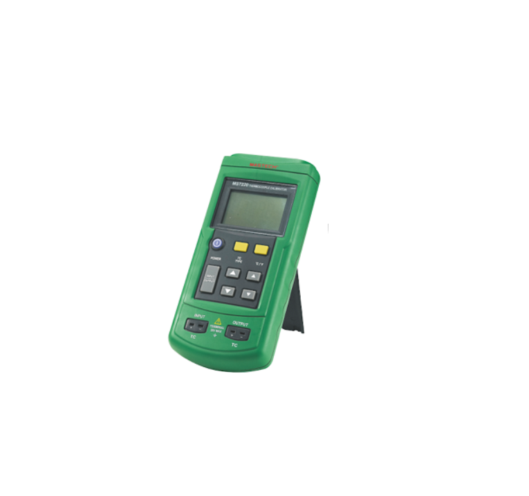
The Thermocouple Calibrator is a precise source and measurement tool for calibrating thermocouple instruments. The calibrator sources or measures in units of °C,°F, or mV, through a thermocouple minijack. If the calibrator is damaged or something is missing, contact the place of purchase immediately. Contact your distributor for information about accessories.The following tables list the thermocouple types supported by the calibrator, the standards and scales used for each type, the thermocouple properties, and calibrator resolution.
NoteSince mV input and output units are available, you can use the calibrator for any thermocouple type by making manual calculations or referring to tables.
Thermocouple Standards and Scales
| Thermocouple Type | Standard | Scale |
| J, K, T, E, R, S, B, N | NIST 175 | ITS-90 |
Thermocouple Properties
| Thermocouple Type | Temperature Ranges | Display Resolution |
|
J |
-200~1200°C/-328~2192°F | 0.1°C or°F |
|
K |
-200~1370°C/-328~2498°F | 0.1°C or°F |
|
T |
-200~400°C/-328~752°F | 0.1°C or°F |
|
E |
-200~950°C/-328~1742°F | 0.1°C or°F |
|
R |
-20~1750°C/-4~3182°F | 1°C or°F |
|
S |
-20~1750°C/-4~3182°F | 1°C or°F |
|
B |
600~1800°C/1112~3272°F | 1°C or°F |
|
N |
-250~1300°C/-418~2372°F | 0.1°C or°F |
Millivolt Range and Resolution
| Mode | Range | Display Resolution |
| mV | -10mV~75mV | 0.01mV |
Safety Information
Warning
To avoid possible electric shock or personal injury:
- Never apply more than 30 V between the TC terminals, or between either TC terminal and earth ground.
- Make sure the battery door is closed and latched before you operate the calibrator.
- Remove an attached thermocouple miniplug from the calibrator before you open the battery door.
- Do not operate the calibrator if it is damaged.
- Do not operate the calibrator around explosive gas, vapor, or dust.
When servicing the calibrator, use only specified replacement parts.
Explanation of International Symbols
The following symbols are used on the calibrator or in this instruction sheet. The table below explains their meaning
International Symbols
| Symbol | Meaning | ||
 |
Earth ground | ||
 |
Refer to this instruction manual for information about this feature |
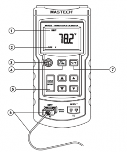
Operation:
Measuring a Thermocouple
- INPUT.
- Shows TC type
- Press to select ON or
- Press to select TC type or
- Press so that INPUT is on the
- TC wire and miniplug of same type as
Press to toggle °C or °F.
Simulating a Thermocouple
- OUTPUT.
- Shows TC type
- Press to select ON or
- Press to select TC type orPress so that OUTPUT is on the display.
- Press to step up/down 10°or 1mV.
- Press to toggle °C or °F
- Press to scroll up/down 0.1°or 0.01mV. Hold down to scroll faster.
- TC wire and miniplug of same type as selected

Specifications
Specifications are based on a one year calibration cycle and apply for ambient temperature from + 18°C to +28°C unless stated otherwise. “Counts” means number of increments or decrements of the International Symbols least significant digit
Temperature Measure and Thermocouple Simulate(Maximum input voltage:30V)
| Thermocouple Type | Resolution | Error | Reference Junction Error |
| J, K, T, E, N | 0.1°C or °F | ±(0.3°C+10μV) | ±0.2°C |
| R, S, B | 1°C or °F | ±(0.3°C+10μV) | ±0.2°C |
Maximum input voltage: 30 V
Millivolt Measure and Source(Maximum input voltage:30V)
| Range | Resolution | Accuracy |
| -10mV~75mV | 0.01mV | ±(0.02%+2Dgt) |
Maximum input voltage: 30 V
General SpecificationsMaximum voltage applied between any terminal and earth ground or between any two terminals: 30V Storage temperature :-40°C to 60°C Operation temperature:-10°C to 55°C Operation altitude: 3000 meters maximum Temperature coefficient: 0.05×specified accuracy per°C for temperature ranges -10°C to 18°C and 28°C to 55°C
Relative humidity:95% up to 30°C,75% up to 40°C, 45% up to 50°C,and 35% up to 55°C Vibration: Random 2 g,5 Hz to 500 Hz Shock: 1 meter drop test Power requirements: Single 9V battery (ANSI/NEDA 1604A or IEC 6LR61) Size: 190mm L×89mm W×42mm H Weight: Approx. 367g
MaintenanceIf the calibrator needs repair, contact your Service. If the calibrator is under warranty, see the warranty statement for terms. If the warranty has lapsed, thecalibrator will be repaired and returned for a fixed fee. Contact your Service Center for information and price.
CleaningPeriodically wipe the case with a damp cloth and detergent; do not use abrasives or solvents.
CalibrationCalibrate your calibrator once a year to ensure that it performs according to its specifications.
Replacing the BatteryWhen the symbol appears on the display, replace the battery with a 9V alkaline battery. Replacing the Fuse Fuse is probably blown if in the input mode, the calibrator always reads OL, even with a thermocouple connected.
Read More About This Manual & Download PDF:
[xyz-ips snippet=”download-snippet”]