Master Stat 110423-2 Wall Control Thermostat Instruction Manual
Installation Instructions
CAUTION: Failure to read and follow all installation and operating instructions could lead to personal injury and/ or damage to property.
CAUTION: All electrical installations must comply with local building and safety codes and must be performed by qualified personnel only.
System Overview
- This control system is intended to be used with an evaporative cooler with a 2-speed blower and a water pump. It will also operate a water purge pump or valve, if equipped.
- The control is designed for fan motors up to 1HP (120V) or 2HP (240V), with water pump and purge pump up to 2A (120V) or 1A (240V)
- The fan motor may be 120V or 240V rated.
- The water pump and purge pump motors/valves share the same electrical supply, rated for 120V or 240V.
Included in Kit
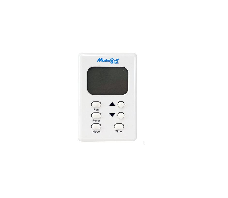
- Wall Control Thermostat
- 2-Speed Evaporative Cooler Control
- Wire Nut for common Earth connection.
- Spare 3.15 Amp fuse for control.
- Jumper wire for Link to N-Link (To be used only when both Fan and Pump voltages are the same).
Additional RequirementsDepending on application and installation, the following additional items may be required:
- Screws or bolts for mounting the Appliance Control Box and Wall Control
- Wiring for connection between power supply and Appliance Control Box; Wall Control and Appliance Control Box; and between Appliance Control Box and the cooler connection box.
- Conduit and watertight connectors to protect all wiring.
Installation of the Appliance Control BoxCAUTION: To prevent electrical shock and/or damage to the equipment, disconnect electrical power to the system at the main fuse or circuit breaker before starting the installation, and leave disconnected until the installation is complete.
1) After determining a suitable place to install the Appliance Control Box inside the evaporative cooler, mark the location of the three mounting points (with the ‘TOP’ indication uppermost) and drill pilot holes for the mounting screws.2) Determine which knockout locations will be used for the system wiring.3) Using a suitable tool, cut out the required knockouts. Make sure to cut out the correct size hole for your fitting.4) Mount the box using suitable screws.5) Install conduit and connections, ensuring a watertight seal, especially around the locations where the knockouts were removed.6) Run wiring, in accordance with local and national electrical codes, to suit the installation.7) Connect the wires in accordance with the wiring diagram on next page (wiring diagram also located on the inside lid of Appliance Control box).WARNING: Use the jumper wire between Link and NLink only when fan and pump voltages are the same.
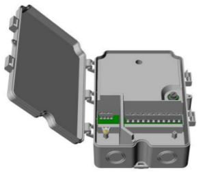
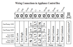
Note: Use the provided wire nut to connect all ground connections for power supply, fan, pump, purge pump and cooler cabinet.
Installation of the Wall Control – cavity wall without outlet box
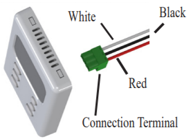
1) Determine a suitable place to install the Wall Control inside the building (away from sources of heat, sunlight, or ventilation, and between 4 and 6 feet from the floor). Do not install near cooler opening.2) Using the mounting plate as a guide, mark the location of the two mounting points and the terminal opening for the connection terminal.3) Make a hole in the wall just large enough to accommodate the connection terminal and associated wiring.4) Route an insulated three-conductor thermostat cable (or similar low voltage cable) from the Appliance Control Box through the hole, leaving about six inches protruding.5) Route the wiring through the opening in the wall control mounting plate. Using wall anchors, screw the mounting plate to the wall.6) Connect the wires to the terminals as per the wiring connection diagram below. These same wire colors match those indicated on the control box.7) Plug the connection terminal into the back of the wall control. Place the tabs on the mounting plate into the holes in the top of the thermostat and rotate the Wall Control until it snaps onto the mounting plate. You may use the provided screw to secure it in place.
Installation of the Wall Control – using an existing wall-mounted outlet box
CAUTION: Only use a single outlet box and do not share wiring with any other equipment.1) Route an insulated three-conductor thermostat cable (or similar low voltage cable) from the Appliance Control Box to the outlet box, leaving about six inches protruding.2) Route the wiring through the opening in the wall control mounting plate. Screw the mounting plate to the outlet box.3) Connect the wires to the terminals as per the wiring connection diagram below. These same wire colors match those indicated on the control box.4) Plug the connection terminal into the back of the wall control. Place the tabs on the mounting plate into the holes in the top of the thermostat and rotate the Wall Control until it snaps onto the mounting plate. You may use the provided screw to secure it in place.

Operating Instructions
Automatic OperationThe fan and water pump are controlled automatically to achieve the desired comfort level.Automatic operation is activated by pressing the ‘Mode’ button until ‘Auto’ is displayed on the LCD. The ‘Mode’ button changes the control between Off, Auto and Manual.The Set temperature (the target temperature for the control) may be altered by repeatedly pressing or holding the ‘Up’ and ‘Down’ buttons. The LCD will display ‘Set’ rather then ‘Room’ temperature for a short time after pressing the ‘Up’ or ‘Down’ button.On starting, if the pads in the cooler are too dry, the fan may be delayed from starting until the pads have absorbed some water. This is called Pre-Wet and lasts for 2 minutes, indicated by ‘Pre-Wet” flashing on the LCD. The Pre-Wet can be bypassed by entering manual mode by either pressing the ‘Fan’, ‘Pump’ or ‘Mode’ button and then pressing the ‘Mode’ button until ‘Auto’ is displayed.During automatic operation, the control performs a water purge cycle every 8 or 12 hours of pump operation. This interval can be toggled between 8 or 12 hours by simultaneously holding the ‘Pump’ and ‘Fan’ buttons for 5 seconds. The selected interval is displayed for a short time. Press the Up or Down arrow buttons to change between 8 or 12 hours. This action also starts a manual purge cycle. A purge pump or purge valve, which is not supplied with the thermostat control or evaporative cooler, is required for this operation.
Manual Operation
The fan speed and pump are set by the user.To activate the manual mode from the ‘Off’ state, press the ‘Mode’ button until ‘Manual is displayed. If the control is in the ‘Auto’ mode, you can change to manual mode by pressing either the ‘Mode’, ‘Fan’ or ‘Pump’ buttons. Each press of the ‘Fan’ button changes the fan to High, Low or Off. Each Press of the ‘Pump’ button changes the pump status either On or Off.The LCD will display ‘Manual’ on the left and the fan and pump settings on the right. The fan speed will be displayed as ‘Fan Hi’ or ‘Fan Lo’. If neither are displayed the fan is off. With the fan and pump both running ‘Cool’ will be displayed. If only the fan is running ‘Vent’ will be displayed. If only the pump is running ‘Pre-Wet’ will be displayed.
Time Delay OperationDelayed start or stop in ‘Auto’ or ‘Manual’ modeThe ‘Timer’ button is used to set a delay period between 1 and 12 hours in 1 hour increments.If the cooler is operating (in ‘Auto’ or ‘Manual’ modes) when the ‘Timer’ button is pressed, the delay period determines when the cooler switches off.If the cooler is off when the ‘Timer’ button is pressed, the delay period determines when the cooler starts in ‘Auto’ mode. The Set Temperature will be the last setting when running in ‘Auto’ mode.‘Timer Delay’ and the remaining time are displayed on the LCD while the timer feature is activated.You can cancel the Timer function at any time by pressing the ‘Timer’ button. The ‘Timer Delay’ indicator will no longer display on the LCD.
In the event of a power outageWhen power is restored after a power failure, the thermostat will resume operation in the mode selected prior to the power outage.Temperature adjustmentPress the up and down arrow buttons simultaneously for 3 seconds. Using the up or down arrow buttons you may adjust the room temperature plus or minus 3 degrees from the set point. This will allow for small adjustments in the temperature displayed on the LCD.
Trouble Shooting Guide
The guide below is intended to aid an Installer or Service Technician in resolving simple problems. CAUTION: To prevent electrical shock and/or damage to the equipment, disconnect electrical power to the system at the main fuse or circuit breaker before opening the appliance control box, and leave disconnected until after the lid has been shut and secured.CAUTION: Any testing performed on live conductors must be carried out by qualified personnel only.
| Observation | Possible Cause | Remedial Action |
| Cooler does not work / No LCD display on the Wall Control | Incorrect connection of wiring between Wall Control and Appliance Control Board | Check the correct connection of the three wires at the Appliance Control Board and Wall Control. Ensure the correct wiring order at both ends, and that the terminals are correctly fitted and secured |
| Power Supply Circuit Breaker Off or Appliance Control Box not connected to the Power Supply. | Check the condition of Power Supply Circuit Breaker. Verify that the circuit Breaker Switch is On.
Supply Voltage should be present between Supply L1 and Supply N terminals on the Appliance Control Board. |
|
| Blown Fuse in the Appliance Control Box. | Check the condition of Fuse located on the Appliance Control Board. Check for incorrect wiring. Replace blown fuse with the correct type. | |
| Appliance Control Board or Wall Control faulty. | Switch on the Power supply to the Appliance Control Box.
Measure the DC Voltage at the Wall Control between the Black and Red termi- nals with the Wall Control still connected. If the measured voltage is greater than 3.0VDC and the LCD remains blank, the Wall Control is at fault. If the voltage is less than 3.0VDC, disconnect the red wire and measure the voltage between the black and red wire. If the measured voltage rises to 3.0VDC, the Wall Control is faulty. If the measured voltage remains low, the Appliance Control Board is at fault. |
|
| Water/Purge Pump does not work. LCD on Wall Control indicates it is on. (*) | Poor connection of Water Pump termi- nals on the Appliance Control Board. | Verify that Water Pump leads are correctly connected to the Water Pump con- nection screw terminals on the Appliance Control Board. |
| Incorrect connection of wiring between Wall Control and Appliance Control Board. | Verify that colors of thermostat cable match the color description on Appliance Control Board. Check that all wires are firm and secure. | |
Fan Motor does not work
 report this ad report this ad/ No Fan High and/or Fan Low operation (*) |
Pre-Wet cycle is active | Check LCD display for flashing Pre-Wet indicating the fan is turned off until pre-wet cycle is complete. |
| Poor connection to Fan Motor termi- nals on the Appliance Control Board. | Verify that Fan Motor leads are correctly connected to the Fan Hi, Fan Lo, and N connection screw terminals on the Appliance Control Board. | |
| Incorrect connection of wiring between Wall Control and Appliance Control Board. | Verify that colors of thermostat cable match the color description on Appliance Control Board. Check that all wires are firm and secure. | |
| Poor connection between Link and Nlink | Verify that the jumper wire across “Link” and “Nlink” is connected properly. Warning: Use the jumper wire only when fan and pump voltages are the same. | |
| *Appliance Control Board Diagnostic Test | The Control Board contains diagnostic buttons in the upper left recessed section. Follow the instructions of the label lo- cated on the inside box cover to diagnose the different functions of the board. Pressing the buttons will test each function of the board. If all LED’s light during the test, the control board is working properly. If not the control board is faulty. |
Read More About This Manual & Download PDF:
[xyz-ips snippet=”download-snippet”]