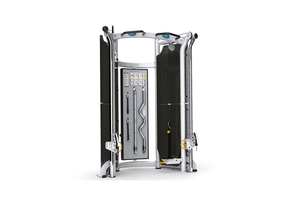
MATRIX G3MS20 Adjustable Cable Crossover Instructions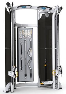
Prepared By: Brian Nelson, Dakota Freeman, John Guld & Regina Templeton
Time Required: 20 Minutes
Service Bulletin: Aura Cable Cross Adjustable Pulley Hardware Upgrade (Accompanying video: https://youtu.be/ucayW2hdD9U)
Date Prepared: April 8, 2021
Models Affected:G3MS24, G2/G3MS20, G2/G3MS40, G2/G3MS50 & G2/G3MS80
Overview
The hardware and procedure to attach the pulley housing to the handle on an Aura Cable Cross Adjustable Pulley station has changed. G2 and G3 Multi-Station Adjustable Pulleys that were manufactured between February 2005 and January 2019 should be upgraded to the new design. This does NOT include Functional Trainers.
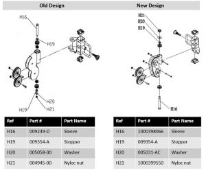
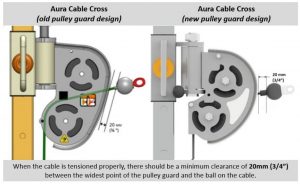
(The pulley housing design has also changed, as shown below, but both housing designs are acceptable.)
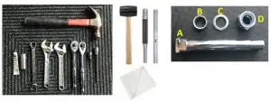
Required Tools
- Hammer
- Super Lube with PTFE grease
- 17mm deep well socket
- Two medium adjustable wrenches (or two 17mm open-end wrenches)
- Two ratcheting wrenches with 4mm Allen sockets (or two 4mm Allen keys)
- Rubber mallet
- Punch
- Ruler
- Rag
- Kit 1000461149

Hardware to Remove

- Sleeve
- Stopper x2
- Washer
- Nyloc nut
Hardware to Install
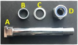
Kit 1000461149 contains:
- A – Sleeve: part # 1000398066
- B – Stopper: part # 009354-A
- C – Washer: part # 005031-AC
- D – Nyloc nut: part # 1000399550
Procedure
Remove the Old Hardware and Adjustable Pulley
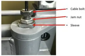
- Move the adjustable pulley to a comfortable height to work on it. Loosen the jam nut, then turn the cable bolt out to disconnect the cable from the sleeve.
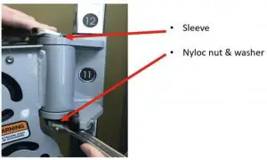
- Use one wrench to hold the sleeve in place while using the other wrench to remove the nyloc nut and washer from the sleeve.
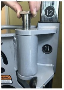
- Use a hammer to tap the sleeve upward. Remove the sleeve.
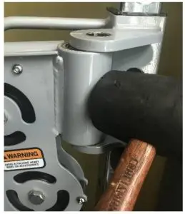
- Remove the pulley housing from the handle. You may need to use a rubber mallet to get it started. Do not use a metal hammer or you will damage the paint.Put your hand under the adjustable pulley as you remove it from the handle to hold the hardware in place/prevent it from falling out the bottom.Note: If the hardware does fall out, see the instructions in Step 8 for the order in which to reassemble it.
- Use the 17mm deep well socket and a hammer to remove the two stoppers. Pound the top stopper down and the bottom stopper up to remove them.
Prep the Adjustable Pulley
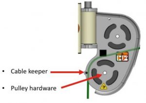
- Use the two 4mm Allen keys to remove the bottom cable keeper from the adjustable pulley. Then use the two wrenches to remove the bottom pulley hardware. Remove the pulley from the housing.Install the New Hardware and Adjustable Pulley
- Spread a dab of grease on the new stopper. Use the 17mm deep well socket to hammer it into the top hole. Stop when the stopper is flush with the surface on the inside.
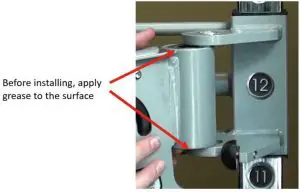
- Add grease to the top and bottom of the adjustable pulley housing. Install the adjustable pulley back into the handle.Note: If the hardware from inside the adjustable pulley falls out clean, grease, then reinstall the hardware in the order shown below. The side shown facing up should be turned over and installed downward into the adjustable pulley.
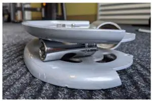
- Lay the adjustable pulley on its side and push the 17mm deep well socket into the pulley housing to make the sides flare. This creates more room to install the sleeve in the next step.
- Pick up the adjustable pulley, making sure to hold in the hardware at the bottom. Slidethe pulley into place on the handle.
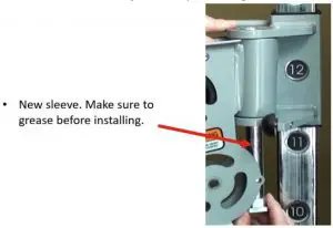
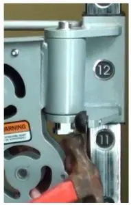
- Grease the new sleeve and install it from the bottom to fasten the pulley to the handle.Important: It may feel like the sleeve is too big to fit though the bottom bushing (as shown below). Use a hammer to help drive the sleeve through the bottom, and then through the top bushing. (The deep well socket—still inside of the housing—should allow enough room for the sleeve installation. If the pulley housing is still in the way and it is difficult to hammer the sleeve directly, use a punch against the sleeve.)
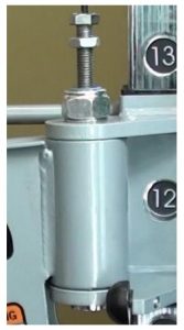
- Stop hammering when you see a few threads of the sleeve showing at the top.
- Remove the socket from the pulley housing.
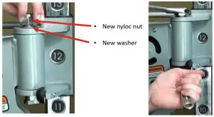
- Install the new washer and new nyloc nut on the sleeve. Place the nyloc nut so that the blue side faces up. Hold the sleeve at the bottom and tighten the nut with a wrench until one thread is showing through the top of the nut.
- Install the cable bolt on the new sleeve, just enough to keep it in place. (You will tension the bolt correctly in Step 17.)
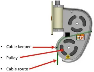
- Put the pulley back in place inside the housing and secure it with the hardware. Then, reinstall the cable keeper. Make sure to route the cable on top of the pulley, but under the cable keeper, as shown below.Tension the Cable Bolt
- Tension the cable bolt following the procedure below.Important: A minimum of ½” (13mm) of the cable bolt must be engaged into the adjustable pulley sleeve.
 Put your hand under the adjustable pulley as you remove it from the handle to hold the hardware in place/prevent it from falling out the bottom.Note: If the hardware does fall out, see the instructions in Step 8 for the order in which to reassemble it.
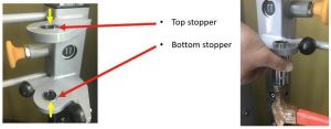
 Install the New Hardware and Adjustable Pulley
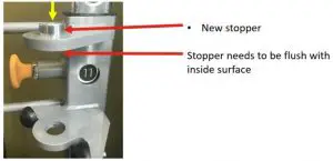
 Note: If the hardware from inside the adjustable pulley falls out clean, grease, then reinstall the hardware in the order shown below. The side shown facing up should be turned over and installed downward into the adjustable pulley.
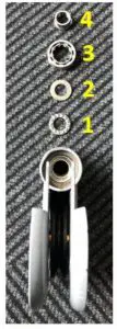
 Tension the Cable Bolt
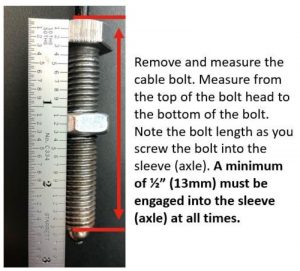
- a. Remove the cable bolt.
- b. Turn it down so that ½” of engagement is achieved.
- c. Tighten the jam nut using an adjustable wrench.
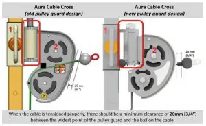
- d. Check the cable ball end measurement. Proper tension should leave 20mm of clearance at the widest point on the pulley guard as shown below.
- e. Adjust the cable bolt down as needed. Always tighten the jam nut with a wrench when you are done.
References
[xyz-ips snippet=”download-snippet”]