
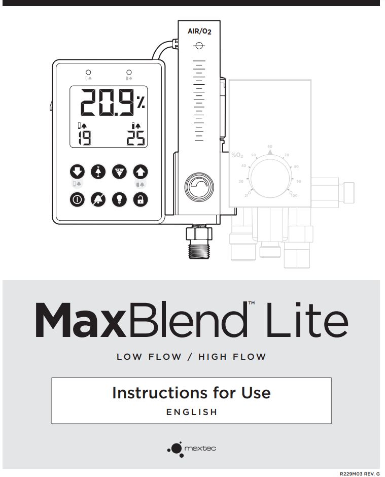
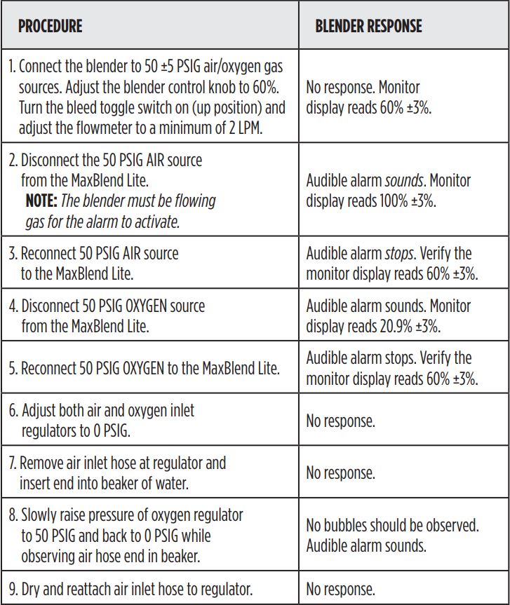
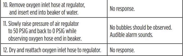
MaxBlend Low Flow High Flow For
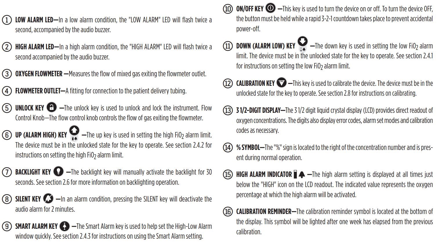
Precision Blender Instructions
![]() Maxtec 2305 South 1070 West Salt Lake City, Utah 84119 USA
Maxtec 2305 South 1070 West Salt Lake City, Utah 84119 USA
phone: (800) 748.5355fax: (801) 973.6090email: [email protected]web: www.maxtec.com
![]() -0123
-0123
![]() Conforms to: AAMI STD ES60601-1, ISO STD 80601-2-55, IEC STDS 606011-6, 60601-1-8 & 62366Certified to: CSA STD C22.2 No. 60601-1
Conforms to: AAMI STD ES60601-1, ISO STD 80601-2-55, IEC STDS 606011-6, 60601-1-8 & 62366Certified to: CSA STD C22.2 No. 60601-1
NOTE: The latest edition of this operating manual can be downloaded from our website at www.maxtec.com
Read this entire manual before attempting to operate or service the MaxBlend Lite. Attempting to operate the MaxBlend Lite without fully understanding its features and functions may result in unsafe operating conditions.
CLASSIFICATION
Protection class: …II, Type BProtection against water:……IPX1Mode of operation:…….ContinuousSterilization: …See section 5.0Safety of application in the presence of a flammable anesthetic mixture: ….See section 9.4Power specification:…….7.5V(MAX) 1.9W/250mA(MAX)
![]() CAUTION: Federal law restricts this device to sale by, or on the order of, a medical professional.
CAUTION: Federal law restricts this device to sale by, or on the order of, a medical professional.
![]() Product Disposal Instructions:The sensor, batteries, and circuit board are not suitable for regular trash disposal. Return sensor to Mixtec for proper disposal or dispose according to local guidelines. Follow local guidelines for disposal of other components. There are no special considerations for the disposal of the product packaging.
Product Disposal Instructions:The sensor, batteries, and circuit board are not suitable for regular trash disposal. Return sensor to Mixtec for proper disposal or dispose according to local guidelines. Follow local guidelines for disposal of other components. There are no special considerations for the disposal of the product packaging.
WARRANTY
The MaxBlend Lite is designed for air/oxygen delivery. Under normal operating conditions, Maxtec warrants the MaxBlend Lite to be free from defects of workmanship or materials for a period of three years from the date of receipt from Maxtec, provided that the unit is properly operated and maintained in accordance with Maxtec’s operating instructions. Based on Maxtec’s product evaluation, Maxtec’s sole obligation under the foregoing warranty is limited to making replacements, repairs, or issuing credit for equipment found to be defective. This warranty extends only to the buyer purchasing the equipment directly from Maxtec or through Maxtec’s designated distributors and agents as new equipment. Maxtec warrants the MAX-550E oxygen sensor in the MaxBlend Lite to be free from defects in material and workmanship for a period of two years from Maxtec’s date of shipment in a MaxBlend Lite unit. Should a sensor fail prematurely, the replacement sensor is warranted for the remainder of the original sensor warranty period. Routine maintenance items, such as batteries, are excluded from warranty. Maxtec and any other subsidiaries shall not be liable to the purchaser or other persons for incidental or consequential damages or equipment that has been subject to abuse, misuse, mies-application, alteration, negligence or accident. THESE WARRANTIES ARE EXCLUSIVE AND IN LIEU OF ALL OTHER WARRANTIES, EXPRESSED OR IMPLIED, INCLUDING WARRANTY OF MERCHANTABILITY AND FITNESS FOR A PARTICULAR PURPOSE.NOTE: In order to obtain optimum performance from your MaxBlend Lite, all operation and maintenance must be performed in accordance with this manual. Please read the manual thoroughly before using the MaxBlend Lite and do not attempt any repair or procedure that is not described herein. Maxtec cannot warranty any damage resulting from misuse, unauthorized repair or improper maintenance of the instrument.
EMC NoticeThis equipment generates, uses, and can radiate radio frequency energy. If not installed and used in accordance with the instructions in this manual, electromagnetic interference may result.The equipment has been tested and found to comply with the limits set forth in IEC 606011-2 for medical products. These limits provide reasonable protection against electromagnetic interference when operated in the intended use environments described in this manual.
![]() MRI NoticeThis equipment contains electronic and ferrous components whose operation can be affected by intense electromagnetic fields. Do not operate the MaxBlend Lite in an MRI environment or in the vicinity of high-frequency surgical diathermy equipment, defibrillators, or shortwave therapy equipment. Electromagnetic interference could disrupt the operation of the MaxBlend Lite.
MRI NoticeThis equipment contains electronic and ferrous components whose operation can be affected by intense electromagnetic fields. Do not operate the MaxBlend Lite in an MRI environment or in the vicinity of high-frequency surgical diathermy equipment, defibrillators, or shortwave therapy equipment. Electromagnetic interference could disrupt the operation of the MaxBlend Lite.
WARNINGS ![]()
Indicates a potentially hazardous situation, if not avoided, could result in death or serious injury.The following warnings apply any time you operate or service the MaxBlend Lite :
◆ Always confirm prescribed flow before administering to patient and monitor flow on a frequent basis.◆ Always follow ANSI and CGA standards for medical gas products, flowmeters, and oxygen handling.
![]() DO NOT operate the MaxBlend Lite unless qualified personnel are in attendance to promptly respond to alarms, inoperative conditions, or sudden malfunctions. Patients on life-support equipment should be visually monitored at all times.
DO NOT operate the MaxBlend Lite unless qualified personnel are in attendance to promptly respond to alarms, inoperative conditions, or sudden malfunctions. Patients on life-support equipment should be visually monitored at all times.![]() DO NOT ignore audible alarms of the MaxBlend Lite. Alarms indicate conditions that require your immediate attention.
DO NOT ignore audible alarms of the MaxBlend Lite. Alarms indicate conditions that require your immediate attention.![]() DO NOT use parts, accessories, or options that have not been authorized for use with the MaxBlend Lite. Using unauthorized parts, accessories, or options may be harmful to the patient or damage the MaxBlend Lite.◆ Check all audible and visual alarms periodically to ensure they are operating properly. If an alarm fails to activate, contact your Maxtec Certified Service Technician.
DO NOT use parts, accessories, or options that have not been authorized for use with the MaxBlend Lite. Using unauthorized parts, accessories, or options may be harmful to the patient or damage the MaxBlend Lite.◆ Check all audible and visual alarms periodically to ensure they are operating properly. If an alarm fails to activate, contact your Maxtec Certified Service Technician.![]() DO NOT operate the MaxBlend Lite with the monitor powered off or without setting the adjustable alarms. All adjustable alarms must be set to ensure safe operation.
DO NOT operate the MaxBlend Lite with the monitor powered off or without setting the adjustable alarms. All adjustable alarms must be set to ensure safe operation.![]() DO NOT steam autoclave or otherwise subject the MaxBlend Lite to temperatures above 122°F (50°C).
DO NOT steam autoclave or otherwise subject the MaxBlend Lite to temperatures above 122°F (50°C).![]() DO NOT tape, obstruct or remove the alarm during clinical use.
DO NOT tape, obstruct or remove the alarm during clinical use.![]() DO NOT occlude the sensor port on the side of the MaxBlend Lite.◆ An air inlet/water filter is recommended for use with the MaxBlend Lite. See section 6.1.◆ If the MaxBlend Lite does not function as described in section 2, contact your Maxtec distributor or Maxtec Certified Service Technician.
DO NOT occlude the sensor port on the side of the MaxBlend Lite.◆ An air inlet/water filter is recommended for use with the MaxBlend Lite. See section 6.1.◆ If the MaxBlend Lite does not function as described in section 2, contact your Maxtec distributor or Maxtec Certified Service Technician.![]() DO NOT use the MaxBlend Lite until correct performance has been verified. See section 3.0.◆ If a condition is detected that could possibly prevent the monitor from continuing to operate safely, it will sound an alarm. If at any time, EOx (i.e. EO2, EO4, etc.) appears on the LCD, refer to section 4.0 or contact a Maxtec Certified Service Technician.◆ All service should be referred to a Maxtec Certified Service Technician.◆ Maxtec recommends that the MaxBlend Lite be serviced by Maxtec every three years, or if a leak or other performance problem is suspected.◆ If the MaxBlend Lite is dropped, follow the procedures outlined in section 3.0 for a performance check before reusing the device.◆ Always remove the batteries to protect the unit from potential leaky battery damage when the unit is going to be stored (not in use for more than 30 days).◆ Always replace batteries with recognized name brand AA alkaline batteries.◆ The MaxBlend Lite has the ability to set the low oxygen alarm below 18% and can be set as low as 15% (see section 2.3 on setting alarms). This is in accordance with ISO 80601-2-55.
DO NOT use the MaxBlend Lite until correct performance has been verified. See section 3.0.◆ If a condition is detected that could possibly prevent the monitor from continuing to operate safely, it will sound an alarm. If at any time, EOx (i.e. EO2, EO4, etc.) appears on the LCD, refer to section 4.0 or contact a Maxtec Certified Service Technician.◆ All service should be referred to a Maxtec Certified Service Technician.◆ Maxtec recommends that the MaxBlend Lite be serviced by Maxtec every three years, or if a leak or other performance problem is suspected.◆ If the MaxBlend Lite is dropped, follow the procedures outlined in section 3.0 for a performance check before reusing the device.◆ Always remove the batteries to protect the unit from potential leaky battery damage when the unit is going to be stored (not in use for more than 30 days).◆ Always replace batteries with recognized name brand AA alkaline batteries.◆ The MaxBlend Lite has the ability to set the low oxygen alarm below 18% and can be set as low as 15% (see section 2.3 on setting alarms). This is in accordance with ISO 80601-2-55.![]() DO NOT use lubricants on the MaxBlend Lite.To prevent risk of burns, fire or injury to person(s):◆ The sensor bleed continuously bleeds to atmosphere at the oxygen concentration setting ofthe blender control knob. Bleeding oxygen into any closed area could increase the risk of fire or explosion.
DO NOT use lubricants on the MaxBlend Lite.To prevent risk of burns, fire or injury to person(s):◆ The sensor bleed continuously bleeds to atmosphere at the oxygen concentration setting ofthe blender control knob. Bleeding oxygen into any closed area could increase the risk of fire or explosion. ![]() DO NOT operate this device in the presence of any flame or source of ignition; or when using equipment such electrosurgical equipment or defibrillators.◆ To avoid explosion,
DO NOT operate this device in the presence of any flame or source of ignition; or when using equipment such electrosurgical equipment or defibrillators.◆ To avoid explosion, ![]() DO NOT operate the MaxBlend Lite in the presence of flammable anesthetics or in an atmosphere of explosive gases. Operating the MaxBlend Lite in flammable or explosive atmospheres may result in fire or explosion.◆ Galvanic O2 sensor electrolyte gel is acidic and may cause skin or eye irritation and/or burns. Take care when handling or replacing exhausted or damaged disposable O2 sensors. Be sure to dispose of expired sensors in accordance with hospital and/or governmental regulations (O2 Sensor SDS available upon request from Maxtec).
DO NOT operate the MaxBlend Lite in the presence of flammable anesthetics or in an atmosphere of explosive gases. Operating the MaxBlend Lite in flammable or explosive atmospheres may result in fire or explosion.◆ Galvanic O2 sensor electrolyte gel is acidic and may cause skin or eye irritation and/or burns. Take care when handling or replacing exhausted or damaged disposable O2 sensors. Be sure to dispose of expired sensors in accordance with hospital and/or governmental regulations (O2 Sensor SDS available upon request from Maxtec).![]() DO NOT use or store oils, greases, organic lubricants or any combustible materials on or near this device.
DO NOT use or store oils, greases, organic lubricants or any combustible materials on or near this device.![]() DO NOT gas sterilize the MaxBlend Lite
DO NOT gas sterilize the MaxBlend Lite![]() DO NOT smoke in an area where oxygen is being used.
DO NOT smoke in an area where oxygen is being used.![]() CAUTION: Indicates a potentially hazardous situation, if not avoided, could result in minor or moderate injury and property damage.
CAUTION: Indicates a potentially hazardous situation, if not avoided, could result in minor or moderate injury and property damage.![]() DO NOT store the MaxBlend Lite in hot areas for prolonged periods of time. Temperatures above 80°F (27°C) can shorten battery life.To minimize the potential for electrostatic shock, do not use antistatic or electrically conductive hoses with the MaxBlend Lite.
DO NOT store the MaxBlend Lite in hot areas for prolonged periods of time. Temperatures above 80°F (27°C) can shorten battery life.To minimize the potential for electrostatic shock, do not use antistatic or electrically conductive hoses with the MaxBlend Lite.![]() DO NOT clean or dry the MaxBlend Lite with a high pressure air gun. Applying high pressure air to the MaxBlend Lite may damage components and render the system inoperable.
DO NOT clean or dry the MaxBlend Lite with a high pressure air gun. Applying high pressure air to the MaxBlend Lite may damage components and render the system inoperable.![]() DO NOT over clean the MaxBlend Lite. Repeated use of a cleaning agent can cause residue buildup on critical components. Excessive residue buildup can affect the MaxBlend Lute’s performance.◆ When cleaning the MaxBlend Lite:
DO NOT over clean the MaxBlend Lite. Repeated use of a cleaning agent can cause residue buildup on critical components. Excessive residue buildup can affect the MaxBlend Lute’s performance.◆ When cleaning the MaxBlend Lite: ![]() DO NOT use harsh abrasives.
DO NOT use harsh abrasives. ![]() DO NOT immerse the MaxBlend Lite in liquid sterilizing agents or liquids of any kind.
DO NOT immerse the MaxBlend Lite in liquid sterilizing agents or liquids of any kind. ![]() DO NOT spray cleaning solution directly onto the front panel, sensor port, bleed muffler or buzzer opening.
DO NOT spray cleaning solution directly onto the front panel, sensor port, bleed muffler or buzzer opening. ![]() DO NOT allow cleaning solution to pool on the front panel, sensor port or bleed muffler.
DO NOT allow cleaning solution to pool on the front panel, sensor port or bleed muffler.![]() DO NOT sterilize the MaxBlend Lite. Standard sterilization techniques may damage the blender.◆ If the MaxBlend Lite does not function as outlined in section 2.0, contact a Maxtec trained service technician or Maxtec for service.
DO NOT sterilize the MaxBlend Lite. Standard sterilization techniques may damage the blender.◆ If the MaxBlend Lite does not function as outlined in section 2.0, contact a Maxtec trained service technician or Maxtec for service.![]() DO NOT attempt to clean the MaxBlend Lite using agents or methods other than those specified in the cleaning section of this document.◆ Dropping or severely jarring the sensor after calibration may shift the calibration point enough to require recalibration.◆ Always operate the MaxBlend Lite with clean, dry medical grade gases. Contaminants or moisture can cause defective operation. Oxygen should have a minimum dewpoint of -80°F (-62°C) or moisture content less than 7.9 PPM (0.0059mg/L). Oxygen “purity” should be at least 99.0% and air used should be medical grade. Water vapor content must not exceed a dew point of 5°F (-15°C) below the lowest ambient temperature to which the delivery system is exposed. Particulate content must not exceed that which would be found immediately downstream of a 15 micron absolute filter. Refer to CGA commodity specifications G-4.3 and G7.1 for more information. Water vapor content of medical air or O2 supply to the blender must not exceed 5.63 x 10³ milligrams H2O per cubic meter of non-condensable gas.
DO NOT attempt to clean the MaxBlend Lite using agents or methods other than those specified in the cleaning section of this document.◆ Dropping or severely jarring the sensor after calibration may shift the calibration point enough to require recalibration.◆ Always operate the MaxBlend Lite with clean, dry medical grade gases. Contaminants or moisture can cause defective operation. Oxygen should have a minimum dewpoint of -80°F (-62°C) or moisture content less than 7.9 PPM (0.0059mg/L). Oxygen “purity” should be at least 99.0% and air used should be medical grade. Water vapor content must not exceed a dew point of 5°F (-15°C) below the lowest ambient temperature to which the delivery system is exposed. Particulate content must not exceed that which would be found immediately downstream of a 15 micron absolute filter. Refer to CGA commodity specifications G-4.3 and G7.1 for more information. Water vapor content of medical air or O2 supply to the blender must not exceed 5.63 x 10³ milligrams H2O per cubic meter of non-condensable gas.![]() DO NOT disassemble the MaxBlend Lite. All service should be performed by a Maxtec Certified Service Technician.◆ Be sure the MaxBlend Lite is securely mounted. This device is usually mounted to a hospital rail system or an infusion stand. Dropping the device may cause injury or device damage.◆ The oxygen sensors contain a weak acidic solution encapsulated in a plastic housing. Under normal operating conditions the solution (electrolyte) is never exposed.
DO NOT disassemble the MaxBlend Lite. All service should be performed by a Maxtec Certified Service Technician.◆ Be sure the MaxBlend Lite is securely mounted. This device is usually mounted to a hospital rail system or an infusion stand. Dropping the device may cause injury or device damage.◆ The oxygen sensors contain a weak acidic solution encapsulated in a plastic housing. Under normal operating conditions the solution (electrolyte) is never exposed.![]() DO NOT use the oxygen sensor if it appears to be damaged or is leaking.NOTES: Indicates supplemental information to assist in use of the device.◆ Applicable parts used in the MaxBlend Lite have been cleaned and degreased for oxygen service. Any lubricants used are designed specifically for the application.◆ As long as the absolute pressure of the gas mixture being monitored is constant, the MaxBlend Lite will accurately read oxygen concentrations. However, if the absolute pressure varies the reading will fluctuate proportionately as the sensor actually measures the partial pressure of oxygen in the mixture. The sensor readings will also change proportionately with barometric pressure changes. Because of this, daily calibration of the sensor is recommended.◆ Users are advised to use pressure regulators which display the outlet pressure. Inlet pressures should be set according to the oxygen/air blender’s specifications.◆ All specifications assume the following standard environmental conditions, unless specified otherwise. Ambient and sample gas temperatures of 77°F (25°C); barometric pressure of 30inHg (760mmHg); ambient relative humidity of 50%; sample gas relative humidity of 0%.◆ The alarm limits can be set to levels that would render them useless for a particular patient’s clinical condition. Ensure that the delivered oxygen level and flow rate are set to values prescribed by the patient’s physician. Also ensure that the high and low alarm limits are set to levels such that they will sound if the oxygen level is outside of safe limits. Be sure to review and, if necessary, re-set the alarm limits when the patient’s clinical condition changes or when the patient’s physician prescribes a change in oxygen therapy.◆ This device does not contain automatic barometric pressure compensation.◆ Gas leaks that cause room air to mix with the gas sample may cause inaccurate oxygen readings. Ensure the O-rings on the sensor and flow diverter are in place and intact prior to use.
DO NOT use the oxygen sensor if it appears to be damaged or is leaking.NOTES: Indicates supplemental information to assist in use of the device.◆ Applicable parts used in the MaxBlend Lite have been cleaned and degreased for oxygen service. Any lubricants used are designed specifically for the application.◆ As long as the absolute pressure of the gas mixture being monitored is constant, the MaxBlend Lite will accurately read oxygen concentrations. However, if the absolute pressure varies the reading will fluctuate proportionately as the sensor actually measures the partial pressure of oxygen in the mixture. The sensor readings will also change proportionately with barometric pressure changes. Because of this, daily calibration of the sensor is recommended.◆ Users are advised to use pressure regulators which display the outlet pressure. Inlet pressures should be set according to the oxygen/air blender’s specifications.◆ All specifications assume the following standard environmental conditions, unless specified otherwise. Ambient and sample gas temperatures of 77°F (25°C); barometric pressure of 30inHg (760mmHg); ambient relative humidity of 50%; sample gas relative humidity of 0%.◆ The alarm limits can be set to levels that would render them useless for a particular patient’s clinical condition. Ensure that the delivered oxygen level and flow rate are set to values prescribed by the patient’s physician. Also ensure that the high and low alarm limits are set to levels such that they will sound if the oxygen level is outside of safe limits. Be sure to review and, if necessary, re-set the alarm limits when the patient’s clinical condition changes or when the patient’s physician prescribes a change in oxygen therapy.◆ This device does not contain automatic barometric pressure compensation.◆ Gas leaks that cause room air to mix with the gas sample may cause inaccurate oxygen readings. Ensure the O-rings on the sensor and flow diverter are in place and intact prior to use.
1.0 INTRODUCTION
The MaxBlend Lite is an accessory to an air/oxygen blender, which incorporates the use of a battery powered oxygen monitor and flowmeter. A blender provides precise mixing of medical grade air and oxygen, while the monitor measures the oxygen concentrations from the blender’s outlet and displays these measured concentrations on a digital display. The monitor also provides adjustable high and low alarm limits which, when exceeded, activate an audible and visual alarm. An integrated flowmeter enables precise flow control of the delivered gas mixture.
1.1 Indication for Use
The MaxBlend Lite is designed to provide a continuous air/oxygen gas mixture and to continuously monitor the concentration of oxygen being delivered to infant, pediatric, and adult patients. It is a restricted medical device intended for use by qualified, trained personnel, under the direction of a physician, in professional healthcare settings, i.e., hospital, subacute, and nursing-care facilities where the delivery and monitoring of air/oxygen mixtures is required. This is not intended as a life supporting device.
1.2 MAX-550E Oxygen Sensor
The MAX-550E is a galvanic, partial pressure sensor that is specific to oxygen. It consists of two electrodes (a cathode and an anode), a Teflon membrane and an electrolyte. Oxygen diffuses through the Teflon membrane and immediately reacts electrochemically at a gold cathode. Concurrently, oxidation occurs electrochemically at a lead anode, generating an electrical current and providing a voltage output. Electrodes are immersed in a unique gelled weak acid electrolyte which is responsible for the sensors long life and motion insensitive characteristic. Since the sensor is specific to oxygen, the current generated is proportional to the amount of oxygen present in the sample gas. When no oxygen is present, there is no electrochemical reaction and therefore, negligible current is produced. In this sense, the sensor is self-zeroing.
![]() CAUTION: The MAX-550E oxygen sensor is a sealed device containing a mild acid electrolyte and lead (Pb). These materials are hazardous waste constituents and should be disposed of properly, or returned to Maxtec for proper disposal or recovery.
CAUTION: The MAX-550E oxygen sensor is a sealed device containing a mild acid electrolyte and lead (Pb). These materials are hazardous waste constituents and should be disposed of properly, or returned to Maxtec for proper disposal or recovery.![]() CAUTION: Dropping or severely jarring the sensor after calibration may shift the calibration point enough to require re-calibration.
CAUTION: Dropping or severely jarring the sensor after calibration may shift the calibration point enough to require re-calibration.
1.3 Symbol Guide
The following symbols and safety labels are found on the MaxBlend Lite and/or labeling:
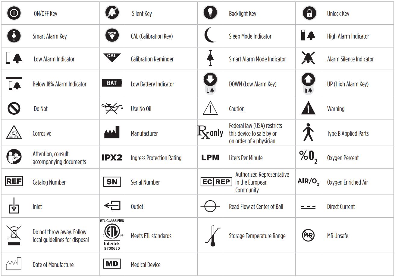
POWER SUPPLY SYMBOL GUIDEThe following symbols and safety labels are found on the MaxBlend 2 power supply (sold separately):

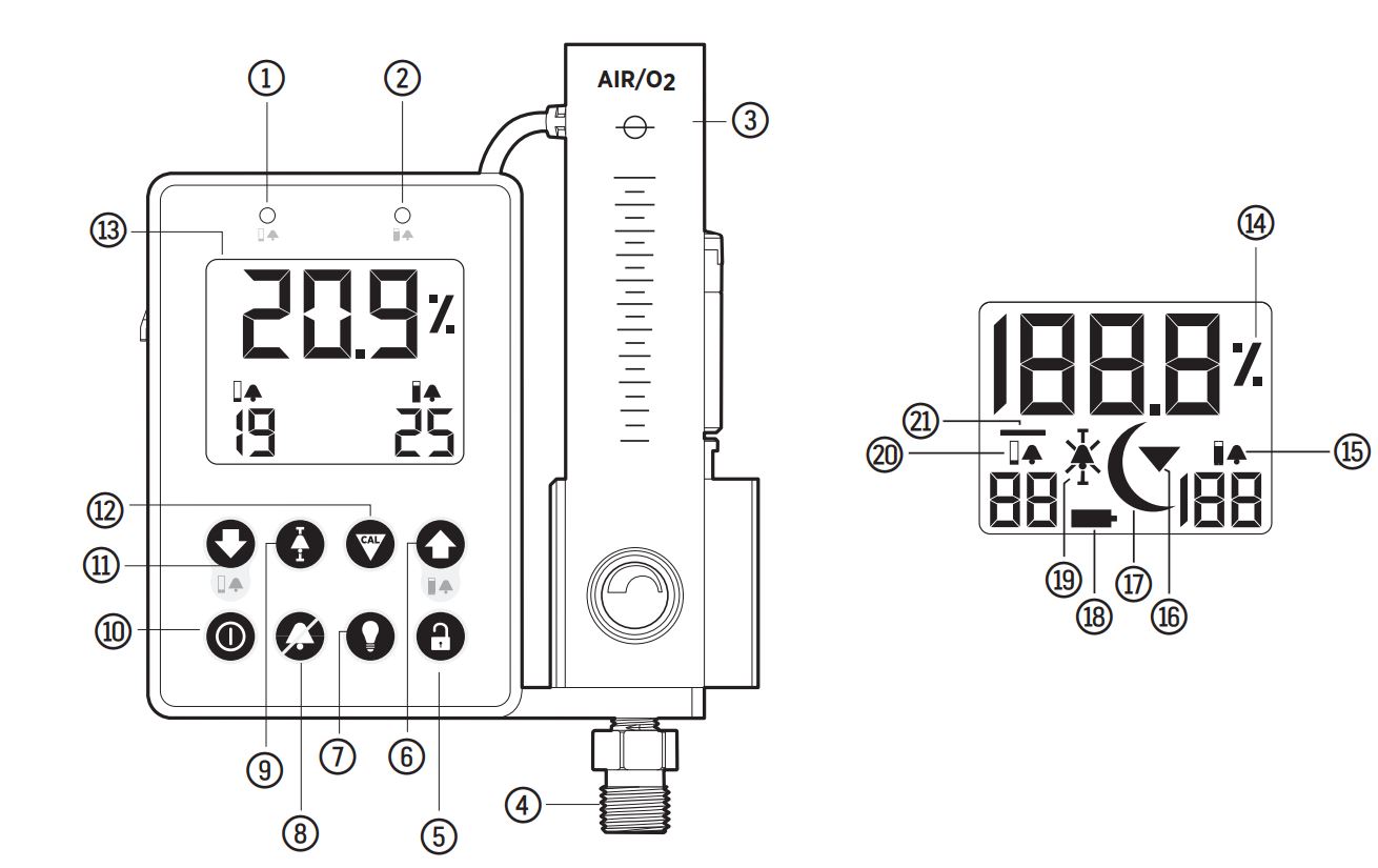
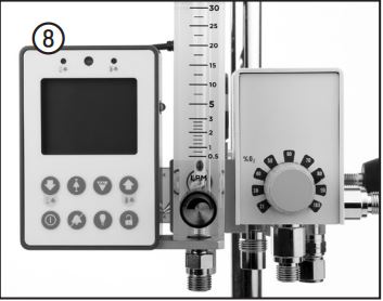
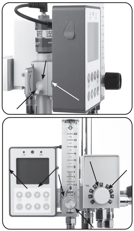
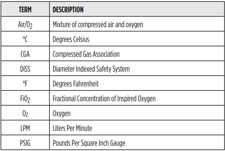
1.4Component Identification
 1.5 Side Views
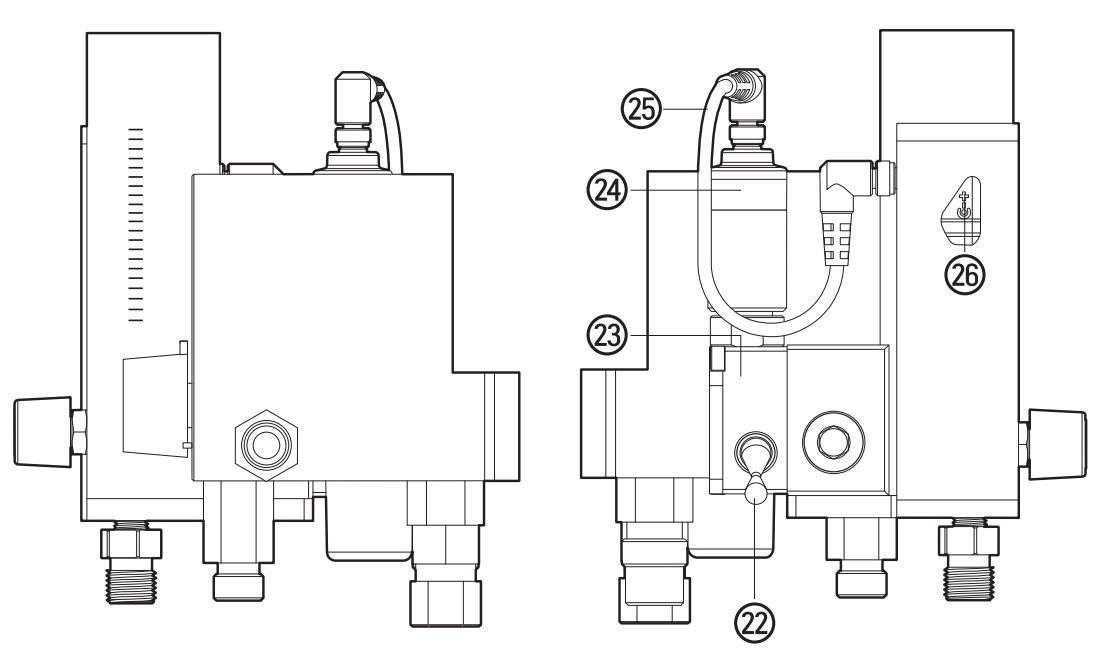
 1.5 Side Views
1.6 Essential Device Performance
Essential performance are the operating characteristics of the device, without which would result in an unacceptable risk. The following items are considered essential performance:
- Oxygen measurement accuracy
- Operation of visible and audible alarms
- Operation of blender bypass
- Operation of reverse gas flow protection
1.7 What You Will Need to Operate the Blender
All operator-detachable inlet pressure hoses supplied with the gas mixer.Pressurized Oxygen: The compressed oxygen source must provide clean, dry, medical grade oxygen at the pressure specified in the air/oxygen blender’s instructions for use. This pressure is typically 30 to 75 PSIG (2.0 to 5.2 BAR).Pressurized Air: The compressed air source must provide clean, dry, medical grade air at the pressure specified in the air-oxygen blender’s instructions for use. This pressure is typically 30 to 75 PSIG (2.0 to 5.2 BAR).
2.0 OPERATING PROCEDURES
2.1 Setup and Installation
2.1.1 MaxBlend Lite Compatibility:
This section details the characteristics required of oxygen/air blenders to be compatible with the MaxBlend Lite. All medical oxygen air blenders have similar performance requirements in order to comply with international standards (ISO11195 Gas mixers for medical use–Standalone gas mixers). However, the physical shape of the blender varies from model to model. The following requirements detail the blender requirements necessary for compatibility with the MaxBlend Lite. If you are unsure if your blender meets these requirements, please contact Maxtec’s service department for assistance.
Blender compatibility requirements:
- The blender must comply with ISO11195.
- For optimal flowmeter accuracy, the blender must be capable of operating with inlet pressures set to 50 psi (3.45 bar).
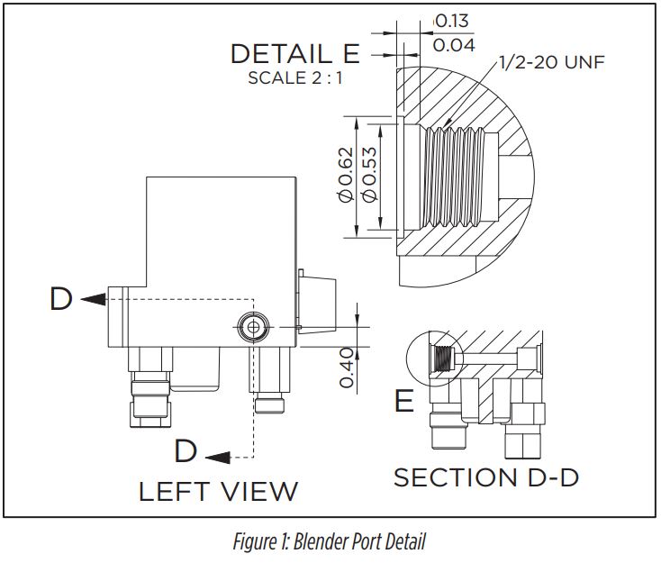
- The blender must have a primary outlet port on the left hand side of the blender with dimensions as shown in Figure 1.
2.1.2 Sensor Installation
- Attach the flow diverter onto the oxygen sensor.
- Place the sensor into the sensor port located behind the flowmeter.
- Attach the sensor cable directly to the sensor and the sensor jack on the back of the monitor enclosure. Ensure the cable is fully inserted into both connections.
- Calibrate the sensor prior to use according to the calibration procedures in section 2.8
2.1.3 Battery Installation
All MaxBlend Lite units are powered by four, AA, alkaline batteries (4 x 1.5 Volts) and are shipped without the batteries installed. The battery compartment is accessible from the back side of the unit. Batteries should be changed by service personnel. Use only brand name batteries. Replace with four AA batteries and insert per orientation marked inside the battery box.
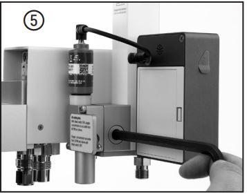
To install the batteries:Open the battery door by pressing down on the door latch as shown in the figure below. Remove the battery door completely from the MaxBlend Lite. Install four new, AA, alkaline batteries in the unit, observing the orientation shown on the plastic behind the batteries. Slide the door back in place in the reverse order that it was removed. Press in on the door until it latches into place.
![]() WARNING: Battery replacement by inadequately trained personnel could result in a safety hazard.
WARNING: Battery replacement by inadequately trained personnel could result in a safety hazard.
![]() WARNING: Electrical shock or damage to the equipment may occur if an inappropriate external power supply is used. Maxtec recommends using only the Maxtec MaxBlend Lite External Power Supply – R230P10.
WARNING: Electrical shock or damage to the equipment may occur if an inappropriate external power supply is used. Maxtec recommends using only the Maxtec MaxBlend Lite External Power Supply – R230P10.

2.1.4 MaxBlend Lite Installation
The MaxBlend Lite must be installed correctly in order to function properly. If you have any difficulty installing the MaxBlend Lite, or if you are unsure about the installation process or blender compatibility please contact Maxtec’s service department before attempting installation.
NOTE: For Micro Max or Precision Medical blenders an inlet adapter is required. Install the inlet adapter kit (included with the following REF R229P03-005, -006, -007 and -008) prior to installing the MaxBlend Lite. After installing the adapter, proceed to installation step 3.
![]() WARNING: Prior to installing the MaxBlend Lite, ensure that the oxygen/air blender is compatible.
WARNING: Prior to installing the MaxBlend Lite, ensure that the oxygen/air blender is compatible.
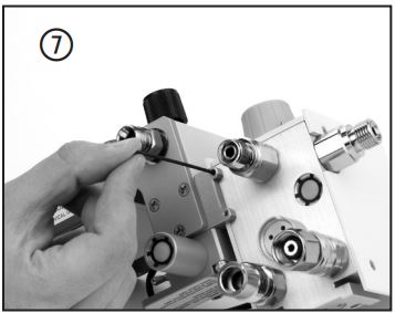
- Disconnect gas supplies from the blender. Remove the port fitting from the left hand side of the blender. Be sure to remove the spring and O-ring from the port.
- Thoroughly clean the port including the threads to remove any visible contaminants.
- Check to make sure the O-ring is present on the threaded bolt of the MaxBlend Lite.
- Line-up the threaded bolt of the MaxBlend Lite with the port on the left side of the blender.
- Insert the long end of a 5/16″ hex key into the hex shaped hole behind the MaxBlend Lite.
- Ensure the MaxBlend Lite is aligned parallel with the side of the blender and ensure the step on the bottom edge of the MaxBlend Lite is oriented so it will fit under the edge of the blender as you connect them together. It is critical that the blender and the MaxBlend Lite be aligned properly to prevent the fastener from cross-threading and damaging the blender. Slowly turn the hex key in a clockwise direction to thread the fastener into the blender. Firmly tighten until the shoulder is flush with the blender.
- Using a 1/16″ hex key, thread the set screws in until they lightly contact the bottom of the blender. Adjust as necessary to orient the flow meter to be parallel with the blender.
- Connect the pressurized air source to the air inlet fitting of the blender.
- Connect the pressurized oxygen source to the oxygen fitting of the blender.
- Before placing into service, check for leaks using an oxygen safe leak detector.
- Flow gas through the MaxBlend Lite at the maximum flow for at least 1 minute to flush out any particulates that may have been introduced during handling and installation. Refer to the instructions for use of the oxygen/air blender to carry out the performance verification tests outline therein prior to use on a patient.
 Ensure the MaxBlend Lite is aligned parallel with the side of the blender and ensure the step on the bottom edge of the MaxBlend Lite is oriented so it will fit under the edge of the blender as you connect them together. It is critical that the blender and the MaxBlend Lite be aligned properly to prevent the fastener from cross-threading and damaging the blender. Slowly turn the hex key in a clockwise direction to thread the fastener into the blender. Firmly tighten until the shoulder is flush with the blender.
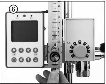
![]() CAUTION: Installation should only be performed by adequately trained personnel.
CAUTION: Installation should only be performed by adequately trained personnel.
2.2 Monitoring
Before use on a patient, the oxygen concentration of the delivered gas should be checked at the setting intended for use.
To begin monitoring, press the ON/OFF key ![]() Monitoring will begin immediately.
Monitoring will begin immediately.
Should oxygen level exceed either the HIGH or LOW alarm set points, the alarm indicator on the front panel will illuminate indicating either a high or low oxygen condition within limits or the limits are adjusted.
NOTE: The MaxBlend Lite will monitor the oxygen concentration of the gas delivered from the blender regardless of which outlet port is in use. Therefore, the integrated flowmeter has ultimately no effect on the oxygen sensing.
2.3 Flowmeter Operation
- Adjust the flowmeter to the desired setpoint as read by the center of the float ball.• To increase flow – turn knob counter-clockwise• To decrease flow – turn knob clockwise
- Check the toggle bleed switch to ensure it is in the appropriate position.• For a low flow blender the bleed toggle switch should be turned on (up position) if the total combined flow from the blender is less than 3LPM.• For a high flow blender the bleed toggle switch should be turned on (up position) if the total combined flow from the blender is less than 15LPM.• At delivered flows greater than the above limits, the bleed toggle switch can be turned off (down position) to conserve gas.
![]() CAUTION: Failure to activate the bleed as described above may result in inaccurate oxygen concentrations from the blender. However, the MaxBlend Lite will always display the actual delivered concentration.
CAUTION: Failure to activate the bleed as described above may result in inaccurate oxygen concentrations from the blender. However, the MaxBlend Lite will always display the actual delivered concentration.
![]() CAUTION: The outlets of this device are capable of delivering pressure as high as the inlet pressure. Ensure that the devices that carry the gas from the blender to the patient prevent excessive pressure to the patient.
CAUTION: The outlets of this device are capable of delivering pressure as high as the inlet pressure. Ensure that the devices that carry the gas from the blender to the patient prevent excessive pressure to the patient.
2.4 Alarm Setting Procedure
2.4.1 Low Alarm Setting
To adjust the low alarm setting:
- Press the Unlock key to unlock the keypad. Note the LOW, Smart Alarm, CAL and HIGH icons will begin to flash indicating the SET OPERATING MODE.
- Press the DOWN (LOW ALARM) key on the keypad.NOTE: the Low Alarm digits begin to flash indicating the Low Alarm manual setting.
- Use the UP and DOWN keys to set the low alarm to the desired value. Pressing the arrow keys changes the value in 1% increments. If the keys are held down for more than 1 second the display will scroll at a rate of 1% per second.
NOTE: If 30 seconds elapse between key actuations, the system will store the latest high alarm setting and will revert to normal operation. If this occurs inadvertently, simply repeat the alarm setting procedure.There is a special condition that allows the low oxygen alarm to be set below 18%. To access this condition press the DOWN![]() arrow key for three seconds while the low alarm reading displays 18%. The alarm setting can now be adjusted to 17, 16, or 15%. A bar will blink above the setting to provide further indication that the alarm has been set to this special <18% condition.The low alarm value cannot be set lower than 15%, nor can it be set closer than 1% from the high alarm value. For example, if the high alarm is set at 25%, the system will not accept a low alarm setting greater than 24%.
arrow key for three seconds while the low alarm reading displays 18%. The alarm setting can now be adjusted to 17, 16, or 15%. A bar will blink above the setting to provide further indication that the alarm has been set to this special <18% condition.The low alarm value cannot be set lower than 15%, nor can it be set closer than 1% from the high alarm value. For example, if the high alarm is set at 25%, the system will not accept a low alarm setting greater than 24%.
4. When the low alarm value is set, press the Unlock![]() key to accept the low alarm setting and return to normal operation.NOTE: The default low alarm setting is 18% O2. Removing the batteries or shutting the unit OFF will reset the low alarm limit to 18% if it is set to <18%.
key to accept the low alarm setting and return to normal operation.NOTE: The default low alarm setting is 18% O2. Removing the batteries or shutting the unit OFF will reset the low alarm limit to 18% if it is set to <18%.
2.4.2 High Alarm Setting
To adjust the high alarm setting:
- Press the Unlock key to unlock the keypad. Note the LOW, SMART ALARM, CAL and HIGH icons will begin to flash indicating the SET OPERATING MODE.
- Press the UP (HIGH ALARM) key on the key pad.NOTE: The High Alarm digits begin to flash indicating the High Alarm manual setting.
- Use the UP and DOWN keys to set the high alarm to the desired value. Pressing the arrow keys changes the value in 1% increments. If the keys are held down for more than 1 second the display will scroll at a rate of 1% per second.
NOTE: If 30 seconds elapse between key actuations, the system will store the latest high alarm setting and will revert to normal operation. If this occurs inadvertently, simply repeat the alarm setting procedure. When the high alarm setting is set above 100% the high alarm will indicate two dashes This special condition turns off or deactivates the high alarm.4. When the high alarm value is set, press the Unlock ![]() key again to accept the high alarm setting and return to normal operation.
key again to accept the high alarm setting and return to normal operation.
NOTE: The default high alarm setting is 50% O2. Removing the batteries will reset the high alarm limit to 50%.
2.4.3 Smart Alarm Mode
- Press the Unlock key to Unlock the keypad. Note the LOW, Smart Alarm, CAL and HIGH icons will begin to flash indicating the SET OPERATING MODE.
- Press the Smart Alarm key on the keypad. Note the LOW digits, Alarm Mode and HIGH digits begin a slow flash indicating SMART ALARM MODE. The high alarm will now be set equal to the current oxygen reading +3% (rounded to the nearest integer). The low alarm will now be set equal to the current oxygen reading -3% (rounded to the nearest integer but never lower than 18%).
- Pressing the Up key will add one to the high alarm setting and subtract one from the low alarm setting. Pressing the Down key will subtract one from the high alarm setting and add one to the low alarm setting. In other words, the Up Arrow widens the alarm band and the down arrow tightens the alarm band. This feature will not set the alarm levels above 100% or below 18%.
- Once the desired alarm settings are attained, press the Unlock key to save the settings and return to normal operation mode. If 30 seconds elapse without a key press by the user, the device will automatically save the new alarm settings and return to normal operation mode.
2.5 Alarm Conditions and Priorities
In the event of either a low alarm or high alarm condition, the corresponding LED will begin to flash, accompanied by the audio buzzer. Pressing the SILENT key![]() will deactivate the buzzer but the LED and the alarm value digits on the display will continue to flash until the alarm condition has been rectified. If the alarm condition still exists 120 seconds after silencing the audio buzzer, the beeper will start to sound again.
will deactivate the buzzer but the LED and the alarm value digits on the display will continue to flash until the alarm condition has been rectified. If the alarm condition still exists 120 seconds after silencing the audio buzzer, the beeper will start to sound again.
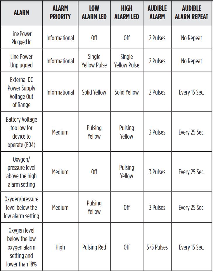
A low alarm condition will remain until the actual concentration is 0.1% higher than the low alarm setting. A high alarm condition will remain until the actual concentration is 0.1% lower than the high alarm setting. To help differentiate the level of severity, the monitor provides three unique sound bursts.
2.6 Backlight Operation
To turn on the backlighting:
- When the unit is on, pressing the Backlight key will turn the backlighting on for 30 seconds. Additional presses will turn off the backlighting.
- If the device is being used in a dark location, press any key to activate the back light.
![]() CAUTION: Excessive use of the backlight can reduce the life of the batteries.
CAUTION: Excessive use of the backlight can reduce the life of the batteries.
2.7 External Power Supply Operation
To extend the life of the batteries an external Maxtec approved external power supply can be purchased. Once connected to the unit, total power is supplied by the power supply. The batteries are still required to be in the unit and will provide emergency power in the event main AC power is lost.
NOTE: Use only the Maxtec external power supply called out in section 10.0.NOTE: The power supply is not a battery charger. ![]() DO NOT use rechargeable batteries.
DO NOT use rechargeable batteries.
2.8 Calibration Procedures
2.8.1 Calibration to 100% Oxygen
The MaxBlend Lite should be calibrated before being placed into clinical use. Thereafter, Maxtec recommends calibration of the unit on a weekly basis. Frequent calibration will have no adverse effect on the performance of the MaxBlend Lite.Calibration should also be performed upon replacement of a sensor. The sensor is best calibrated while mounted in the MaxBlend Lite sensor port. As in normal operation, the oxygen sensor responds best when installed in a vertical position with the sensor facing down.Changes in barometric pressure can affect the oxygen reading. A 1% change in the barometric pressure results in an error of 1% of actual reading (Example: If you are reading a 50% oxygen mix and the barometric pressure drops from 1000mbar to 990mbar the reading will drop to 50% x (990/1000) = 49.5%). Maxtec recommends that you re-calibrate after changing point of-use elevation by more than 500 feet (150m).It is best to calibrate the MaxBlend Lite using the sensor port, and with a technical grade oxygen standard (99.0% or better). Calibration of the unit with room air is less accurate over the full FiO2 operating range.
- Connect the oxygen supply line (Pressure differential alarm may sound). Verify the sensor is plugged into the O2 sensor port and connected to the sensor cable. DO NOT connect air supply line at this time.
- Using the ON/OFF key , make sure the MaxBlend Lite is in the power on mode.
- Rotate the FiO2 control knob to the 100% stop. Allow a few minutes for the reading to stabilize.
- Press the Unlock key to unlock the keypad. Note the LOW, Smart Alarm, CAL and HIGH icons will begin to flash indicating the SET OPERATING MODE.
- Press the CALIBRATION key on the keypad. The word “CAL” will appear on the display for approximately 5 second and then finish with 100.0%. 6. The unit is now calibrated and in the normal operating mode.
2.8.2 Calibration to Room Air
The MaxBlend Lite can quickly be calibrated to room air (20.9%).To use this function:
- Connect the air supply line (Pressure differential alarm may sound). Verify the sensor is plugged into the O2 sensor port and connected to the sensor cable. DO NOT connect oxygen supply line at this time. (If preferred, room-air calibration may be performed by removing the sensor from the O2 sampling port and detaching the flow diverter. If using this method, the gas-supply lines may remain attached.)
- Using the ON/OFF key , make sure the MaxBlend Lite is in the power on mode.
- Rotate the FiO2 control knob to the 21% stop. Allow a few minutes for the reading to stabilize.
- Press the Unlock key to unlock the keypad. Note the LOW, SMART ALARM, CAL and HIGH icons will begin to flash indicating the SET OPERATING MODE.
- Press the CALIBRATION key on the keypad. The word “CAL” will appear on the display for approximately 5 seconds and then finish with 20.9%.
- The unit is now calibrated and in the normal operating mode.
3.0 PERFORMANCE CHECK
Prior to placing the MaxBlend Lite into clinical use, perform the following tests.
![]() WARNING: If the MaxBlend Lite does not function as described, contact your Maxtec Distributor or contact a Maxtec Certified Service Technician at:Maxtec 2305 South 1070 West Salt Lake City, UT 84119 (385) 549-8000 or (800) 748-5355
WARNING: If the MaxBlend Lite does not function as described, contact your Maxtec Distributor or contact a Maxtec Certified Service Technician at:Maxtec 2305 South 1070 West Salt Lake City, UT 84119 (385) 549-8000 or (800) 748-5355
![]() DO NOT use the MaxBlend Lite until correct performance has been verified.
DO NOT use the MaxBlend Lite until correct performance has been verified.
3.1 Blender Safety Check
NOTE: Before proceeding, ensure that the high alarm set point control is OFF [display reads (–)] and that the low alarm set point control is below 20%.
The following performance check is a general recommended test based on typical air/oxygen blenders which may be attached to the MaxBlend Lite. Refer to the instructions for use of the particular blender attached to the MaxBlend Lite for specific blender instructions.
3.2 Monitor Alarm Testing
Testing of monitor alarms should be performed on a yearly basis. To check the low alarm, adjust the low alarm setting to 23% or higher and expose the sensor to room air (20.9%). The low alarm LED should flash with the alarm sound.To check the high alarm, adjust the low alarm setting to 17% or lower and the high alarm setting to 18% and expose the sensor to room air (20.9%). The high alarm LED should flash with the alarm sound. Refer to section 2.5 Alarm Conditions and Priorities. If one or both alarms malfunction, contact Maxtec Certified Service Technician.
4.0 TROUBLESHOOTING
PROBLEM: Oxygen concentration discrepancy between oxygen concentration selection knob and actual reading on display, greater than 3%.Potential Causes and Solutions:
- Bleed is turned off. Turn bleed toggle switch on. Refer to section 2.3, Flowmeter Operation.
- Monitor out of calibration. Calibrate. Refer to section 2.8, Calibration Procedure.
- Sensor exhausted. Replace sensor. Refer to section 6.2.
- Gas supply contaminated. Contact Maxtec for repair of the MaxBlend Lite.
- Blender out of calibration. Contact Maxtec for repair.
PROBLEM: Blank display.Potential Causes and Solutions:
- Battery not installed. Install batteries. Refer to section 2.1.3.
- Battery completely dead. Replace batteries. Refer to section 2.1.3.
- Monitor defective. Contact Maxtec for repair.
PROBLEM: Partial or distorted display.Potential Causes and Solutions:
- Monitor damaged. Contact Maxtec for repair.
PROBLEM: Sensor will not calibrate.
Potential Causes and Solutions:
- Sensor cell exhausted. Replace sensor. Refer to section 6.2.
- Sensor cable defective. Return to Maxtec.
- Monitor defective. Contact Maxtec for repair.
PROBLEM: Sensor will calibrate, but takes too long to return to 21% ±2% oxygen in air (2 to 5 minutes) when performing calibration.
Potential Causes and Solutions:
- Disposable oxygen sensor damaged or defective. Replace sensor. Refer to section 6.2.
PROBLEM: Sensor will calibrate, but does not return to 21% ±2% oxygen in air (2 to 5 minutes) when performing calibration.
Potential Causes and Solutions:
- Disposable oxygen sensor damaged or defective. Replace sensor. Refer to section 6.2.
PROBLEM: Sensor will calibrate, but reading at any constant level drifts more than ±3% over a 24 hour period.
Potential Causes and Solutions:
- Barometric pressure change since last calibration. Recalibrate.
- Room or gas temperature went below 59°F (15°C) or above 104°F (40°C). Correct temperature and recalibrate.
PROBLEM: Low Battery Icon.Potential Causes and Solutions:
- If the low battery icon is displayed on the LCD readout at any time, the batteries should be replaced as quickly as possible.
PROBLEM: E01: Sensor voltage is too low to perform a valid calibration.
Potential Causes and Solutions:
- Manually attempt a new calibration.
- If unit repeats this error more than three times, contact Maxtec’s Customer Service Department for possible sensor replacement.
PROBLEM: E02: No sensor attached.Potential Causes and Solutions:
- Disconnect the sensor and reconnect, making sure the male plug is fully inserted into the receptacle. The analyzer should now perform a new calibration with the error cleared.
- If the error still persists, remove the batteries, wait 30 seconds, then reinstall, to perform a factory reset and diagnostic on the analyzer. The analyzer should again perform a new calibration with the error cleared.
- Contact Maxtec Customer Service Department if the error code cannot be cleared.
PROBLEM: E03: No valid calibration data available.Potential Causes and Solutions:
- Make sure unit has reached thermal equilibrium and perform a calibration routine.
PROBLEM: E04: Battery below minimum operating voltage.Potential Causes and Solutions:
- Replace batteries. A medium priority alarm will sound every 25 seconds until the batteries are replaced or become too dead to sound the alarm.
PROBLEM: E05: Sensor voltage is too high to perform a valid calibration.Potential Causes and Solutions:
- Manually attempt a new calibration.
- If unit repeats this error more than three times, contact Maxtec’s Customer Service Department for possible sensor replacement.
PROBLEM: E06: Non-compatible oxygen sensor.Potential Causes and Solutions:
- Disconnect the sensor and reconnect, making sure the male plug is fully inserted into the receptacle. The analyzer should now perform a new calibration with the error cleared.
- If the error still persists, remove the batteries, wait 30 seconds, then reinstall, to perform a factory reset and diagnostic on the analyzer. The analyzer should again perform a new calibration with the error cleared.
- Contact Maxtec Customer Service Department if the error code cannot be cleared.
PROBLEM: E07: Sensor signal is not stable enough to perform a valid calibration.Potential Causes and Solutions:
- Wait for displayed oxygen reading to stabilize, when calibrating the device at 100% oxygen.
- Wait for unit to reach thermal equilibrium. Please note that this can take up to one half hour, if the device is stored in temperatures outside the specified operating temperature range.
PROBLEM: E08: Battery voltage is too low to perform a valid calibration.Potential Causes and Solutions:
- Replace batteries.
NOTE: Use only a Maxtec approved Max-550E sensor called out in section 10.0 of the Spare Parts List. The Max-550E sensor is equipped with an authentication chip to ensure the monitor is used with an approved sensor.NOTE: The operator must be facing the device and positioned within 4 meters to distinguish the visual alarm indicators. Audible alarms can be distinguished as long as the operator is in the same room and the ambient noise level is typical for a clinical setting.
5.0 CLEANING AND DISINFECTING THE MAXBLEND LITE
The external surfaces of the device and its accessories can be cleaned and disinfected using the process detailed below. Under normal use conditions, the sensing surfaces of the sensor should not become contaminated. If you suspect that the sensing face of the sensor or internal surfaces of the flow diverter have become contaminated, these items should be discarded and replaced. Store the device in a clean, dry location when not in use.
- Ensure battery drawer is closed and sensor/diverter are inserted into their port.
- Using Super Sani-Cloth germicidal disposable wipes (medical grade 2-in- 1 cleaning / disinfecting wipes) remove all visible contamination from the external surfaces of the device and its accessories. Be sure to closely inspect and remove contamination from seams and recesses on the device that may trap contaminants. Wipe with clean paper towel to remove debris and bioburden.
- After all visible contamination is removed, use a second germicidal wipe to thoroughly wet the surfaces of the device and accessories. Allow to remain wet for 4 minutes. Use additional wipes if needed to assure surfaces are wetted continuously for 4 minutes.
- Allow device to air dry completely.
- Visually inspect the device for visible contamination. Repeat cleaning/disinfection process if visible soil remains.
![]() DO NOT allow liquid or spray to penetrate the device.
DO NOT allow liquid or spray to penetrate the device.![]() DO NOT spray cleaning solution directly onto the sensor port, bleed muffler or buzzer openings.Be sure to thoroughly clean and disinfect the areas depicted in the images below. These regions are contacted during normal use and may contribute to cross contamination if not disinfected properly.
DO NOT spray cleaning solution directly onto the sensor port, bleed muffler or buzzer openings.Be sure to thoroughly clean and disinfect the areas depicted in the images below. These regions are contacted during normal use and may contribute to cross contamination if not disinfected properly.![]() CAUTION: Excessive rubbing of labels may cause them to become illegible.
CAUTION: Excessive rubbing of labels may cause them to become illegible.![]() DO NOT immerse the device or sensor into liquid decontamination agents.
DO NOT immerse the device or sensor into liquid decontamination agents.![]() DO NOT use strong solvent cleaners.
DO NOT use strong solvent cleaners.![]() DO NOT allow cleaning liquids to contact the face of the sensor as this may impair the readings of the sensor.
DO NOT allow cleaning liquids to contact the face of the sensor as this may impair the readings of the sensor.![]() DO NOT Attempt to sterilize the device with steam, ethylene oxide or irradiation.
DO NOT Attempt to sterilize the device with steam, ethylene oxide or irradiation.
6.0 SERVICE AND MAINTENANCE
 6.0 SERVICE AND MAINTENANCE
6.1Maintenance
Prior to placing the MaxBlend Lite into clinical use, follow the performance check guidelines listed in section 3 of this manual and any directions indicated in the instructions for use of the oxygen/air blender to which the MaxBlend Lite is attached.When using the MaxBlend Lite with a medical grade compressed air source, an air inlet waterdrop/filter is recommended to be attached to the air inlet of the air/oxygen blender prior to use. Contaminants from hospital air lines may compromise the function of the MaxBlend Lite.Maxtec recommends that the MaxBlend Lite be overhauled and serviced at a minimum of every three years. Refer to the user manual for the oxygen/air blender for any service instruction pertaining thereto.Repair of this equipment must be preformed by a Maxtec Certified Service Technician experienced in repair of this device.
6.2 Replacing O2 Sensor
The oxygen sensor is designed to operate for two years under normal use conditions. The oxygen sensor should be replaced whenever any of the problems listed in section, 4.0 Troubleshooting dictate the need to do so.1. Remove the sensor from the sensor monitor port. 2. Remove the sensor from the sensor cable. 3. Install a new O2 sensor with flow diverter and attach to the sensor cable. 4. Calibrate the sensor following the instructions for calibration listed in section 2.8.
7.0 ABBREVIATION GUIDE
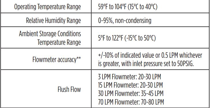
8.0 SPECIFICATIONS
8.1 Instrument Specifications
NOTE: Refer to the instructions for use of the particular blender in use for the specific blender performance requirements.
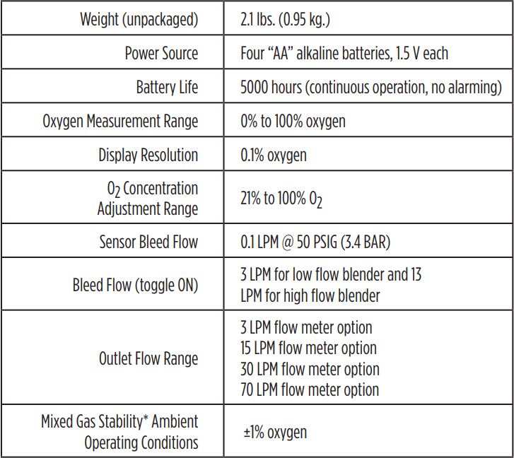
*The delivered oxygen concentration will remain constant within ±1% of the set point value with constant inlet pressures. The displayed value may vary more than this due to sensor accuracy, age, environmental conditions and length of time since last sensor calibration.
**Position the device such that the flow meters are vertical to ensure accuracy.
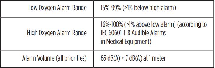
8.2 Alarm Specifications
8.3 O₂ Sensor Specifications
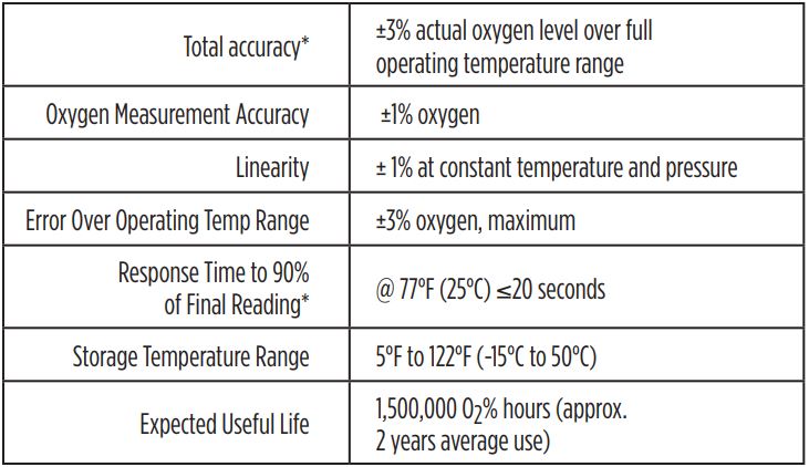
*The accuracy of the oxygen monitor is not affected by supply gas inlet pressure to the blender, however, pressures below 50 PSIG may result in a longer response time.
NOTE: All specifications assume the following standard environmental conditions unless specified otherwise.
- Ambient and sample gas temperatures of 77°F (25°C)
- Barometric pressure of 30 inHg (102 kPa)
- Ambient relative humidity of 50%
- Sample gas relative humidity of 0%
9.0 FACTORS INFLUENCING CALIBRATION
9.1 Temperature Effect
The MaxBlend Lite monitor will hold calibration and read correctly within +/-3% when in thermal equilibrium within the operating temperature range.The device accuracy will be better than +/-3% if operated at the same temperature at which it was calibrated. The device must be thermally stable when calibrated and allowed to thermally stabilize after experiencing temperature changes before reading is accurate. For these reasons, the following is recommended:
- Allow adequate time for the sensor to equilibrate to a new ambient temperature.
- For best results, perform the calibration procedure at a temperature close to the temperature where analysis will occur.
9.2 Pressure Effect
Changes in barometric pressure can affect the oxygen reading. A 1% change in the barometric pressure results in an error of 1% of actual reading (Example: If you are reading a 50% oxygen mix and the barometric pressure drops from 30kPa to 29kPa the reading will drop to: 50% x (29/30) = 48.3%. Maxtec recommends that you re-calibrate after changing point-of-use elevation by more than 500 feet (150m).
9.3 Humidity Effect
Humidity in the sample gas will affect the oxygen reading. Maxtec recommends that the gas delivered to the MaxBlend Lite be medical grade, clean and dry. Refer to ISO 7396-1 for further details.
9.4 Exposure to Anesthetic Gases
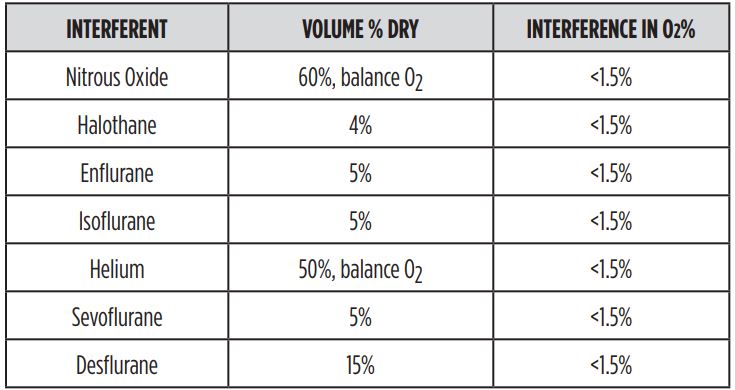
Because of the unique chemistry of the oxygen sensors provided with the MaxBlend Lite, there are no significant effects when exposed to commonly used anesthetic gases, however, the monitor is not designed for exposure to flammable gas mixtures (See WARNING page II).
10.0 SPARE PARTS AND ACCESSORIES

Repair of this equipment must be preformed by a Maxtec Certified Service Technician experienced in repair of this device.
Equipment in need of repair shall be sent to:
Maxtec1.800.748.5355Service Department2305 South 1070 WestSalt Lake City, UT 84119(Include RMA number issued by Customer Service)
11.0 THEORY OF OPERATION
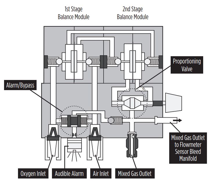
11.1 Operational Diagram
11.2 Mixing Operation
The MaxBlend Lite depends on a common air/oxygen blender for the mixing operation. The diagram above depicts the function of a common blender. Blenders typically utilize two 50 PSIG (3.4 BAR) gas sources. The two gas sources enter through the air and oxygen inlet connectors located on the bottom of the blender. Each inlet connector incorporates a particulate filter. Once through the filters, each gas passes through a duckbill check valve, which prevents possible reverse gas flow from either the air or the oxygen supply systems.The two gases then pass through a two-stage balance regulator. The purpose of this regulator is to equalize the operating pressures of the air and oxygen gas sources. Once these pressures have been balanced, the gases are proportioned according to the oxygen concentration selected on the oxygen concentration selection knob. The oxygen concentration knob allows the clinician to select a desired oxygen concentration from 21% to 100% O2. From this point, the mixed gas flows to the outlet port.
11.3 Gas Outlet
There is one gas outlet on the MaxBlend Lite on the bottom of the acrylic flowmeter. The blender may have one or more additional gas outlets. Please refer to the blender’s instructions for use for details on use of the blender and its auxiliary outlet ports.Regardless of whether or not the outlet has any device connected to it, a minimal gas bleed flow of 0.1 LPM flows form the MaxBlend Lite sensor port on the left side of the blender. It is from this bleed flow that the gas is analyzed by the oxygen sensor. In addition a toggle switch is provided allowing the user to activate an additional gas bleed which ensures the blender has sufficient flow to function accurately when the total flow delivered to the patient is below a certain minimum threshold. For a low flow blender this additional bleed should be activated if the total flow delivered to the patient is less than 3LPM.For a high flow blender the additional bleed should be activated if the total flow delivered to the patient is less than 15LPM. At delivered flows greater than these limits, the bleed toggle can be deactivated to conserve oxygen.
![]() CAUTION: Failure to activate the bleed as described above may result in inaccurate oxygen concentrations from the blender. However, the MaxBlend Lite will always display the actual delivered concentration.
CAUTION: Failure to activate the bleed as described above may result in inaccurate oxygen concentrations from the blender. However, the MaxBlend Lite will always display the actual delivered concentration.
11.4 Alarm/Bypass Function
The MaxBlend Lite depends on the air/oxygen blender for the alarm/bypass function. Common blenders have a pressure differential alarm which provides an audible alarm if gas source pressures differ by 20 PSI (1.3 BAR) (nominal) or more, or if there is a gas supply failure of one of the source gases. This alarm is generated by a reed alarm located in a cap on the bottom of the blender.The primary purpose of the alarm is to audibly warn the operator of an excessive pressure drop or depletion of either source gas pressure. Should both gas pressures increase or decrease simultaneously, an alarm will not activate. If either source gas pressure drops, the outlet pressure will drop similarly as the mixed gas is always balanced to that of the lower gas source.The gas bypass function operates in unison with the alarm. Once the pressure alarm is activated, the bypass function is actuated and the gas with the higher pressure flows directly to the outlet port, bypassing the mixing function of the blender. The oxygen concentration flowing out of the blender will be that of the gas with the higher pressure. In the alarm/bypass mode, the blender will deliver oxygen (100%) or medical air (21%) until pressures have been restored to a differential of 6 PSI or less (0.4 BAR). If the blender is set to deliver 21% and the oxygen source pressure is reduced enough to produce a 20 PSI (1.3 BAR) differential, the unit may not alarm because it will continue to deliver 21% concentration according to the setting.If the setting is moved slightly from 21%, the pressure differential alarm will sound. Similarly, if the MaxBlend Lite is set to deliver 100% and the air source pressure is reduced or lost, the unit may not alarm because it will continue to deliver 100% concentration.
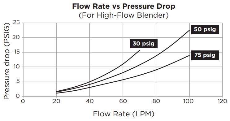
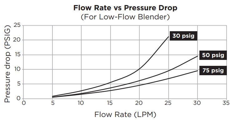
12.0 FLOW CHARACTERISTICS
The following flow characteristics are based on use with a typical blender. The outlet pressure of the blender decreases as the total flow rate increase. The total flow rate is the measurement of the total flow from all outlet ports. The charts below indicate the typical pressure drop that occurs for both low flow and high flow models at 3 inlet pressure settings; 30 PSIG (2.07 BAR), 50 PSIG (3.45 BAR), and 75 PSIG (5.17 BAR).
The fixed acrylic flow meter on the left side of the MaxBlend Lite has been pressure compensated to accommodate for the pressure loss through the blender at each flow rate, using an inlet pressure of 50 PSIG.
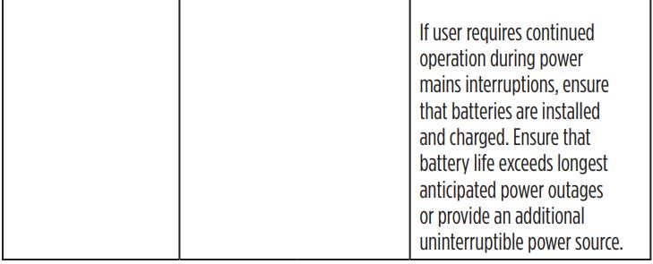
13.0 ELECTROMAGNETIC COMPATABILITY
The information contained in this section (such as separation distances) is in general specifically written with regard to the MaxBlend Lite. The numbers provided will not guarantee faultless operation but should provide reasonable assurance of such. This information may not be applicable to other medical electrical equipment; older equipment may be particularly susceptible to interference.Note: Medical electrical equipment requires special precautions regarding electromagnetic compatibility (EMC) and needs to be installed and put into service according to the EMC information provided in this document and the remainder of the instructions for use this device.Portable and mobile RF communications equipment can affect medical electrical equipment.Cables and accessories not specified within the instructions for use are not authorized. Using other cables and/or accessories may adversely impact safety, performance and electromagnetic compatibility (increased emission and decreased immunity).Care should be taken if the equipment is used adjacent to or stacked with other equipment; if adjacent or stacked use is inevitable, the equipment should be observed to verify normal operation in the configuration in which it will be used.

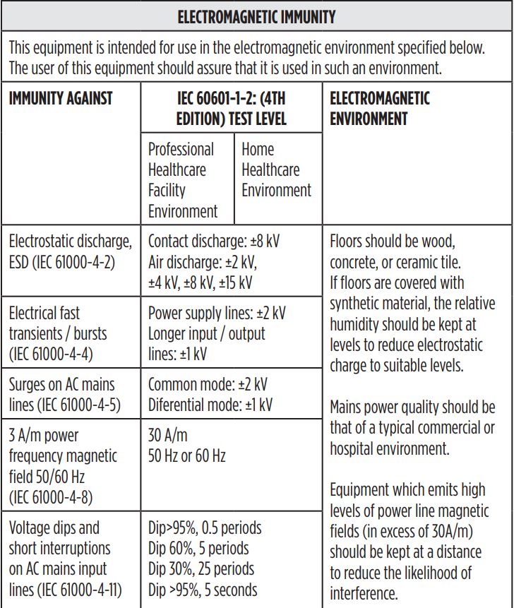
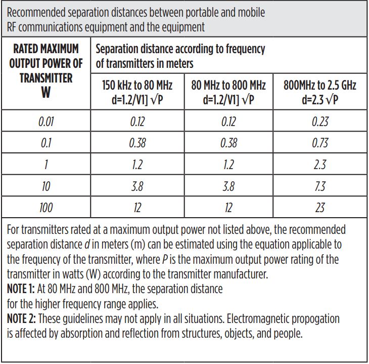
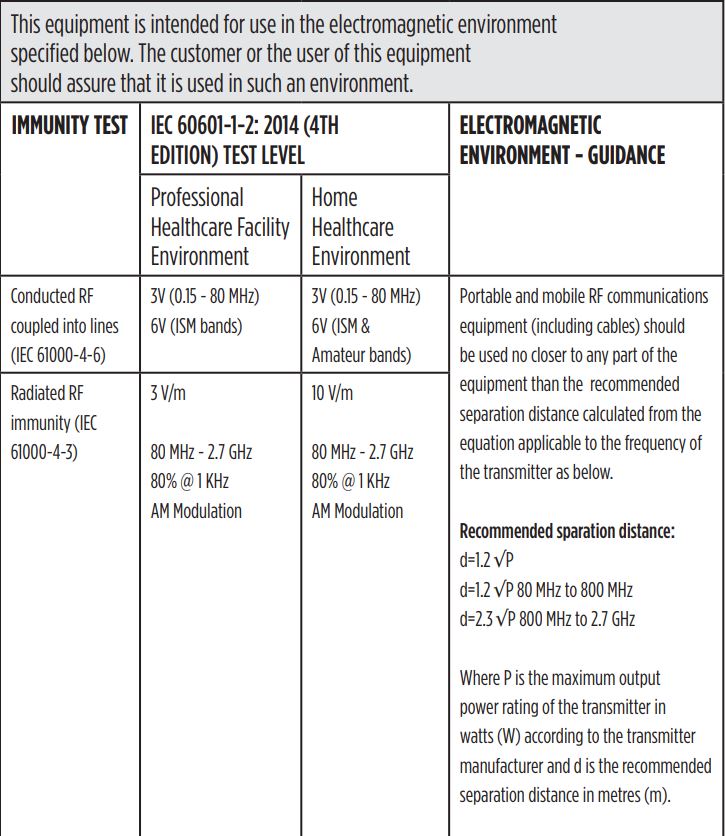

The ISM (industrial, scientific and medical) bands between 150 kHz and 80 MHz are 6,765 MHz to 6,795 MHz; 13,553 MHz to 13,567 MHz; 26,957 MHz to 27,283 MHz; and 40,66 MHz to 40,70 MHzField strengths from fixed transmitters, such as base stations for radio (cellular/cordless) telephones and land mobile radios, amateur radio, AM and FM radio broadcast and TV broadcast cannot be predicted theoretically with accuracy. To assess the electromagnetic environment due to fixed RF transmitters, an electromagnetic site survey should be considered. If the measured field strength in the location in which the equipment is used exceeds the applicable RF compliance level above, the equipment should be observed to verify normal operation. If abnormal performance is observed, additional measures may be necessary, such as reorienting or relocating the equipment.
![]()
2305 South 1070 West Salt Lake City, Utah 84119(800) 748-5355www.maxtec.com
References
[xyz-ips snippet=”download-snippet”]