maxtec MaxO2+ Medical Oxygen Analyzer Instructions
NOTE: The latest edition of this operating manual can be downloaded from our website at www.maxtec.com
This manual describes the function, operation and maintenance of the Maxtec Model MaxO2+ A and AE oxygen analyzer. The MaxO2+ family of Oxygen Analyzers utilizes the Maxtec Max-250 oxygen sensor and is engineered for fast response, maximum reliability and stable performance. The MaxO2+ is designed as a tool for use by qualified personnel to spot-check or measure oxygen concentration of delivered air/oxygen mixtures. The MaxO2+ A and AE Analyzers are not intended for use in continuous monitoring of oxygen delivery to a patient.
![]() Product Disposal Instructions:The sensor, batteries, and circuit board are not suitable for regular trash disposal. Return sensor to Maxtec for proper disposal or dispose according to local guidelines. Follow local guidelines for disposal of other components.
Product Disposal Instructions:The sensor, batteries, and circuit board are not suitable for regular trash disposal. Return sensor to Maxtec for proper disposal or dispose according to local guidelines. Follow local guidelines for disposal of other components.
CLASSIFICATION
Protection against electric shock…………………………………………………………………….. ………II, Type BProtection against water………………………………………………………………………………………………….IPX1Mode of operation………………………………………………………………………………………………..ContinuousSterilization…………………………………………………………………………………………………….See section 7.0Flammable anesthetic mixture……………………………………………..Not suitable for use in presence of a flammable anesthetic mixture
WARRANTY
The MaxO2+ Analyzer is designed for medical oxygen delivery equipment and systems. Under normal operating conditions, Maxtec warrants the MaxO2+ Analyzer to be free from defects of workmanship or materials for a period of 2-years from the date of shipment from Maxtec, provided that the unit is properly operated and maintained in accordance with Maxtec’s operating instructions. Based on Maxtec product evaluation, Maxtec’s sole obligation under the foregoing warranty is limited to making replacements, repairs, or issuing credit for equipment found to be defective. This warranty extends only to the buyer purchasing the equipment directly from Maxtec or through Maxtec ‘s designated distributors and agents as new equipment.
Maxtec warrants Max-250 oxygen sensor in the MaxO2+ Analyzer to be free from defects in material and workmanship for a period of 2-years from Maxtec’s date of shipment in a MaxO2+ unit. Should a sensor fail prematurely, the replacement sensor is warranted for the remainder of the original sensor warranty period.
Routine maintenance items, such as batteries, are excluded from warranty. Maxtec and any other subsidiaries shall not be liable to the purchaser or other persons for incidental or consequential damages or equipment that has been subject to abuse, misuse, mis-application, alteration, negligence or accident.These warranties are exclusive and in lieu of all other warranties, expressed or implied, including warranty of merchantability and fitness for a particular purpose.
WARNINGS 
Indicates a potentially hazardous situation, if not avoided, could result in death or serious injury.
- Never install the sensor in a location that will expose the sensor to patient’s exhaled breath or secretions, unless you intend to dispose of the sensor, flow diverter and tee adapter.
- Improper use of this device can cause inaccurate oxygen readings which can lead to improper treatment, hypoxia or hyperoxia. Follow the procedures outlined in this user manual.
- Not for use in an MRI environment.
- Device specified for dry gas only.
- Never allow an excess length of tubing, lanyard or sensor cable near the patient’s head or neck, which may result in strangulation.
- Before use, all individuals who will be using the MaxO2+ must become thoroughly familiar with the information contained in this Operation Manual. Strict adherence to the operating instructions is necessary for safe, effective product performance.
- This product will perform only as designed if installed and operated in accordance with the manufacturer’s operating instructions.
- Use only genuine Maxtec accessories and replacement parts. Failure to do so may seriously impair the analyzer’s performance. Repair of this equipment must be performed by a qualified service technician experienced in repair of portable hand held medical equipment.
- Calibrate the MaxO2+ weekly when in operation, or if environmental conditions change significantly. (i.e., Elevation, Temperature, Pressure, Humidity — refer to Section 3.0 of this manual).
- Use of the MaxO2+ near devices that generate electrical fields may cause erratic readings.
- If the MaxO2+ is ever exposed to liquids (from spills or immersion) or to any other physical abuse, turn the instrument OFF and then ON. This will allow the unit to go through its self test to assure everything is operating correctly.
- Never autoclave, immerse or expose the MaxO2+ (including sensor) to high temperatures (>70°C). Never expose the device to pressure, irradiation vacuum, steam, or chemicals.
- This device does not contain automatic barometric pressure compensation.
- Although the sensor of this device has been tested with various anesthesia gases including nitrous oxide, Halothane, Isoflurane, Enflurane, Sevoflurane and Desflurane and found to have acceptably low interference, the device in entirety (including electronics) is not suitable for use in the presence of a flammable anesthetic mixture with air or with oxygen or nitrous oxide. Only the threaded sensor face, flow diverter, and “T” adapter may be allowed to contact such a gas mixture.
- Not for use with inhalation agents. Operating the device in flammable or explosive atmospheres may result in fire or explosion.
- This product is not intended as a life-sustaining or life-supporting device.
- Medical oxygen should meet the requirements of USP.
- The MaxO2+ and sensor are non-sterile devices.
- In the event of exposure to an ELECTROMAGNETIC DISTURBANCE the analyzer may display an E06 or E02 error message. If this occurs, turn the instrument OFF, remove the batteries and wait 30 seconds. Then, re-load the batteries and allow the unit to go through its self-test diagnostics to make sure= everything is functioning correctly.
CAUTIONS
Indicates a potentially hazardous situation, if not avoided, could result in minor or moderate injury and property damage.
- Federal Law (USA) restricts this device to sale by or on the order of a physician.
- Replace the batteries with recognized high quality AA Alkaline or Lithium batteries. DO NOT use rechargeable batteries.
- If the unit is going to be stored (not in use for 1 month), we recommend that you remove the batteries to protect the unit from potential battery leakage.
- The Maxtec Max-250 oxygen sensor is a sealed device containing a mild acid electrolyte, lead (Pb), and lead acetate. Lead and lead acetate are hazardous waste constituents and should be disposed of properly, or returned to Maxtec for proper disposal or recovery. DO NOT use ethylene oxide sterilization. DO NOT immerse the sensor in any cleaning solution, autoclave or expose the sensor to high temperatures.
- Dropping sensor can adversely affect its performance.
- The device will assume a percent oxygen concentration when calibrating. Be sure to apply 100% oxygen, or ambient air concentration to the device during calibration or the device will not calibrate correctly.
NOTE: This product is latex free.
SYMBOL GUIDE
The following symbols and safety labels are found on the MaxO2+:
|
Follow instructions for use |
On/Off Button |
|
Warning |
Calibration Button |
|
Meets ETL standards |
Do not throw away. Follow local guidelines for disposal |
|
DO NOT |
Percent |
| Low Battery |
Serial Number |
|
Calibration Required |
Lot code/Batch code |
|
Caution |
Ingress Protection Rating |
| Federal law (USA) restricts this device to sale by or on order of a physician |
Authorized Representative in the European Community |
|
Manufacturer |
Catalog Number |
|
Date of Manufacture |
Medical Device |


Overview
Indications for Use
The MaxO2+ oxygen analyzer is intended for spot checking of the concentration of oxygen being delivered to patients ranging from newborns to adults. It can be used in pre-hospital, hospital, and sub-acute settings. The MaxO2+ is not a life supporting device.
Base Unit Description
The MaxO2+ analyzer provides unparalleled performance and reliability due to an advanced design that includes the following features and operational benefits.
- Extra-life oxygen sensor of approximately 1,500,000 O2 percent hours (2-yearwarranty)
- Durable, compact design that permits comfortable, hand-held operation and easy to clean
- Operation using only two AA Alkaline batteries (2 x 1.5 Volts) for approximately 5000 hours of performance with continuous use. For extra extended long life, two AA Lithium batteries may be used.
- Oxygen-specific, galvanic sensor that achieves 90% of final value in approximately 15 seconds at room temperature.
- Large, easy-to-read, 3 1/2-digit LCD display for readings in the 0-100% range.
- Simple operation and easy one-key calibration.
- Self-diagnostic check of analog and microprocessor circuitry.
- Low battery indication.
- Calibration reminder timer that alerts the operator, using a calibration icon on the LCD display, to perform a unit calibration.
Component Identification
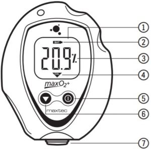
- 3-DIGIT LCD DISPLAYThe 3 digit liquid crystal display (LCD) provides direct readout of oxygen concentrations in the range of 0 – 105.0% (100.1% to 105.0% used for calibration determination purposes). The digits also display error codes and calibration codes as necessary.
- LOW BATTERY INDICATORThe low battery indicator is located at the top of the display and is only activated when the voltage on the batteries is below a normal operating level.
- “%” SYMBOLThe “%” sign is located to the right of the concentration number and ispresent during normal operation.
- CALIBRATION SYMBOL- The calibration symbol is located at the bottom of the display and is timed to activate when a calibration is necessary.
- ON/OFF KEY- This key is used to turn the device on or off.
- CALIBRATION KEY- This key is used to calibrate the device. Holding the key for more than three seconds will force the device to enter a calibration mode.
- SAMPLE INLET CONNECTIONThis is the port at which the device is connected to determine oxygen concentration.
Max-250 Oxygen Sensor
The Max-250+ oxygen sensor offers stability and extra life. The Max-250+ is a galvanic, partial pressure sensor that is specific to oxygen. It consists of two electrodes (a cathode and an anode), a teflon membrane and an electrolyte. Oxygen diffuses through the teflon membrane and immediately reacts at a gold cathode. Concurrently, oxidation occurs electrochemically at the lead anode, generating an electrical current and providing a voltage output. Electrodes are immersed in a unique gelled weak acid electrolyte which is responsible for the sensors long life and motion insensitive characteristic. Since the sensor is specific to oxygen, the current generated is proportional to the amount of oxygen present in the sample gas. When no oxygen is present, there is no electrochemical reaction and therefore, negligible current is produced. In this sense, the sensor is self-zeroing.
OPERATING INSTRUCTIONS
Getting Started
Protect TapePrior to turning on the unit, a protective film covering the threaded sensor face must be removed. After removing the film, wait approximately 20 minutes for the sensor to reach equilibrium.
Automatic CalibrationAfter the unit is turned on it will automatically calibrate to room air. The display should be stable and reading 20.9%.
![]() CAUTION: The device will assume a percent oxygen concentration when calibrating. Be sure to apply 100% oxygen, or ambient air concentration to the device during calibration or the device will not calibrate correctly.
CAUTION: The device will assume a percent oxygen concentration when calibrating. Be sure to apply 100% oxygen, or ambient air concentration to the device during calibration or the device will not calibrate correctly.
To check the oxygen concentration of a sample gas: (after the unit has been calibrated):
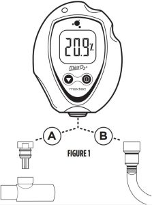
- Connect the Tygon tubing to the bottom of the analyzer by threading the barbed adapter onto the oxygen sensor. (FIGURE 1, B)
- Attach the other end of the sample hose to the sample gas source and initiate flow of the sample to the unit at a rate of 1-10 liters per minute (2 liters per minute is recommended).
- Using the “ON/OFF” key, make sure the unit is in the power “ON” mode.
- Allow the oxygen reading to stabilize. This will normally take about 30 seconds or more.
Calibrating the MaxO2+ Oxygen Analyzer
NOTE: We recommend use of medical grade USP or >99% purity oxygen when calibrating the MaxO2+.
The MaxO2+ Analyzer should be calibrated upon initial power-up. Thereafter, Maxtec recommends calibration on a weekly basis. To serve as a reminder, a one week timer is started with each new calibration. At the end of one week a reminder icon “![]() ” will appear on the bottom of the LCD. Calibration is recommended if the user is unsure when the last calibration procedure was performed, or if the measurement value is in question. Start calibration by pressing the
” will appear on the bottom of the LCD. Calibration is recommended if the user is unsure when the last calibration procedure was performed, or if the measurement value is in question. Start calibration by pressing the ![]() Calibration key for more than 3 seconds. The MaxO2+ will automatically detect if you are calibrating with 100% oxygen or 20.9% oxygen (normal air).
Calibration key for more than 3 seconds. The MaxO2+ will automatically detect if you are calibrating with 100% oxygen or 20.9% oxygen (normal air).![]() DO NOT attempt to calibrate to any other concentration.
DO NOT attempt to calibrate to any other concentration.
For hospital and home care a new calibration is required when:
- The measured O2 percentage in 100% O2 is below 97.0% O2.
- The measured O2 percentage in 100% O2 is above 103.0% O2.
- The CAL reminder Icon is blinking at the bottom of the LCD.
- If you are unsure about the displayed O2 percentage. (see Factors influencing accurate readings.)
For ID testing, (or optimum accuracy) a new calibration is required when:
- The measured O2 percentage in 100% O2 is below 99.0% O2.
- The measured O2 percentage in 100% O2 is above 101.0% O2.
- The CAL reminder Icon is blinking at the bottom of the LCD.
- If you are unsure about the displayed O2 percentage (see Factors influencing accurate readings).
A simple calibration may be made with the sensor open to static ambient air. For optimum accuracy Maxtec recommends that the Sensor be placed in a closed loop circuit where gas flow is moving across the sensor in a controlled manner. Calibrate with the same type of circuit and flow that you will use in taking your readings.
In Line Calibration (Flow Diverter – Tee Adapter)
- Attach the diverter to the MaxO2+ by threading it on to the bottom of the sensor.
- Insert the MaxO2+ in the center position of the tee adapter. (FIGURE 1, A)
- Attach an open-ended reservoir to the end of the tee adapter. Then start the calibration flow of oxygen at two liters per minute.***Six to 10 inches of corrugated tubing works well as a reservoir. A calibration oxygen flow to the MaxO2+ of two liters per minute is recommended to minimize the possibility of obtaining a “false” calibration value.
- Allow the oxygen to saturate the sensor. Although a stable value is usually observed within 30 seconds, allow at least two minutes to ensure that the sensor is completely saturated with the calibration gas.
- If the MaxO2+ is not already turned on, do so now by pressing the analyzer “ON” button.
- Press the Cal button on the MaxO2+ until you read the word CAL on the analyzer display. This can take approximately 3 seconds. The analyzer will now look for a stable sensor signal and a good reading. When obtained, the analyzer will display the calibration gas on the LCD.
NOTE: Analyzer will read “Cal Err St” if the sample gas has not stabilized.
Direct Flow Calibration (Barb)
- Attach the Barbed Adapter to the MaxO2+ by threading it on to the bottom of the sensor.
- Connect the Tygon tube to the barbed adapter. (FIGURE 1, B)
- Attach the other end of the clear sampling tube to a source of oxygen with a known oxygen concentration value. Initiate flow of the calibration gas to the unit. Two liters per minute is recommended.
- Allow the oxygen to saturate the sensor. Although a stable value is usually observed within 30 seconds, allow at least two minutes to ensure that the sensor is completely saturated with the calibration gas.
- If the MaxO2+ is not already turned on, do so now by pressing the analyzer “ON” button.
- Press the Cal button on the MaxO2+ until you read the word CAL on the analyzer display. This can take approximately 3 seconds. The analyzer will now look for a stable sensor signal and a good reading. When obtained, the analyzer will display the calibration gas on the LCD.
FACTORS INFLUENCING ACCURATE READINGS
Elevation/Pressure Changes
- Changes in elevation result in a reading error of approximately 1% of reading per 250 feet.
- In general, calibration of the instrument should be performed when elevation at which the product is being used changes by more than 500 feet.
- This device does not automatically compensate for changes in barometric pressure or altitude. If the device is moved to a location of a different altitude, it must be recalibrated before use.
Temperature Effects
The MaxO2+ will hold calibration and read correctly within ±3% when at thermal equilibrium within the operating temperature range. The device must be thermally stable when calibrated and allowed to thermally stabilize after experiencing temperature changes before readings are accurate. For these reasons, the following is recommended:
- For best results, perform the calibration procedure at a temperature close to the temperature where analysis will occur.
- Allow adequate time for the sensor to equilibrate to a new ambient temperature.
![]() CAUTION: “CAL Err St” may result from a sensor that has not reached thermal equilibrium.When used in a breathing circuit, place the sensor upstream of the heater.
CAUTION: “CAL Err St” may result from a sensor that has not reached thermal equilibrium.When used in a breathing circuit, place the sensor upstream of the heater.
Pressure Effects
Readings from the MaxO2+ are proportional to the partial pressure of oxygen. The partial pressure is equal to the concentration times the absolute pressure.
Thus, the readings are proportional to the concentration if the pressure is held constant. Therefore, the following are recommended:
- Calibrate the MaxO2+ at the same pressure as the sample gas.
- If sample gases flow through tubing, use the same apparatus and flow rates when calibrating as when measuring.
Humidity Effects
Humidity (non-condensing) has no effect on the performance of the MaxO2+ other than diluting the gas, as long as there is no condensation. Depending on the humidity, the gas may be diluted by as much as 4%, which proportionally reduces the oxygen concentration. The device responds to the actual oxygen concentration rather than the dry concentration. Environments where condensation may occur are to be avoided since moisture may obstruct passage of gas to the sensing surface, resulting in erroneous readings and slower response time. For this reason, the following is recommended:
- Avoid usage in environments greater than 95% relative humidity.
- When used in a breathing circuit, place the sensor upstream of the humidifier.
HELPFUL HINT: Dry sensor by lightly shaking moisture out, or flow a dry gas at two liters per minute across the sensor membrane.
CALIBRATION ERRORS AND ERROR CODES
The MaxO2+ analyzers have a self test feature built into the software to detect faulty calibrations, oxygen sensor failures, and low operating voltage. These are listed below, and include possible actions to take, if an error code occurs.
E02: No sensor attached
- MaxO2+A: Open unit and disconnect and reconnect sensor. Unit should perform an auto calibration and should read 20.9%. If not, contact Maxtec Customer Service for possible sensor replacement.
- MaxO2+AE: Disconnect and reconnect external sensor. Unit should perform an auto calibration, and should read 20.9%. If not, contact Maxtec Customer Service for possible sensor replacement or cable replacement.
E03: No valid calibration data available
- Make sure unit has reached thermal equilibrium. Press and hold the Calibration Button for three seconds to manually force a new calibration.
E04: Battery below minimum operating voltage
- Replace batteries.
E06: Non-compatible oxygen sensor, see note below.
- Replace batteries.
CAL ERR ST: O2 Sensor reading not stable
- Wait for displayed oxygen reading to stabilize, when calibrating the device at 100% oxygen.
- Wait for unit to reach thermal equilibrium, (Please note that this can take up to one half hour, if the device is stored in temperatures outside the specified operating temperature range).
CAL ERR LO: Sensor voltage too low
- Press and hold the Calibration Button for three seconds to manually force a new calibration. If unit repeats this error more than three times, contact Maxtec Customer Service for possible sensor replacement.
CAL ERR HI: Sensor voltage too high
- Press and hold the Calibration Button for three seconds to manually force a new calibration. If unit repeats this error more than three times, contact Maxtec Customer Service for possible sensor replacement.
CAL ERR BAT: Battery voltage too low to recalibrate
- Replace batteries.
NOTE: If you receive a E01, E05, or an E07 error code, correct by ensuring the calibration gas is either room air or 100% oxygen. Also ensure the calibration gas flow, pressure and concentration is constant. Allow sufficient time for the sensor to stabilize in the calibration gas and with room temperature, then attempt to calibrate again.If these steps do not correct the error, contact Maxtec for technical support.
NOTE: Use only a Maxtec approved Max-550E sensor called out in Section 9.0 of the Spare Parts List. The Max550E sensor is equipped with an authentication chip to ensure the monitor is used with an approved sensor.
NOTE: Correcting E02, E06, or E07 errors:
- Disconnect the sensor and reconnect, making sure the male plug is fully inserted into the receptacle before tightening the threaded locking shroud. The analyzer should now perform a new calibration with the error cleared.
- If the error still persists, remove the batteries, wait 30 seconds, then reinstall to perform a factory reset and diagnostic on the analyzer. The analyzer should again perform a new calibration with the error cleared.
- Contact Maxtec Customer Service Department if the error code cannot be cleared.
CHANGING THE BATTERIES
Batteries should be changed by service personnel.
- Use only brand name batteries.
- Replace with two AA batteries and insert per orientation marked on the device.
Should the batteries require changing, the device will indicate this in one of two ways:
- The battery icon on the bottom of the display will begin to flash. This icon will continue to flash until the batteries are changed. The unit will continue to function normally for approx. 200 hours.
- If the device detects a very low battery level, an error code of “E04” will be present on the display, and the unit will not function until the batteries are changed.
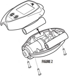
To change the batteries, begin by removing the three screws from the back of the device. A #1 Phillips screwdriver is required to remove these screws.
Once the screws are removed, gently separate the two halves of the device.
The batteries can now be replaced from the back half of the case. Be sure to orient the new batteries as indicated in the embossed polarity on the back case.
NOTE: If the batteries are installed incorrectly the batteries will not make contact and the device will not operate.
Carefully, bring the two halves of the case together while positioning the wires so they are not pinched between the two case halves.
The gasket separating the halves will be captured on the back case half.
Reinsert the three screws and tighten until the screws are snug. (FIGURE 2).
The device will automatically perform a calibration and begin displaying % of oxygen.
HELPFUL HINT: If unit does not function, verify that the screws are tight to allow proper electrical connection.
HELPFUL HINT (MAXO2+ AE): Before closing the two case halves together, verify that the keyed slot on top of the coiled cable assembly is engaged on the small tab located on the back case. This is designed to position the assembly in the correct orientation and prevent it from rotating. Improper positioning could hinder the case halves from closing and prevent operation when tightening the screws.
CHANGING THE OXYGEN SENSOR
MaxO2+A Model
Should the oxygen sensor require changing, the device will indicate this by presenting “Cal Err lo” on the display after initiating a calibration.To change the oxygen sensor, begin by removing the three screws from the back of the device.
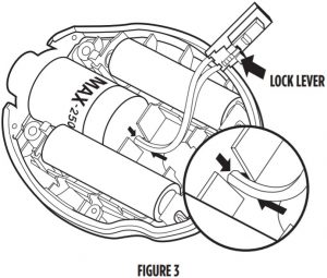
A #1 Phillips screwdriver is required to remove these screws.Once the screws are removed, gently separate the two halves of the device.Disconnect the oxygen sensor from the printed circuit board by pressing the unlock lever first and then pulling the connector out of the receptacle. The oxygen sensor can now be replaced from the back half of the case.
HELPFUL HINT: Be sure to orient the new sensor by aligning the red arrow on the sensor with the arrow in the back case. A small tab is located on the back case that is designed to engage the sensor and prevent it from rotating within the case. (FIGURE 3)
NOTE: If the oxygen sensor is installed incorrectly, the case will not come back together and the unit may be damaged when the screws are reinstalled.
NOTE: If the new sensor has red tape over the outside, remove it, then wait 30 minutes before calibrating.Reconnect the oxygen sensor to the connector on the printed circuit board. Carefully bring the two halves of the case together while positioning the wires to ensure they are not pinched between the two case halves. Make sure the sensor is fully inserted and in the proper orientation.Reinsert the three screws and tighten until the screws are snug. Verify the unit operates properly. The device will automatically perform a calibration and begin displaying % of oxygen.
MaxO2+AE Model
Should the oxygen sensor require changing, the device will indicate this by presenting “Cal Err lo” on the display.Unthread the sensor from the cable by rotating the thumbscrew connector counterclockwise and pull the sensor from the connection. Replace the new sensor by inserting the electrical plug from the coiled cord into the receptacle on the oxygen sensor. Rotate the thumbscrew clockwise until snug. The device will automatically perform a calibration and begin displaying % of oxygen.
CLEANING AND MAINTENANCE
Store the MaxO2+ analyzer in a temperature similar to its ambient environment of daily use.The instruction given below describes the methods to clean and disinfect the instrument, sensor and its accessories (e.g. flow diverter, tee adapter):
Instrument Cleaning:
- When cleaning or disinfecting the exterior of the MaxO2+ analyzer, take appropriate care to prevent any solution from entering the instrument. DO NOT immerse unit in fluids.
- The MaxO2+ analyzer surface may be cleaned using a mild detergent and a moist cloth.
- The MaxO2+ analyzer is not intended for steam, ethylene oxide or radiation sterilization.
Oxygen Sensor:
![]() WARNING: Never install the sensor in a location that will expose the sensor to patient’s exhaled breath or secretions, unless you intend to dispose of the sensor, flow diverter and tee adapter after use.
WARNING: Never install the sensor in a location that will expose the sensor to patient’s exhaled breath or secretions, unless you intend to dispose of the sensor, flow diverter and tee adapter after use.
- Clean the sensor with a cloth moistened with isopropyl alcohol (65% alcohol/water solution).
- Maxtec does not recommend use of spray disinfectants because they can contain salts, which can accumulate in the sensor membrane and impair readings.
- The oxygen sensor is not intended for steam, ethylene oxide or radiation sterilization.
Accessories:
STERILIZING: The flow diverter and tee adapter Maxtec recommends that operators carefully examine the flow diverter and tee adapter after sterilization and prior to use to verify that the item is fit for use. The operator should verify that there are no cracks and the item does not show any indiction of material changes or physical damage that may compromise its effective use. Because of the variability of the cleaning, disinfecting and sterilizing processes, Maxtec cannot provide specific sterilization instructions, nor can the sterility of the item be ensured. If the accessory is suspected to be contaminated it should be removed and discarded.
SPECIFICATIONS
Base Unit Specifications
Measurement Range…………………………………………………………………………………………………..0-100% Resolution………………………………………………………………………………………………………………………0.1%Accuracy and Linearity……………………………….1% of full scale at constant temperature, R.H. andpressure when calibrated at full scaleTotal Accuracy………………………………….±3% actual oxygen level over full operating temp rangeResponse Time………………………………….90% of final value in approximately 15 seconds at 23˚CWarm-up Time………………………………………………………………………………………………..None requiredOperating Temperature………………………………………………………………….15˚C – 40˚C (59˚F – 104˚F)Storage Temperature………………………………………………………………………-15˚C – 50˚C (5˚F – 122˚F)Atmospheric Pressure……………………………………………………………………………………800-1013 mBarsHumidity………………………………………………………………………………………..0-95% (non-condensing)Power Requirements…………………………………………………….2, AA Alkaline batteries (2 x 1.5 Volts)Battery Life……………………………………………………approximately 5000 hours with continuous useLow Battery Indication………………………………………………………………..”BAT” icon displayed on LCDSensor Type………………………………………………………………Maxtec Max-250 series galvanic fuel cellExpected Sensor Life……………………………………………….. > 1,500,000 O2 percent hours minimum (2-year in typical medical applications)Drift of Measurement…….< +/-1% of full scale at constant temperature, pressure and humidityA Model Dimensions…………………………….3.0”(W) x 4.0”(H) x 1.5”(D) [76mm x 102mm x 38mm]A Weight………………………………………………………………………………………………………….0.4 lbs. (170g)AE Model Dimensions………………………..3.0”(W) x 36.0”(H) x 1.5”(D) [76mm x 914mm x38mm] ] Height includes external cable length (retracted)AE Weight………………………………………………………………………………………………………..0.6 lbs. (285g)
Sensor Specifications
Type………………………………………………………………………………………..Galvanic fuel sensor (0-100%)Life………………………………………………………………………………………….2-years in typical applications
MAXO2+ SPARE PARTS AND ACCESSORIES
Included With Your Unit
|
PART NUMBER |
ITEM | A MODEL | AE MODEL |
|
R217M40 |
User’s Guide and Operating Instructions |
x | x |
|
RP76P06 |
Lanyard |
x | x |
|
R110P10-001 |
Flow Diverter |
x | x |
|
RP16P02 |
Blue Tee Adapter |
x | x |
|
R217P23 |
Dovetail Bracket |
x |
Standard Replacement Parts and Accessories
|
PART NUMBER |
ITEM |
A MODEL |
AE MODEL |
|
R125P02-011 |
Max-250+ Oxygen Sensor |
x | |
|
R125P03-002 |
Max-250E Oxygen Sensor |
x |
|
|
R115P85 |
Max-250ESF Oxygen Sensor |
x |
|
|
R217P08 |
Gasket |
x |
x |
|
RP06P25 |
#4-40 Pan Head Stainless Steel Screw |
x |
x |
|
R217P16-001 |
Front Assembly (Includes Board & LCD) |
x |
x |
|
R217P11-002 |
Back Assembly |
x |
x |
|
R217P24 |
Coiled Cable Assembly |
x |
|
|
R217P09-001 |
Overlay |
x |
x |
Optional Accessories
Optional Adapters
|
PART NUMBER |
ITEM |
|
RP16P02 |
Blue Tee Adapter |
|
R103P90 |
Perfusion Tee Adapter |
|
RP16P05 |
Pediatric Tee Adapter |
|
R207P17 |
Threaded Adapter with Tygon Tubing |
Mounting Options (requires dovetail R217P23)
|
PART NUMBER |
ITEM |
|
R206P75 |
Pole Mount |
|
R205P86 |
Wall Mount |
|
R100P10 |
Rail Mount |
|
R206P76 |
Horizontal Pole Mount |
NOTE: Repair of this equipment must be performed by a qualified service technician experienced in repair of portable hand held medical equipment.Equipment in need of repair shall be sent to:MaxtecService Department2305 South 1070 WestSalt Lake City, Ut 84119(Include RMA number issued by customer service)
ELECTROMAGNETIC COMPATIBILITY
The information contained in this section (such as separation distances) is in general specifically written with regard to the MaxO2+ A/AE. The numbers provided will not guarantee faultless operation but should provide reasonable assurance of such. This information may not be applicable to other medical electrical equipment; older equipment may be particularly susceptible to interference.
Note: Medical electrical equipment requires special precautions regarding electromagnetic compatibility (EMC) and needs to be installed and put into service according to the EMC information provided in this document and the remainder of the instructions for use this device.
Portable and mobile RF communications equipment can affect medical electrical equipment.
Cables and accessories not specified within the instructions for use are not authorized. Using other cables and/or accessories may adversely impact safety, performance and electromagnetic compatibility (increased emission and decreased immunity).
Care should be taken if the equipment is used adjacent to or stacked with other equipment; if adjacent or stacked use is inevitable, the equipment should be observed to verify normal operation in the configuration in which it will be used.
|
ELECTROMAGNETIC EMISSIONS |
||
|
This equipment is intended for use in the electromagnetic environment specified below. The user of this equipment should assure that it is used in such an environment. |
||
|
EMISSIONS |
COMPLIANCE ACCORDING TO |
ELECTROMAGNETIC ENVIRONMENT |
|
RF Emissions (CISPR 11) |
Group 1 |
The MaxO2+ uses RF energy only for its internal function. Therefore, its RF emissions are very low and are not likely to cause any interference in nearby electronic equipment. |
|
CISPR Emissions Classification |
Class A |
The MaxO2+ is suitable for use in all establishments other than domestic and those directly connected to the public low- voltage power supply network that supplies buildings used for domestic purposes. NOTE: The EMISSIONS characteristics of this equipment make it suitable for use in industrial areas and hospitals (CISPR 11 class A). If it is used in a residential environment (for which CISPR 11 class B is normally required) this equipment might not offer adequate protection to radio- frequency communication services. The user might need to take mitigation measures, such as relocating or re orienting the equipment. |
|
Recommended separation distances between portable and mobile RF communications equipment and the equipment |
|||
|
RATED MAXIMUM OUTPUT POWER OF TRANSMITTERW |
Separation distance according to frequency of transmitters in meters |
||
|
150 kHz to 80 MHz d=1.2/V1] ÖP |
80 MHz to 800 MHz d=1.2/V1] ÖP |
800MHz to 2.5 GHz d=2.3 ÖP |
|
|
0.01 |
0.12 |
0.12 |
0.23 |
|
0.1 |
0.38 |
0.38 |
0.73 |
| 1 | 1.2 | 1.2 |
2.3 |
|
10 |
3.8 | 3.8 |
7.3 |
|
100 |
12 |
12 |
23 |
| For transmitters rated at a maximum output power not listed above, the recommended separation distance d in meters (m) can be estimated using the equation applicable to the frequency of the transmitter, where P is the maximum output power rating of the transmitter in watts (W) according to the transmitter manufacturer.
NOTE 1: At 80 MHz and 800 MHz, the separation distance for the higher frequency range applies. NOTE 2: These guidelines may not apply in all situations. Electromagnetic propagation is affected by absorption and reflection from structures, objects, and people. |
|
ELECTROMAGNETIC IMMUNITY |
||
|
This equipment is intended for use in the electromagnetic environment specified below. The user of this equipment should assure that it is used in such an environment. |
||
|
IMMUNITY AGAINST |
IEC 60601-1-2: (4TH EDITION) TEST LEVEL |
ELECTROMAGNETIC ENVIRONMENT |
|
Professional Healthcare Facility Environment |
Home Healthcare Environment |
|
|
Electrostatic discharge, ESD (IEC 61000-4-2) |
Contact discharge: ±8 kV Air discharge: ±2 kV, ±4 kV, ±8 kV, ±15 kV |
Floors should be wood, concrete, or ceramic tile. If floors are covered with synthetic material, the relative humidity should be kept at levels to reduce electrostatic charge to suitable levels. Mains power quality should be that of a typical commercial or hospital environment. Equipment which emits high levels of power line magnetic fields (in excess of 30A/m) should be kept at a distance to reduce the likelihood of interference. If user requires continued operation during power mains interruptions, ensure that batteries are installed and charged. Ensure that battery life exceeds longest anticipated power outages or provide an additional uninterruptible power source. |
|
Electrical fast transients / bursts (IEC 61000-4-4) |
Power supply lines: ±2 kV Longer input / output lines: ±1 kV |
|
|
Surges on AC mains lines (IEC 61000-4-5) |
Common mode: ±2 kV Differential mode: ±1 kV |
|
|
3 A/m power frequency magnetic field 50/60 Hz (IEC 61000-4-8) |
30 A/m 50 Hz or 60 Hz |
|
|
Voltage dips and short interruptions on AC mains input lines (IEC 61000-4-11) |
Dip>95%, 0.5 periods Dip 60%, 5 periods Dip 30%, 25 periods Dip >95%, 5 seconds |
|
This equipment is intended for use in the electromagnetic environment specified below. The customer or the user of this equipment should assure that it is used in such an environment. |
|||
|
IMMUNITY TEST |
IEC 60601-1-2: 2014 (4TH EDITION) TEST LEVEL |
ELECTROMAGNETIC ENVIRONMENT – GUIDANCE |
|
|
Professional Healthcare Facility Environment |
Home Healthcare Environment | ||
|
Conducted RF coupled into lines (IEC 61000-4-6) |
3V (0.15 – 80 MHz)6V (ISM bands) |
3V (0.15 – 80 MHz)6V (ISM & Amateur bands) |
Portable and mobile RF communications equipment (including cables) should be used no closer to any part of the equipment than the recommended separation distance calculated from the equation applicable to the frequency of the transmitter as below. |
| Radiated RF immunity (IEC 61000-4-3) | 3 V/m
80 MHz – 2.7 GHz 80% @ 1 KHz |
10 V/m
80 MHz – 2.7 GHz 80% @ 1 KHz |
|
|
AM Modulation |
AM Modulation |
Recommended separation distance: d=1.2 ÖP d=1.2 ÖP 80 MHz to 800 MHz d=2.3 ÖP 800 MHz to 2.7 GHz |
|
|
Where P is the maximum output power rating of the transmitter in watts (W) according to the transmitter manufacturer and d is the recommended separation distance in meters (m). |
|||
| Field strengths from fixed RF transmitters, as determined by an electromagnetic site survey a, should be less than the compliance level in each frequency range b. | |||
|
Interference may occur in the vicinity of equipment marked with the following symbol: |
The ISM (industrial, scientific and medical) bands between 150 kHz and 80 MHz are 6,765 MHz to 6,795 MHz; 13,553 MHz to 13,567 MHz; 26,957 MHz to 27,283 MHz; and 40,66 MHz to 40,70 MHz.Field strengths from fixed transmitters, such as base stations for radio (cellular/cordless) telephones and land mobile radios, amateur radio, AM and FM radio broadcast and TV broadcast cannot be predicted theoretically with accuracy. To assess the electromagnetic environment due to fixed RF transmitters, an electromagnetic site survey should be considered. If the measured field strength in the location in which the equipment is used exceeds the applicable RF compliance level above, the equipment should be observed to verify normal operation. If abnormal performance is observed, additional measures may be necessary, such as reorienting or relocating the equipment.
Customer Support:
![]() Maxtec2305 South 1070 WestSalt Lake City, Utah 84119USAphone: (800) 748.5355fax: (801) 973.6090email: web: www.maxtec.com
Maxtec2305 South 1070 WestSalt Lake City, Utah 84119USAphone: (800) 748.5355fax: (801) 973.6090email: web: www.maxtec.com
![]()


References
[xyz-ips snippet=”download-snippet”]