maxtec MaxVenturi Oxygen Gas Blender Instructions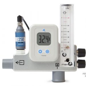
CLASSIFICATION
Protection against electric shock ………… internally powered equipmentProtection against water …………IPX1Mode of operation …………..ContinuousFlammable anesthetic mixture ……….Not suitable for use in the presence of a flammable anesthetic mixture
 Product Disposal Instructions:The sensor, batteries, and circuit board are not suitable for regular trash disposal. Return sensor to Maxtec for proper disposal or dispose according to local guidelines. Follow local guidelines for disposal of other components.
WARRANTY
Provided the device is properly maintained and under normal operating conditions, Maxtec warrants the MaxVenturi to be free from defects of workmanship or materials for a period of 2 years from the date of shipment from Maxtec. Based on Maxtec’s product evaluation, Maxtec’s sole obligation under the foregoing warranty is limited to making replacements, repairs, or issuing credit for equipment found to be defective. This warranty extends only to the buyer purchasing the equipment directly from Maxtec or through Maxtec’s designated distributors and agents as new equipment.
Maxtec warrants the MAX-250E oxygen sensor in the MaxVenturi to be free from defects in material and workmanship for a period of 2 years from Maxtec’s date of shipment in a MaxVenturi unit. Should a sensor fail prematurely, the replacement sensor is warranted for the remainder of the original sensor warranty period.
Routine maintenance items, such as batteries, are excluded from warranty. Maxtec and any other subsidiaries shall not be liable to the purchaser or other persons for incidental or consequential damages or for equipment that has been subject to abuse, misuse, misapplication, alteration, negligence or accident.
THESE WARRANTIES ARE EXCLUSIVE AND IN LIEU OF ALL OTHER WARRANTIES, EXPRESSED OR IMPLIED, INCLUDING WARRANTY OF MERCHANTABILITY AND FITNESS FOR A PARTICULAR PURPOSE.
WARNINGSIndicates a potentially hazardous situation, if not avoided, could result in death or serious injury.
- This device is not intended for use with life supporting devices/systems.
- Failure to comply with the warnings and precautions in this manual could result in instrument damage and possibly jeopardize the wellbeing of the patient and/or health care professional. Improper use of this device can cause inaccuracy of flow and oxygen readings which can lead to improper treatment, hypoxia or hyperoxia, or other patient injury or discomfort. Follow the procedures outlined in this user manual.
- Not for use in an MRI environment.
- If the O2% drifts away from the level to which it was set, check to make sure the nasal prongs on the patient interface are not occluded by sputum or the nasal septum. Flow restriction to the circuit or patient interface will cause the oxygen level to increase. Flow restriction downstream of the venturi unit will not be detected by the flow meter.
- This device does not have any alarms for interruption in oxygen supply.
- Allow oxygen reading to stabilize before adjusting oxygen content.
- This device does not have any alarms for oxygen level high or low alarms.
- Never allow excess length of tubing near the patient’s head or neck which could result in strangulation.
- Use only Maxtec replacement sensors. Use of any other sensor will void warranty and may lead to product damage, product malfunction, improper treatment to patient, hypoxia, or hyperoxia.DO NOT use this device near any type of flame or flammable/explosive substances, vapors or atmosphere. Operating the oxygen analyzer in these environments may result in fire or explosion.
- This device in its entirety (including electronics) is not suitable for use in the presence of flammable anaesthetic mixtures or in an atmosphere of explosive gases. Operating the oxygen analyzer in these environments may result in fire or explosion.DO NOT attach a humidifier or any other source gas to the room air inlet. It should be occupied at all times by the filter listed in the disposables list. The inlet filter prevents entrainment of ambient contamination and silences venturi noise. The filter provided with the MaxVenturi is single-patient use only.
- Use of this device with a pressurized oxygen bottle may result in inaccurate oxygen concentration readings when used above 40 LPM and at high oxygen concentrations. High tank pressures result in cooling oxygen supply temperatures which affect the accuracy of the oxygen sensor. It is suggested that the device be connected with a long supply hose. Use a 15ft supply hose where possible — Maxtec P/N (R127P35).
- Use patient circuits that are approved for use with the manufacturer’s humidifier as listed in their individual instructions for use.DO NOT attempt to clean the inside of the flow meter. If any malfunction is detected in the function of the flow meter, if any debris or contamination is detected in the flow meter, or if the float sticks in the flow tube, discontinue use immediately and return the device to Maxtec for service.
- Never install the sensor in any location other than the sensor port in the device.
SENSOR WARNINGS: The Maxtec MAX-250 oxygen sensor is a sealed device containing a mild acid electrolyte, lead (Pb), and lead acetate. Lead and lead acetate are hazardous waste constituents and should be disposed of properly, or returned to Maxtec for proper disposal or recovery
DO NOT use ethylene oxide sterilization.DO NOT immerse the sensor in any cleaning solution, autoclave or expose the sensor to high temperatures.
- Dropping or severely jarring the sensor after calibration may shift the calibration pointenough to require recalibration
CAUTIONS
Indicates a potentially hazardous situation, if not avoided, could result in minor or moderate injury and property damage.
- Never install the sensor in a location that will expose the sensor to patient exhalation or secretions.
- Only use Maxtec approved accessories and replacement parts. Failure to do so may seriously impair the MaxVenturi’s performance. Repair or alteration of the MaxVenturi beyond the scope of the maintenance instructions or by anyone other than authorized Maxtec servicepersonnel could cause the product to fail to perform as designed.
- Use of the MaxVenturi near devices that generate strong electrical fields may cause erratic readings. In the event of exposure to an ELECTROMAGNETIC DISTURBANCE the analyzer may splay an E02 error message. If this occurs, refer to Section 4.0 for instructions to resolve problem.
- This device has a visual low-battery alarm but no audible alarm.
- Calibrate the MaxVenturi weekly when in operation or if environmental conditions change significantly, i.e., Temperature, Humidity, Barometric Pressure. (refer to Calibration sections of this manual).
- The device will assume a percent oxygen concentration when calibrating. Be sure to apply 100% oxygen or room air concentration to the device during calibration or the device will not calibrate correctly. (See section 2.2)DO NOT immerse the device in any cleaning solution, autoclave or expose the device to high temperatures.
- Use with any other patient interface system may result in false readings from the flow meter.
- The MaxVenturi is not intended for steam, ethylene oxide or radiation sterilization.DO NOT clean with ethanol or acetone.
- After cleaning, and before use on a patient, attach the device to an oxygen supply and allow the device to run at high flow for several minutes to allow any cleaning fluids or vapors to evaporate and be flushed out.
- The device can flow excess oxygen out the entrainment port if the oxygen control knob is turned up too high. This can lead to a minor drop in total air flow to the patient and excess oxygen entering the room environment.
- Federal Law (USA) restricts this device to sale by or on the order of a physician.
ATTENTIONIndicates a potentially hazardous situation, if not avoided, could result in minor or moderate injury and property damage.
- If the MaxVenturi is ever exposed to liquids (spills or immersion) or to any other physical abuse, return to Maxtec for evaluation before use.
- Always remove the batteries to protect the unit from potential leaky battery damage when the unit is going to be stored or not in use for periods exceeding 1 month. Replace dead batteries with high quality AA Alkaline batteries.DO NOT use rechargeable batteries with this device.
- Maxtec cannot warranty any damage resulting from misuse, unauthorized repair or improper maintenance of the instrument.
- This product is Latex free.
- Avoid usage in environments with greater than 95% relative humidity
SYSTEM OVERVIEW
Indications for Use
The MaxVenturi Series is intended for use in high-flow oxygen therapy applications where the ability to deliver diluted oxygen is required. Oxygen being delivered from this device is for adult patients. It is a restricted medical device intended for use by qualified, trained personnel, under the direction of a physician, in professional healthcare settings, i.e., hospital, sub-acute institutions, homecare, and intra-hospital transport. THIS IS NOT INTENDED AS A LIFE SUPPORTING DEVICE.
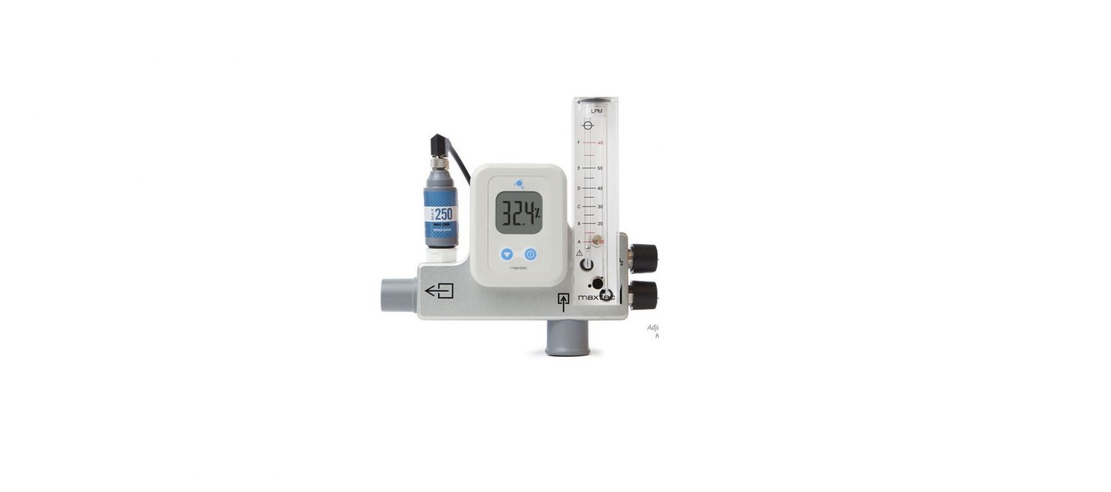
Component Identification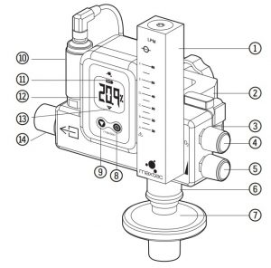
- FLOW METER
- OXYGEN ON/OFF VALVE
- INLET OXYGEN FITTING
- OXYGEN % CONTROL KNOB
 FLOW CONTROL KNOB
- ROOM AIR INLET
- ROOM AIR INLET FILTER
- ON/OFF BUTTON
- CALIBRATION BUTTON
- MAX-250 SERIES OXYGEN SENSOR
- LOW BATTERY INDICATOR
- DIGIT DISPLAY
- CALIBRATION NEEDED INDICATOR
- PATIENT OUTLET
Symbol Guide
The following symbols and safety labels are found on the MaxVenturi:
 Follow instructions for use Follow instructions for use |
 On/Off Button On/Off Button |
|
 Calibration Button Calibration Button |
||
 Meets ETL standards Meets ETL standards |
 Do not throw away. Follow local guidelines for disposal Do not throw away. Follow local guidelines for disposal |
|
 |
Percent | |
 Manufacturer Manufacturer |
||
 Patient Outlet Patient Outlet |
 Date of Manufacture Date of Manufacture |
|
 Read Flow Meter Float at Center Read Flow Meter Float at Center |
 Medical Device Medical Device |
|
 DO NOT DO NOT |
 Serial Number Serial Number |
|
 Federal law (USA) restricts this device to sale by or on order of a physician Federal law (USA) restricts this device to sale by or on order of a physician |
|
Lot code/Batch code |
 Room Air Inlet Room Air Inlet |
 Ingress Protection Rating Ingress Protection Rating |
|
|
|
||
 |
Catalog Number | |
| LMP Liter Per Minute Flow |

 Calibration Required
Product Primary Functions
The primary function of the MaxVenturi is to deliver a mixed gas of oxygen and air to either a heated humidifier system or directly to a patient. One of the primary accessories to the MaxVenturi is a Fisher & Paykel heated humidifier (MR850) and the Optiflow high flow patient interface system and Comfort Flo® Circuits (2415 & 2416) with the Hudson RCI® Neptune® HeatedHumidifier (425-00). Several other patient interface circuits listed in section 2.5 can also be used with the MaxVenturi.
The MaxVenturi flow meter is labeled to compensate for the back pressure by the humidifier/ patient interface system.
- he numbered scale on the flow meter that corresponds to the compensated flow rate for the Fisher & Paykel Optiflow System and Hudson RCI® Neptune® Heated Humidifier.
- The lettered scale on the flow meter corresponds to the flow rates for the other patient interface circuits listed in the chart in Section 2.5.
SET-UP INSTRUCTIONS
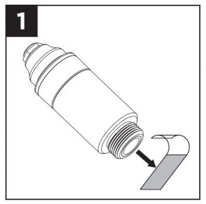
Sensor Installation
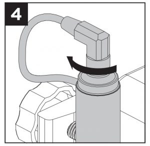
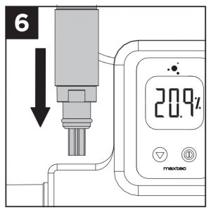
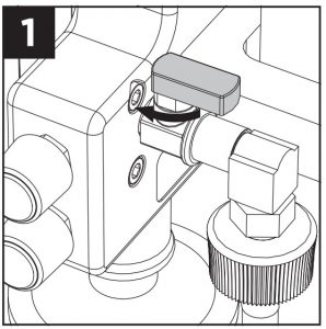
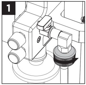
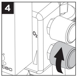
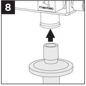
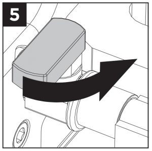
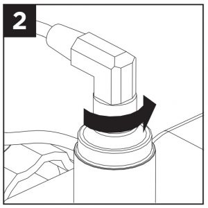
- Remove Max-250 sensor and pull off barrier film.
- Wait 30 to 90 minutes for sensor to stabilize.
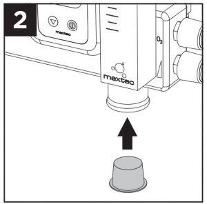
- Attach flow diverter
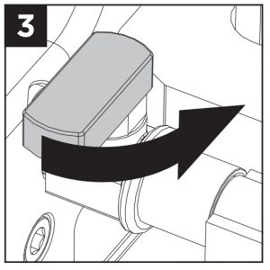
- Attach sensor to sensor cable.
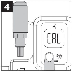
- Press and hold CAL button for three (3) seconds. Wait for display to read “20.9%”.
- Insert sensor into port on MaxVenturi.


CalibrationA new calibration is required when:
- The measured O2 percentage in 100% O2 is below 97.0%.
- The measured O2 percentage in 100% O2 is above 103.0%.
- The CAL reminder icon is blinking at the bottom of the LCD.
- You are unsure about the displayed O2 percentage, see Factors Influencing Accurate Readings in section 3.0.
The MaxVenturi can be calibrated at 100% oxygen or room oxygen (20.9%). The One Touch calibration will assume one of these two concentrations.
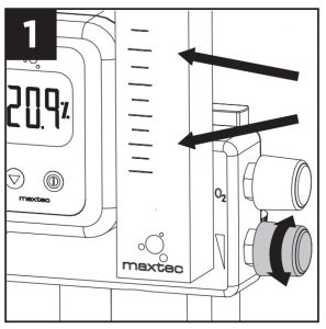
Room Air Calibration
CAUTION: Turn off all flow of gas to the MaxVenturi before calibration in room air.Calibrating the oxygen sensor in a gas concentration other than room air (20.9%) will result in an incorrect measurement of oxygen concentration.
- Shut off oxygen supply.
- Remove sensor from port.
- Wait two (2) minutes for sensor to equilibrate in room air
- Press and hold CAL button for three (3) seconds. Wait for display to read “20.9%”.
- Place sensor in port.


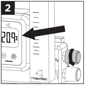
100% Oxygen Calibration
- Connect oxygen supply line from wall to MaxVenturi.
- Plug room air inlet.
- Turn ON/OFF valve to the ON position
- Turn flow knob a few turns to flow gas.
- Wait two (2) minutes for sensor to equilibrate.
- Press and hold CAL button for three (3) seconds. Wait for display to read 100%.
- Remove plug from room air inlet.
- Insert air inlet filter in room air inlet port.


NOTE: Analyzer will read “Cal Err St” if the sample gas is not stable or if the oxygen sensor has reached its end of life.
Device Set-up
NOTE: Patient circuit and patient interface should be assembled according to manufacturers instructions supplied with them.
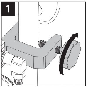
- Attach MaxVenturi to IV pole. Twist knob to tighten.
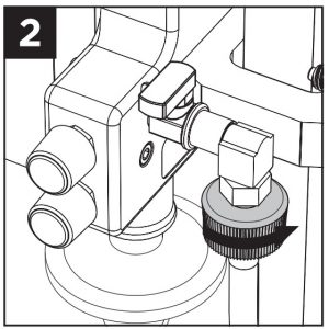
- Connect oxygen supply line from wall to MaxVenturi.
- Insert air inlet filter in room air inlet port.
- Attach patient circuit to MaxVenturi outlet.
- Turn ON/OFF valve to ON position.

Flow and Oxygen Settings Adjustment
Initial Settings
- Adjust flow to desired setting and read flow meter.
- Set desired oxygen mixture by opening O2% knob and read analyzer.
- Adjust flow if it has changed.
Changing Flow Settings
- Adjust flow to new desired flow rate.
- Readjust oxygen concentration to desired setting and wait for analyzer to equilibrate. Temporarily disconnect patient circuit if necessary.
Changing Oxygen Settings
- Adjust O2% knob to desired level and wait for analyzer to equilibrate.Temporarily disconnect patient circuit if necessary.
- Verify flow rate has not changed and adjust if necessary.

WARNING: Adjusting the oxygen setting too high at low flows may cause oxygen to exit the air inlet port. Verify the direction of flow by placing your hand under the air filter to feel for air escape
DisposablesThe MaxVenturi for is intended for use with approved disposables. Several patient delivery circuits and patient interfaces have been tested and approved for use with the MaxVenturi.The approved delivery circuits and patient interfaces are:
Disposable Patient Circuits
- Fisher & Paykel single heated limb circuit (RT202) with humidifier chamber (MR290).
- Airlife single heated limb circuit (RT600-850) with humidifier chamber (MR290).
- Comfort Flo® Circuits (2415 & 2416) with the ConchaSmart® Column (382-10).
Disposable Patient Interfaces
- Fisher and Paykel OptiflowTM+ Nasal Cannula – Large (OPT946).
- Fisher and Paykel OptiflowTM+ Nasal Cannula – Medium (OPT944).
- Fisher and Paykel OptiflowTM+ Tracheostomy (OPT970).
- Fisher and Paykel OptiflowTM+ Mask Interface Adapter (OPT980)
- Pediatric aerosol mask with 22mm inlet (Airlife 001263 or similar).Adult aerosol mask (Airlife 001206 or similar).
- Trach adaptor T-piece (Airlife 001500 or similar).
- Tracheostomy mask with 22mm inlet – loose fitting (Airlife 001225 or similar).
- Hudson RCI® Trach-Flex™ PlusTracheostomy Adapter (2415-01).
- Hudson RCI® Comfort Flo® Plus Cannula – Large (2412-11).
- Hudson RCI® Comfort Flo® Plus Cannula – Medium (2412-12).
- Hudson RCI® Comfort Flo® Plus Cannula – Small (2412-13).
CAUTION: Use of patient circuits or patient interfaces other than these constitutes “offlabel use”. This can result in device malfunction or harm to the patient.
The delivery circuit can be paired with the patient interface circuits listed in the table below:
TABLE INSTRUCTIONS: To determine the desired flow, locate the patient delivery circuit and interface in the two left-hand columns. Find the corresponding flow rate by reading to the right under columns A through F. The lettered columns correspond to the lettered graduations on the flow meter.
F&P Humidifier with 22mm Single Heated Limb Circuit
| INTERFACE PATIENT | A | B | C | D | E | F |
| Hudson RCI® Trach-Flex™ Plus Tracheostomy Adaptor (2415-01) | 7 | 21 | 31 | 41 | 49 | 57 |
| Hudson RCI® Comfort Flo® Plus Cannula – Large (2412-11) | 7 | 18 | 28 | 36 | 44 | 52 |
| Hudson RCI® Comfort Flo® Plus Cannula – Medium (2412-12) | 7 | 19 | 29 | 37 | 44 | 51 |
| Hudson RCI® Comfort Flo® Plus Cannula – Small (2412-13) | 7 | 17 | 26 | 34 | 41 | 48 |
| OptiflowTM+ Tracheostomy (OPT970) | 8 | 22 | 31 | 42 | 51 | 60 |
| OptiflowTM+ Nasal Cannula Large (OPT946) | 8 | 20 | 30 | 40 | 48 | 56 |
| OptiflowTM+ Nasal Cannula Medium (OPT944) | 8 | 18 | 28 | 37 | 45 | 53 |
| OptiflowTM+ Nasal Cannula Small (OPT942) | 7 | 16 | 23 | 31 | 38 | 46 |
| OptiflowTM+ Mask Interface Adapter (OPT980) | 7 | 22 | 32 | 43 | 52 | 61 |
Hudson RCI® Neptune®Heated Humidifier with ConchaSmart™ Technology and 15mm Comfort Flo Humidification Circuit (REF 2415 & 2416)
CAUTION: The flow rates listed in this table are the result of bench testing the MaxVenturi on the indicated patient circuits and interfaces. Actual flows may vary in clinical use depending on patients physiology, breathing rate and other factors listed in Section 3.0.
NOTE: For the Comfort Flo Humidification System, a section of 22mm tubing is used to connect the outlet of the MaxVenturi to the inlet of the humidification chamber in place of the supplied pressure relief valve.
FACTORS INFLUENCING ACCURATE READINGS
Elevation/Pressure Changes
- Changes in elevation result in a reading error of approximately 1% of reading per 250 feet.
- A change in altitude greater than 500 ft will require sensor recalibration.
- This device does not automatically compensate for changes in barometric pressure or altitude. If the device is moved to a location of a different altitude, it must be recalibrated before use (see section 2.2).
Temperature EffectsThe MaxVenturi will read correctly (within ±3%) when operating at thermal equilibrium within the operating temperature range of 15 °C – 40 °C (59 °F – 104 °F). The device must be thermally stable when calibrated and allowed to thermally stabilize after experiencing temperature changes before readings are accurate. For these reasons it is recommended to:
- Perform the calibration procedure at a temperature close to the temperature at which the device will be operated.
- Allow adequate time for the sensor to equilibrate to a new ambient temperature.
ATTENTION: “CAL Err St” may result from a sensor that has not reached thermal equilibrium
Humidity EffectThe MaxVenturi can be used in applications where the relative humidity of the sample gas ranges from 0 to 95%, non-condensing. However, it should be noted that water vapor exerts its own pressure in the same manner as oxygen does in a sample gas stream.
For example, if the analyzer is calibrated in dry gas and then the gas is humidified, the analyzer will correctly display a reading which is slightly lower than previously displayed. This is due to the dilution of oxygen in the sample gas by water vapor.
Additionally, gas streams of high humidity may tend to condense on the sensor. Condensation on the sensor may eventually affect performance. For this reason, it is recommended that the MaxVenturi be mounted so that the sensor is in a vertical position, facing downward to prevent condensate from flowing onto the sensing surface.
CALIBRATION ERRORS AND ERROR CODES
The analyzer has a self test feature built into the software to detect faulty calibrations, oxygen sensor failures, and low battery voltage. The tests and actions to take if an error occurs are:
E02: NO SENSOR ATTACHED
- sconnect the sensor and reconnect, making sure the male plug is fully inserted into the receptacle. The analyzer should now perform a new calibration with the error cleared.
- If the error still persists, remove the batteries, wait 30 seconds, then reinstall, to perform a factory reset and diagnostic on the analyzer. The analyzer should againperform a new calibration with the error cleared.
- Contact Maxtec Customer Service Department if the error code cannot be cleared.
E03: NO VALID CALIBRATION DATA AVAILABLE
- Make sure unit has reached thermal equilibrium.
- Perform calibration as described in this manual.
E04: BATTERY BELOW MINIMUM OPERATING VOLTAGE
- Replace batteries.
CAL ERR ST: O2 SENSOR READING NOT STABLE
- Wait for displayed oxygen reading to stabilize when calibrating the device at 100% oxygen.
- Wait for unit to reach thermal equilibrium. NOTE: this can take up to one half hour if the device is stored in temperatures outside the specified operating temperature range.
CAL ERR LO: SENSOR VOLTAGE TOO LOW
- Repeat calibration routine as described in this manual. If unit repeats this error more than three (3) times, contact Maxtec Customer Service
CAL ERR HI: SENSOR VOLTAGE TOO HIGH
- Repeat calibration routine as described in this manual. If unit repeats this error more than three (3) times, contact Maxtec Customer Service.
CAL ERR BAT: BATTERY VOLTAGE TOO LOW TO RECALIBRATE
- Replace batteries.
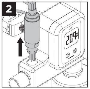
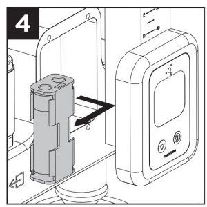
CHANGING THE OXYGEN SENSOR
- Turn off analyzer.
- Disconnect sensor from sensor cable.
- Remove sensor from sensor port. Dispose of sensor according to local guidelines.NOTE: For new sensor installation, follow procedure for new sensor installation in section 2.1.

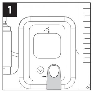
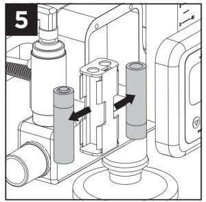
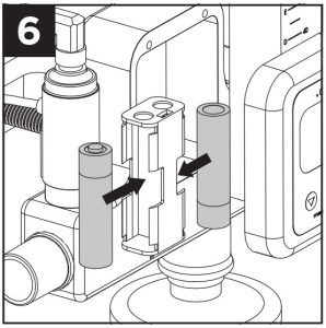
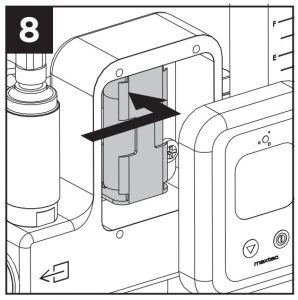
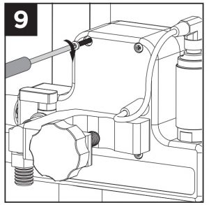
CHANGING THE BATTERIES
- Turn off analyzer.
- Use screwdriver to remove four (4) screws in back of device.
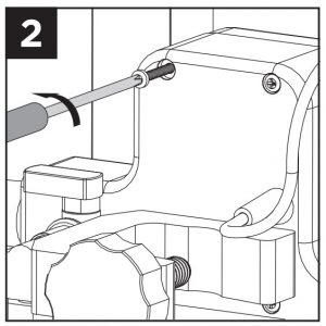
- Pull front cover off away from unit.
- Remove battery pack from rear wall of cavity. Use caution with wires.
- Remove two (2) depleted batteries.
- Ensure correct orientation and install two (2) new batteries.
- Turn on analyzer to verify power.
- Reattach battery pack to rear wall of cavity. Use caution to not pinch wires between cover and body of device.
- Re-attach front cover with four (4) screws.

CLEANING AND MAINTENANCE
Store the MaxVenturi at a temperature similar to that of its daily use.
Routine MaintenanceMaxtec recommends the performance check listed in the MaxVenturi Preventive Maintenance Manual be conducted prior to placing the MaxVenturi into clinical use and once a year thereafter.If the MaxVenturi does not function as described in the performance check, discontinue use of the device pending service by trained technicians or contact your Maxtec distributor or Maxtec at: 2305 South 1070 West Salt Lake City, Utah 84119.
Device CleaningWhen cleaning or disinfecting the exterior of the MaxVenturi, take appropriate care to prevent any solution from entering the device. Do not immerse device in fluids. MaxVenturi external surfaces may be cleaned using a cloth moistened with 65-70% isopropyl alcohol/water solution or a germicidal wipe.
Oxygen Sensor CleaningClean the sensor with a cloth moistened with 65-70% isopropyl alcohol/water solution.
- Maxtec does not recommend use of spray disinfectants because they can contain salts which can accumulate in the sensor membrane and impair readings.
- The oxygen sensor is not intended for steam, ethylene oxide or radiation sterilization.
SPECIFICATIONS
Analyzer Specifications
- Measurement Range ……………………………………0-100%
- Resolution…………………………..0.1%
- Accuracy and Linearity ……………..1% of full scale at constant temperature, R.H. and pressure when calibrated at full scale
- Total Accuracy ………±3% actual oxygen level over full operating temp range
- Response Time ………………….90% of final value in approximately 15 seconds at 23˚C
- Warm-up Time ………………………………………………………None required
- Operating Temperature ……………………………………..15˚C – 40˚C (59˚F – 104˚F)
- Storage Temperature …………………………………-15˚C – 50˚C (5˚F – 122˚F)
- Atmospheric Pressure ……………………….800-1013 mBars
- Humidity ……..0-95% (non-condensing)
- Power Requirements ………………2 AA Alkaline batteries (2 x 1.5 Volts)
- Battery Life ………….approximately 5000 hours with continuous use
- Low Battery Indication ………………….”BAT” icon displayed on LCD
- Sensor Type ………………Maxtec MAX-250 series galvanic fuel cell
- Expected Sensor Life ………… > 1,500,000 O2 percent hours minimum (2-year in typical medical applications)
- Dimensions ………………………..7.3 x 6.6 x 5.3 (185mm x 167mm x 135mm)
- Weight ………………………………2.54 ibs (1.15kg)
- Drift of Measurement …….< +/-1% of full scale at constant temperature, pressure and humidity
Oxygen Diluter Specifications
| FLOW ACCURACY | NOMINAL (LPM) | ACCURACY |
| 10 | ±33% | |
| Operating Range | 20 | ±18% |
| 30 | ±15% | |
| 40 | ±11% | |
| 50 | ±11% | |
| 60 | ±9% |
- FiO2 Range…………..32%-100%
- Oxygen inlet supply pressure ……..45-55 psig
- Oxygen inlet filter (internal) ………………….45-90 micron pore size
- Ambient air inlet filter ………Single patient use filter (see section 2.5 for appropriate filter details)
Oxygen Inlet SupplyThis device was designed for an oxygen inlet pressure of 3.5 bar (50psi). Certain geographical areas use 4 bar (58psi) or 5bar (73psi) as the standard piped oxygen distribution pressure. This device can be operated at these pressures but the flow readings on the flow meter must be corrected for the additional pressure. The table below gives correction factors for each flow meter graduation indicating the percent increase in flow from nominal that will result due to the increased inlet pressure at 4bar and 5bar.
| NOMINAL FLOW LPM | 4 BAR (% INCREASE) | 5 BAR (% INCREASE) |
| 10 – A | 13 | 34 |
| 20 – B | 9 | 24 |
| 30 -C | 7 | 18 |
| 40 -D | 6 | 16 |
| 50 – E | 5 | 13 |
| 60 -F | 4 | 12 |
MAXVENTURI SPARE PARTS AND ACCESSORIES
Included With Your Unit
| PART NUMBER | ITEM |
| R211M03 | Operating Manual & Instructions for Use |
| R125P03-002 | MAX-250E Oxygen Sensor |
| RP34P02 | Air inlet filter |
| R211P38 | Muffler, Venturi |
Standard Replacement Parts & Accessories
| PART NUMBER | ITEM |
| R127P35 | 15’ coiled polyurethane oxygen hose with DISS ends. |
| R100P41 | Locking Pole Clamp Bracket |
| R100P44 | Pole/Rail Mount Bracket |
Other Replacement Parts and RepairsFor repair or parts issues not specified in this manual refer to the MaxVenturi Service Manual (R211M01), or the MaxVenturi Preventative Maintenance Manual (R211M02).
Preventative MaintenanceIt is recommended by Maxtec that service personnel check the function of the device once a year, or as needed. It is also recommended that the MaxVenturi’s flow and O2 adjustment valves be replaced a minimum of every 4 years with R211P30-001 and R211P30-002 to replaceall O-rings, valves, and knobs. The MaxVenturi Preventative Maintenance Manual will guide you through these processes. It is available for free at www.maxtec.com. Equipment in needof factory repair shall be sent to:
MaxtecCustomer Service Department2305 South 1070 WestSalt Lake City, Utah 84119(Include RMA number)
TROUBLESHOOTING
PROBLEM: The flow does not reach 55LPM even with the flow valve wide open.
- Possible Cause: The pressure of your piped oxygen supply in your hospital may be low. Also check to see if the float in the flow meter is sticking. Tip the unit back And forth. Ball should roll freely. If it seems to stick or hesitate, return the unit to Maxtec for service. If you cannot detect the problem, contact the Maxtec Service Department by calling the number listed in this manual. Do not disassemble the device to try to detect an internal problem.
PROBLEM: The oxygen level on the display does not reach 100%, even with the oxygen control knob fully open.
- Possible Cause: Check if the device needs to be calibrated. If you wish to use the device at oxygen concentrations closer to 100% oxygen, it is best to calibrate the device at 100% oxygen. Refer to the calibration section in this manual and follow the 100% oxygen calibration routine. If this does not solve the problem, contact the Maxtec Service Department.
PROBLEM: The oxygen level displayed does not go as low as the level indicated in the specifications, even with the oxygen control knob completely closed.
- Possible Cause: It is very likely the device needs to be calibrated. Also check to make sure the humidifier and patient delivery disposables are the correct size and installed correctly with no kinking or occlusion. Check the air inlet filter for moisture or dirt – replace if necessary. Valve cartridges may be worn; perform leak testaccordin g to preventative maintenance procedure.
AIR-ENTRAINMENT DEVICES VS BLENDERS
There are basic differences in the operation of a venturi air-entrainment device, such as the MaxVenturi, versus an air oxygen blender. Some of the differences are listed in the chart below. Further information regarding the use of these types of devices can be found in literature such as: R. Wilkins et. al, Egan’s Fundamentals of Respiratory Care, St. Louis: Mosby, 2003. Maxtec recognizes that the condition of the patient should be the primary factor in deciding which type of treatment is suitable for use.
| MAXVENTURI | AIR-OXYGEN BLENDER |
| FiO2 Range: 32-100% | FiO2 Range: 21-100% |
| No low pressure gas alarms | Audible alarm for low gas pressure or differential gas pressure |
| Flow is compliant to downstream flow resistance | Flow is less compliant to downstream flow resistance |
| Requires only an oxygen supply | Requires both oxygen and medical air supply |
| Flow: 0-60 LPM | Flow: 0-120 LPM |
| Requires large bore tubing | Supports any size tubing |
ELECTROMAGNETIC COMPATABILITY
The information contained in this section (such as separation distances) is in general specifically written with regard to the MaxVenturi. The numbers provided will not guarantee faultless operation but should provide reasonable assurance of such. This information may notbe appli cable to other medical electrical equipment; older equipment may be particularly susceptible to interference.
NOTE: Medical electrical equipment requires special precautions regarding electromagnetic compatibility (EMC) and needs to be installed and put into service according to the EMC information provided in this document and the remainder of the instructions for use this device. Portable and mobile RF communications equipment can affect medical electrical equipment. Cables and accessories not specified within the instructions for use are not authorized. Using other cables and/or accessories may adversely impact safety, performance and electromagnetic compatibility (increased emission and decreased immunity).
Care should be taken if the equipment is used adjacent to or stacked with other equipment; if adjacent or stacked use is inevitable, the equipment should be observed to verify normal operation in the configuration in which it will be used.
| ELECTROMAGNETIC EMISSIONS | ||
| This equipment is intended for use in the electromagnetic environment specified below. The user of this equipment should assure that it is used in such an environment. | ||
| EMISSIONS | COMPLIANCE ACCORDING TO | ELECTROMAGNETIC ENVIRONMENT |
| RF Emissions (CISPR 11) | Group 1 | The MaxVenturi uses RF energy only for its internal function. Therefore, its RF emissions are very low and are not likely to cause any interference in nearby electronic equipment. |
| CISPR Emissions Classification | Class A | The MaxVenturi is suitable for use in all establishments other than domestic and those directly connected to the public low- voltage power supply network that supplies buildings used for domestic purposes.
NOTE: The EMISSIONS characteristics of this equipment make it suitable for use in industrial areas and hospitals (CISPR 11 class A). If it is used in a residential environment (for which CISPR 11 class B is normally required) this equipment might not offer adequate protection to radio-frequency communication services. The user might need to take mitigation measures, such as relocating or re-orienting the equipment. |
| Harmonic Emissions (IEC 61000-3-2) | Class A | |
| Voltage Fluctuations | Complies |
| ELECTROMAGNETIC IMMUNITY | ||
| This equipment is intended for use in the electromagnetic environment specified below. The user of this equipment should assure that it is used in such an environment. | ||
| IMMUNITY AGAINST | IEC 60601-1-2: (4TH EDITION) TEST LEVEL | ELECTROMAGNETIC ENVIRONMENT |
| Professional Healthcare Facility Environment | Home Healthcare Environment | |
| Electrostatic discharge, ESD (IEC 61000-4-2) | Contact discharge: ±8 kV Air discharge: ±2 kV, ±4
kV, ±8 kV, ±15 kV |
Floors should be wood, concrete, or ceramic tile. If floors are covered with synthetic material, the relative humidity should be kept at levels to reduce electrostatic charge to suitable levels.
Mains power quality should be that of a typical commercial or hospital environment. Equipment which emits high levels of power line magnetic fields (in excess of 30A/m) should be kept at a distance to reduce the likelihood of interference. If user requires continued operation during power mains interruptions, ensure that batteries are installed and charged. Ensure that battery life exceeds longest anticipated power outages or provide an additional uninterruptible power source. |
| Electrical fast transients / bursts (IEC 61000-4-4) | Power supply lines: ±2 kV
Longer input / output lines: ±1 kV |
|
| Surges on AC mains lines (IEC 61000-4-5) | Common mode: ±2 kV Diferential mode: ±1 kV | |
| 3 A/m power frequency magnetic field 50/60 Hz (IEC
61000-4-8) |
30 A/m
50 Hz or 60 Hz |
|
| Voltage dips and short interruptions on AC mains
input lines (IEC 61000-4-11) |
Dip>95%, 0.5 periods
Dip 60%, 5 periods Dip 30%, 25 periods Dip >95%, 5 seconds |
| Recommended separation distances between portable and mobile RF communications equipment and the equipment | |||
| RATED MAXIMUM OUTPUT POWER OF TRANSMITTER
W |
Separation distance according to frequency of transmitters in meters | ||
| 150 kHz to 80 MHz d=1.2/V1] ÖP | 80 MHz to 800 MHz d=1.2/V1] ÖP | 800MHz to 2.5 GHz d=2.3 ÖP | |
| 0.01 | 0.12 | 0.12 | 0.23 |
| 0.1 | 0.38 | 0.38 | 0.73 |
| 1 | 1.2 | 1.2 | 2.3 |
| 10 | 3.8 | 3.8 | 7.3 |
| 100 | 12 | 12 | 23 |
| For transmitters rated at a maximum output power not listed above, the recommended separation distance d in meters (m) can be estimated using the equation applicable to the frequency of the transmitter, where P is the maximum output power rating of the transmitter in watts (W) according to the transmitter manufacturer.
NOTE 1: At 80 MHz and 800 MHz, the separation distance for the higher frequency range applies. NOTE 2: These guidelines may not apply in all situations. Electromagnetic propogation is affected by absorption and reflection from structures, objects, and people. |
| This equipment is intended for use in the electromagnetic environment specified below. The customer or the user of this equipment should assure that it is used in such an environment. | |||
| IMMUNITY TEST | IEC 60601-1-2: 2014 (4TH EDITION) TEST LEVEL | ELECTROMAGNETIC ENVIRONMENT – GUIDANCE | |
| Professional Healthcare Facility Environment | Home Healthcare Environment | ||
| Conducted RF coupled into lines (IEC 61000-4-6) | 3V (0.15 – 80 MHz)
6V (ISM bands) |
3V (0.15 – 80 MHz)
6V (ISM & Amateur bands) |
Portable and mobile RF communications equipment (including cables) should be used no closer to any part of the equipment than the recommended separation distance calculated from the equation applicable to the frequency of the transmitter as below. Recommended sparation distance:
d=1.2 ÖP d=1.2 ÖP 80 MHz to 800 MHz d=2.3 ÖP 800 MHz to 2.7 GHz Where P is the maximum output power rating of the transmitter in watts (W) according to the transmitter manufacturer and d is the recommended separation distance in metres (m). Field strengths from fixed RF transmitters, as determined by an electromagnetic site survey a, should be less than the compliance level in each frequency range b. Interference may occur in the vicinity of equipment marked with the following symbol:
|
| Radiated RF immunity (IEC 61000-4-3) | 3 V/m
80 MHz – 2.7 GHz 80% @ 1 KHz AM Modulation |
10 V/m
80 MHz – 2.7 GHz 80% @ 1 KHz AM Modulation |
The ISM (industrial, scientific and medical) bands between 150 kHz and 80 MHz are 6,765 MHz to 6,795 MHz; 13,553 MHz to 13,567 MHz; 26,957 MHz to 27,283 MHz; and 40,66 MHz to 40,70 MHz.
Field strengths from fixed transmitters, such as base stations for radio (cellular/cordless) telephones and land mobile radios, amateur radio, AM and FM radio broadcast and TV broadcast cannot be predicted theoretically with accuracy. To assess the electromagnetic environment due to fixed RF transmitters, an electromagnetic site survey should be considered. If the measured field strength in the location in which the equipment is used exceeds the applicable RF compliance level above, the equipment should be observed to verify normal operation. If abnormal performance is observed, additional measures may be necessary, such as reorienting or relocating the equipment.
contact us
2305 South 1070 WestSalt Lake City, Utah 84119(800) 748-5355www.maxtec.com
References
[xyz-ips snippet=”download-snippet”]