![]() DFB FlowmetersDESIGNED FOR BLENDERS, DUAL TAPERInstructions for Use
DFB FlowmetersDESIGNED FOR BLENDERS, DUAL TAPERInstructions for Use

R219M01 REV. C
![]() Maxtec2305 South 1070 WestSalt Lake City, Utah 84119 USA
Maxtec2305 South 1070 WestSalt Lake City, Utah 84119 USA
phone: (800) 748.5355fax: (801) 973.6090email: [email protected]web: www.maxtec.com
![]()
WARRANTY
Under normal operating conditions, Maxtec warrants the Acrylic Flowmeters to be free fromdefects of workmanship or materials for the following period:a) Acrylic Housing ………………………………………………………………………………. A lifetime of the productb) Needle Valve ……………………………………………………………………………. Five (5) years from receiptc) All other parts not listed ……………………………………………………………. Two (2) years from receiptWarranty does not cover breakage/abuse.These warranties are from the date of receipt, provided that the product is properly operated and maintained in accordance with Aztec’s operating instructions. based on Maxtecproduct evaluation, Maxtec’s sole obligation under the foregoing warranty is limited to making replacements, repairs, or issuing credit for equipment found to be defective. This warranty extends only to the buyer purchasing the equipment directly from Maxtec or through Maxtec’s designated distributors and agents as new equipment. Routine maintenance items, such as o-rings, are excluded from the warranty. Maxtec and any other subsidiaries shall not be liable to the purchaser or other persons for incidental or consequential damages or equipment that has been subject to abuse, misuse, misapplication, alteration, negligence, or accident. These warranties are exclusive and in lieu ofall other warranties, expressed or implied, including the warranty of merchantability and fitness for a particular purpose. For product warranty returns, please contact Maxtec Customer Service for a Returned Materials Authorization (RMA). WARNINGS◆ This manual instructs a professional to install and operate the flowmeter. This is provided for your safety and to prevent damage to the flowmeter. If you do not understand this manual,DO NOT USE the flowmeter and contact your provider.◆ Use flowmeters only for their “Intended Use” as described in this manual.◆ ALWAYS confirm prescribed flow before administering to patient and monitor flow on a frequent basis.◆ Flowmeters may contain magnetic, ferrous material that may affect the results of an MRI.◆ Read this User Manual before installing or operating the flowmeter.To Reduce the Risk of Fire or Explosion:◆ ALWAYS follow ANSI and CGA standards for Medical Gas Products and flowmeters and Oxygen Handling.
![]() DO NOT use or store oils, greases, organic lubricants or any combustible materials on or near this flowmeter.
DO NOT use or store oils, greases, organic lubricants or any combustible materials on or near this flowmeter.![]() DO NOT use near any type of flame or flammable/explosive substances, vapors or atmosphere.
DO NOT use near any type of flame or flammable/explosive substances, vapors or atmosphere.![]() DO NOT connect to source pressure greater than 100 psi.
DO NOT connect to source pressure greater than 100 psi.![]() DO NOT disassemble the flowmeter while pressurized.
DO NOT disassemble the flowmeter while pressurized.![]() DO NOT smoke in an area where oxygen is being administered.
DO NOT smoke in an area where oxygen is being administered.![]() CAUTIONS◆ Use caution to avoid cross-threading fittings during installation.◆ Always use a backing wrench when installing or removing connectors.◆ Flowmeters must be operated with the Flow Tube in a vertical, upright position.◆ Only personnel instructed and trained in its use should operate this flowmeter.◆ Ensure all connections are tight and leak-free.◆ Only use an oxygen-safe leak detector.◆ Only trained medical professionals should operate the flowmeter.
CAUTIONS◆ Use caution to avoid cross-threading fittings during installation.◆ Always use a backing wrench when installing or removing connectors.◆ Flowmeters must be operated with the Flow Tube in a vertical, upright position.◆ Only personnel instructed and trained in its use should operate this flowmeter.◆ Ensure all connections are tight and leak-free.◆ Only use an oxygen-safe leak detector.◆ Only trained medical professionals should operate the flowmeter.![]() DO NOT drop the flowmeter.
DO NOT drop the flowmeter.![]() DO NOT autoclave.
DO NOT autoclave.![]() DO NOT gas sterilize with EtO (Ethylene Oxide).
DO NOT gas sterilize with EtO (Ethylene Oxide).![]() DO NOT clean with aromatic hydrocarbons.
DO NOT clean with aromatic hydrocarbons.![]() DO NOT immerse the flowmeter in any kind of liquid. This will void the warranty.
DO NOT immerse the flowmeter in any kind of liquid. This will void the warranty.![]() DO NOT use if damaged. Inspect the flowmeter for visual damage before each use.
DO NOT use if damaged. Inspect the flowmeter for visual damage before each use.![]() DO NOT over-tighten the knob when turning it off. This will cause damage to the flowmeter.
DO NOT over-tighten the knob when turning it off. This will cause damage to the flowmeter.![]() DO NOT over-tighten any threaded connectors; the body may crack and cause leaks.◆ The flowmeter has been specifically calibrated for use on the outlet of an air/oxygen blender. The accuracy of the flow rates will be affected if the flowmeter is used in any other way◆ Gas temperatures other than 70° F (21°C) may affect the accuracy of the indicated flow.◆ Attaching accessories to the outlet (which may increase resistance to outlet flow) may change the indicated flow but will not affect the accuracy of the flow.
DO NOT over-tighten any threaded connectors; the body may crack and cause leaks.◆ The flowmeter has been specifically calibrated for use on the outlet of an air/oxygen blender. The accuracy of the flow rates will be affected if the flowmeter is used in any other way◆ Gas temperatures other than 70° F (21°C) may affect the accuracy of the indicated flow.◆ Attaching accessories to the outlet (which may increase resistance to outlet flow) may change the indicated flow but will not affect the accuracy of the flow.
Symbol Guide

PRODUCT OVERVIEW
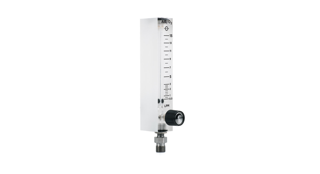
DescriptionMaxtec DFB flowmeters are designed and calibrated to provide increased accuracy compared to standard flowmeters when used on-air/oxygen blender outlets. By utilizing dual-scale graduations, the flowmeters provide two flowmeters in one for increased accuracy at lower flows. The flowmeters feature high-quality acrylic block bodies and precision valves. Each flowmeter comes equipped with a DISS outlet and DISS adapter for neat and compact attachment to the side of the blender.Intended useThe flowmeter is intended for use as a secondary flowmeter for an air/oxygen blender, such as the Maxtec MaxBlend 2, and is to be used by physicians, respiratory therapists nd other authorize ed hospital personnel to administer selected doses of medical gases to a patient.
SPECIFICATIONS
Flow Range Accuracy Chart
| MODEL | FLOW | GRADUATIONS | ACCURACY |
| R219P99-400 | 0-3 LPM | 0. 1 (0.1-1) LPM0.5 (1-3) [PM | ± 0.5 PM |
| R219P79-400 | 0-15 LPM | 0.25 (0.5-3) LPM1(5-15) LPM | 0.5-3: ± 0.5 LPM5-15: ± 10% of indicated value |
| R2I9P88-400 | 0-30 LPM | 0.25 (0.5-3) LPM2.5 (5-30) LPM | 0.5-3: ± 0.5 LPM5-30: ± 10% of indicated value |
| R219P87-400 | 0-70 LPM | 1(2-15) LPM5 (15-70) LPM | 2-4: ± 0.5 LPM5-70: ± 10% of indicated value |
Transport/Storage Requirements
-40 °F (-40 °C) to 140 °F (60 °C)NOTE: Storage/transport outside the specified range may cause damage to the flowmeter.The above flowmeter models are calibrated for air/oxygen blenders at 70°F (21°C) and standard atmospheric pressure with inlet pressures at 50 PSI and 60% O₂. Specificationsare subject to change without prior notice.
OPERATING INSTRUCTIONS
General Operation
- Remove the air and oxygen line pressure to the air/oxygen blender and ensure the valve to the flowmeter is closed.
- Apply a thread sealant that is appropriate for medical oxygen use to the male NPT thread of the supplied 90 degrees NPT to the DISS adapter.
- Use a backing wrench to secure the female NPT fitting on the back of the flowmeter while hand-tightening the male NPT thread of the 90 degrees NPT to DISS adapter into the female NPT fitting.
- With the backing wrench still in place, tighten the 90 degrees NPT to DISS adapter fitting at least one full revolution. Continue to tighten the fitting until it is aligned properly for the desired attachment configuration on the air/oxygen blender output.
- Attach the flowmeter to the air/oxygen blender output using the DISS connection. The flowmeter must be mounted vertically for accurate measurements.
- Restore pressure to the air/oxygen blender and verify that the float ball is at the very bottom of the flow tube.
- NOTE: If the float is not resting at the bottom of the flow tube, the product is leaking; consult the “TROUBLESHOOTING” Section 4.0.
- Adjust flow:To increase- Turn the knob counterclockwiseTo decrease- turn the knob clockwise
- Set the flow by aligning the center of the float ball with the indicator lines on the flow tube. Adjusting flow beyond the last calibrated indicator line will result in an undetermined flow.
TROUBLESHOOTING
Troubleshooting Table
| PROBLEM | CAUSE | REMEDY |
| Will not shut off | Leak Defective valve | Consult your provider or Maxtec |
| Sticking float ball or unableto set the desired flow | Debris in flow tube | |
| The knob will not turn | Valve seized |
RECOMMENDED MAINTENANCE
Cleaning Instructions
- Depressurize and disconnect all connections before cleaning.
- Clean exterior surfaces of the flowmeter with a cloth dampened with a mild detergent and water.
- Wipe dry with a clean cloth.
![]() CAUTION: Do Not Autoclave
CAUTION: Do Not Autoclave![]()
2305 South 1070 West Salt Lake City, Utah 84119(800) 748-5355www.maxtec.com
References
[xyz-ips snippet=”download-snippet”]