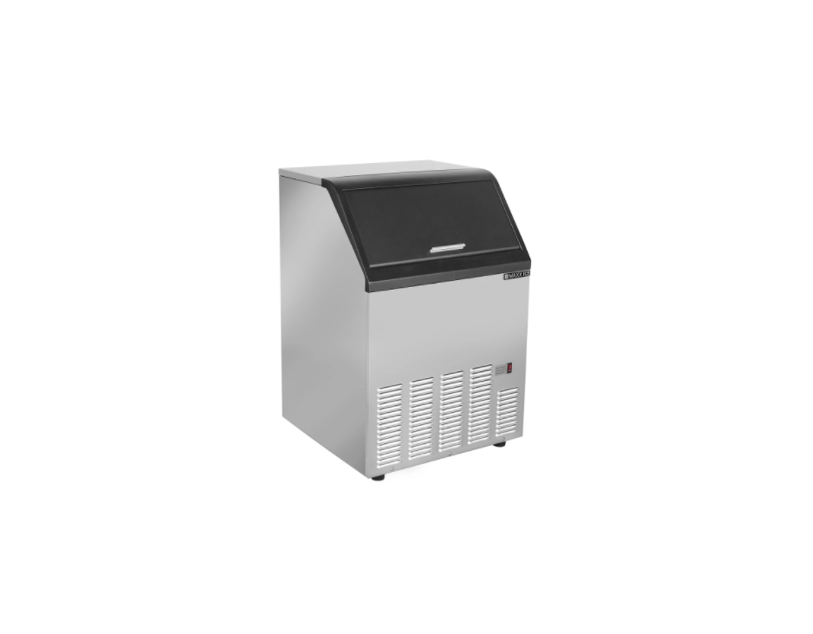
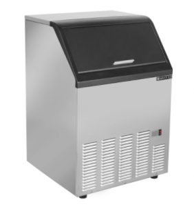
MAXX ICE MID200 Ice Dispenser Installation Guide
Safety Warnings and Information
Special attention should be given to potential hazard labeling on the equipment and the signal words and symbols that are used throughout this manual. They may also be used to alert against unsafe practices.
 WARNING: Indicates a potentially hazardous situation that may result in serious injury or death.CAUTION: Indicates a potentially hazardous situation that may result in personal injury. The situation may also result in equipment or property damage.
Note: Indicates installation, operation, or maintenance information which is important, but not related to personal injury or property damage.Note: Check for freight damage before proceeding with the equipment installation. Be sure to inspect the equipment carefully for any damage that may not have been evident on the outside of the carton. Contact the freight carrier immediately to report any damage and file a claim. Have carrier note the damage on the bill of lading. Call Maxx Cold with your claim number to arrange replacement or repair.
- Read the entire manual before installing, operating or servicing the machine.
- Follow these installation instructions exactly.
- All machines have been tested and adjusted for correct performance at the factory.
- Knowledge of proper installation and service procedures is essential for the safe operation and maintenance of MAXX ICE equipment. Refer all installation and service work to qualified technicians.
- This equipment must be installed in compliance with the applicable federal, state/province, and/or local plumbing, electrical, and health/sanitation codes and requirements.
- Always disconnect the power supply before servicing the equipment or when the equipment will not be used for a period of time.
- Never operate equipment that has been damaged or does not have all the protective covers in place.
- Never operate equipment that has been altered from the original MAXX ICE specifications
WARNING: Use only genuine MAXX ICE replacement parts, Use of non-approved parts when servicing MAXX ICE equipment may create a safety hazard, cause equipment damage, property damage and will void the warranty.
Ice Dispenser Identification Model Number Key
Standard Series
MID 200 Hotel Dispenser 115V 60HZ 1PHMID 200 (F0) Hotel Dispenser 208-230 60HZ 1PHMID 200 (E0) Hotel Dispenser 220-240 50HZ 1PH
X Series
MIDX 200 Hotel Dispenser 115V 60HZ 1PHMIDX 200 (F0) Hotel Dispenser 208-230 60HZ 1PHMIDX 200 (E0) Hotel Dispenser 220-240 50HZ 1PH
Note: The serial number plate is located behind the front cover, on the upper support. A complete model number and date code are essential for the accurate identification of the ice dispenser and proper selection of replacement parts.
WARNING:
- Instruct all personnel in the proper use of the equipment.
- Clean up any liquid spills immediately
Unpacking
Unpacking the ice dispenser can be done by cutting the bands that are holding the cardboard box to the shipping pallet. The box can then be lifted vertically to expose the machine.Remove all packaging materials from the ice dispenser and protective film from the stainless steel surfaces.
Carton Contents
- Maxx Ice MID200 Series Ice Dispenser
- Leg kit.
- Installation & Operation Manual. Leave these with the owner/user.
- Ice machine mounting hardware, gasket and wiring components for thermostat connection.
Installation Requirements
The ice dispenser must be installed indoors. Do not install the dispenser in an unprotected outdoor area or any wet area.Note:Consult ice machine instructions for proper installation requirements, before determining the location of the ice dispenser.Installation site ambient temperatures below 90°F (32°C) are recommended for proper operation. Higher than this maximum specification will result in increased melting of ice in the dispenser. Also avoid areas near a heat source or in direct sunlight.
- The location must not be near anything that can contaminate the dispenser and/or the ice inside.
- The location must not be in an area subject to corrosive elements.
- The ice dispenser should be mounted on the legs provided and leveled by screwing the leg adjusters in or out as required. If the legs are not used, shim the bottom of the dispenser as required to make it level. Seal any gaps at the floor with approved sealant or use cove molding for larger gaps.
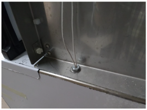
- The installation location must have a stable and level surface capable of supporting the weight of the ice machine and dispenser, with a full bin of ice. After locating the dispenser, apply the gasket provided and position the ice machine with its back flush with the back of the dispenser.
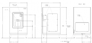
Align the two ice machine mounting holes with the forward fasteners in the top of the dispenser side walls. Attach the ice machine with the two hollow bolts and washers provided
Plumbing
- The drain hose or pipe must not be reduced in size from the equipment to the drain. The building drain must be able to accommodate all the drain water from ice making and storage.
- Individual drains from ice machines, dispensers and bins must never be directly connected to a common manifold, drain or standpipe unless a minimum 1.5” (38mm) air gap is provided at each connection. This is to prevent backflow of drain water into the ice maker, dispenser or ice bin.Note: Installation must always provide adequate backflow prevention and comply with applicable federal, state and local codes.Drain lines will be installed with a minimum drop of 1/4” per ft. (2.1cm per meter) run. Drain lines may be insulated to prevent condensation.
Electrical
WARNING: Failure to comply with these regulations may cause serious injury or death and cause damage to the machine and its surroundings.WARNING: Always disconnect power before servicing.
- All models are intended to be installed with a permanent connection to the field electrical supply. See rating plate on the back of the machine for power supply requirements.
- The dispenser must be connected to a separate protected circuit with no other loads.
- Fused disconnects, installed adjacent to the dispenser, are recommended and may be required by local codes. These components must be supplied by the installer.
- Electrical service must fall within the voltage tolerances listed below:
| Model | Nominal (V) | No-Load Maximum | Full-Load Minimum |
| MID201 | 115 | 126 | 104 |
| MID204 | 208-230 | 250 | 198 |
Maximum Overload Protection must be no greater than specified. The minimum circuit ampacity specified does not indicate a typical running current value. Use the minimum ampacity value for sizing branch circuit conductors up to 26 feet (8 meters) in length. For a conductor length over this length, increase the wire gauge as required by code.
Note: The MID200 dispenser has a bin thermostat in place for use when the dispenser is combined with a curtain switch controlled ice machine. This thermostat must be wired in series with the ice machine curtain switch to maintain the proper ice level in the bin. If this is not done, the bin may overfill and cause damage to the dispenser and ice machine. See additional instructions for this connection.
- Remove the large access cover on the right side of the dispenser.
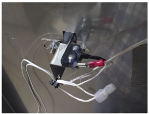
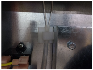
- With the right side ice machine panel removed, locate, cut and remove the wire tie on the bracket near the curtain switch.
- Remove the wire from the common terminal of the switch, cut the terminal connector from this wire and strip the end of the wire .300”.
- Using the wire assembly provided with the dispenser, slip the red insulated connector on the common terminal of the curtain switch. Join the end of the other wire provided with the wire removed from the curtain switch and apply the closed end connector provided.
- Secure these wires to the bracket near the curtain switch with the wire tie provided.
- Run the wire ends down to and through the hollow bolt into the ice dispenser.
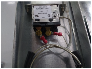
- Insert the wire ends into the top end of the plastic tube, next to the dispenser controls, and push the wires through the tube down to the bin thermostat switch.
- Attach the two spring spade connectors to the wire ends and attach the wires to the switch.
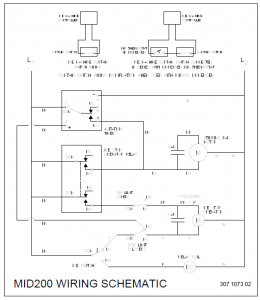
Wiring Diagram
Dispenser Construction and Operation
The MID200 series dispenser consists of an ice storage bin with an outlet spout, a motorized stirring bar to keep the ice from bridging in the bin and to move ice to the outlet spout when dispensing and an operating ice stop in the spout opening to deflect ice past the spout during agitation cycles and allow ice out when dispensing. Working in conjunction with the ice stop, an ice outlet cover seals the opening of the ice spout when the unit is not dispensing.A sink with a space to locate an ice bucket is provided on the front of the dispenser. The sink platform has openings to allow any missed or overflow ice to pass through to a catch pan, which is located at the bottom of the dispenser. The pan also catches the melt water from the ice bin and directs it to the drain.Note: The dispenser must be operational when the ice machine is in place and begins to make ice. Allowing the dispenser bin to fill with ice, without the dispenser being operational, may cause damage to the dispenser. The dispenser must also be operational whenever there is ice in the bin, even if the ice machine is not operating. If the dispenser must be disconnected from the power source for more than a short time, the bin should be emptied first.In normal operation, when power is initially provided to the dispenser, the stirring bar will turn for a few seconds. This is the initial agitation cycle and it will repeat periodically to keep the ice moving and fluid in the bin, when ice is not being dispensed. A timer determines the length of the agitation cycle, as well as the time between cycles. This will continue as long as the dispenser is energized.Pushing the ice button will cause the stirring bar to turn and the ice stop to open. Ice will then be directed to the sink area.Note: Dispensing should never occur without an ice bucket or other suitable vessel in position to catch the ice.
Adjustments
There are three adjustments available on the dispenser. One is for the limit switches that determine the movement range of the ice stop. The bin thermostat can also be adjusted to turn off the ice machine when ice contacts it. Chain tension is also adjustable. These are set at the factory and should not normally require attention unless parts are replaced or damaged.
Deflector Installation
An ice deflector has been provided for installation on the inner right side of the ice machine and must be used to keep ice and water off the right side wall of the dispenser. The deflector is shipped upside down, attached on the right side wall of the dispenser. Remove the deflector and reinstall right side up after the ice machine is in position. See photo below. The deflector must be slipped behind the right end of the water trough and pushed back tight to the wall.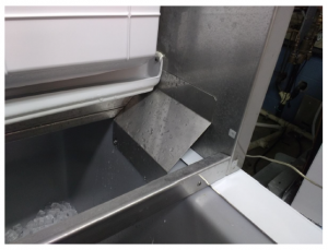
Maintenance and Service Information
Ice Dispenser Cleaning ProcedureIt is recommended to perform this cleaning procedure a minimum of twice per year
Note: The frequency of the need for cleaning is determined by the supply water characteristics. The dispenser should be cleaned no less than once every 6 months and it may require more frequent cleaning. The requirement for sanitizing frequency may be described in local health code regulations. Remove all ice from the dispenser before starting the cleaning process. Always clean the ice machine first, following the ice machine cleaning instructions.
- Empty the dispenser and disconnect the power to the dispenser and ice machine.
- Remove the ice machine skin panels, drain pan, chute and deflectors, if present.
- Wash the interior of the bin with a solution of 2 tablespoons of baking soda per quart of clean water (140°F / 60°C max.). The bin is accessed through the front of the ice machine. Use a long handled brush to reach the bottom of the bin and to clean the stirring bar.
- Wash the interior of the sink with the baking soda solution and wipe dry with a clean cloth.
- Remove the front cover of the dispenser to access the spout and drain pan. The spout should be removed for thorough cleaning in the baking soda solution. Rinse with clean water. Wash the interior of the drain pan with the baking soda solution and wipe dry with a clean cloth
- Sanitize all ice contact surfaces, including the ice spout and spout closure with a solution of 1 teaspoon of 5-1/4% sodium hypochlorite (household bleach) per quart of clean water (minimum 100 PPM free chlorine). A spray bottle will facilitate this process. Pour the unused sanitizing solution down the dispenser bin drain.
- Replace the ice spout, dispenser front panel and ice machine skin panels before reconnecting the power supply. Exterior surfaces may be cleaned by using standard methods suitable for stainless steel.
Storage and Winterization
Remove all ice from the dispenser, disconnect the electric power supply and clean and sanitize the dispenser.
Removal from service
When the ice dispenser is determined to be no longer useable, please be sure that it is rendered safe for storage or disposal. All applicable recycling measures should be exercised to avoid injury or harm to the environment. Neither the manufacturer nor seller is responsible for any harm or damage to people, animals, property or the environment caused by improper installation or disposal.
Problems and Solutions
| PROBLEM | POSSIBLE CAUSE | SOLUTION |
| Dispenser not operating | No Power to Dispenser | Reset Circuit Breaker or Replace Fuse |
|
Agitation Motor Does Not Turn |
If the Agitation Motor Does Not Turn for a Few Seconds at the Initiation of Power to the Dispenser or Periodically Thereafter, But Does Turn When the Ice Button is Pushed, the Agitation Timer May be Defective |
Replace Agitation Timer |
| If the Agitation Motor Does Not Turn When the Ice Button is Pushed, but Does Turn for a Few Seconds at the Initiation of Power to the Dispenser, the Ice Button or the Relay May be
Defective. |
Replace Ice Button or Relay |
|
| If Agitation Motor Does Not Turn at Application of Power, or When Ice Button is Pushed, the Agitation Motor or Motor Capacitor May be Defective |
Replace Agitation Motor or Capacitor |
|
|
Agitation Motor is Energized, but is Stuck and Cannot Turn. Periodic Agitation May Not be Occurring |
Disconnect and Reconnect Power to the Dispenser. If Motor Does Not Energize for a Few Seconds at Application of Power, Replace
Agitation Timer |
|
| Agitation Motor Continues to Turn for More Than a Few Seconds after the Ice Button is Released |
Ice Button May be Stuck or Defective. Relay May be Defective. |
Unstick or Replace Ice Button, or Replace Relay as Required |
|
Ice Stop Does Not Open When Ice Button is Pushed. |
Ice Stop Operator, Operator Capacitor, Relay or Limit Switch May be Defective. Ice Stop Linkage May be Damaged. | Check and Replace Operator, Capacitor, Relay, Limit Switch or Linkage as Required. |
|
Ice Stop Does Not Close When Ice Button is Released. |
Ice Stop Operator, Operator Capacitor or Limit Switch May be Defective. Ice Stop Linkage May be Damaged. | Check and Replace Operator, Capacitor, Limit Switch or Linkage as Required. |
DISPENSER PARTS LIST
| 302143201 | HD200 FRONT COVER | 511119601 | HD200 DRIVE BEARING |
| 302141801 | HD200 TOP CAP | 302141701 | HDX200 FRONT COVER |
| 301185701 | HD200 REAR COVER | 207100101 | HD200 STIRRING BAR ASSEM. |
| 505119301 | HD200 SINK | 102103701 | RELAY-PLUG IN |
| 102103801
& |
RELAY-PLUG IN 220V | 102100701 | RELAY SOCKET (EAGLES, GB 400R |
| 102124101 | CAPACITOR 4MFD. (REX) 115 V. | 102124102 | CAPACITOR 1MFD. (REX) 230 V. |
| 510129201 | HD200 TIMER 115V | 510129101 | HD200 LIMIT SWITCH |
| 510129202 | HD200 TIMER 230V | 511119201 | HD200 DRIVE SPROCKET |
|
TTT02608 RUBBER |
SWITCH – LARGE PUSH BUTTON |
505119901 |
HD200 ICE SPOUT MOLDED |
| 505116801 | SC200/HD200 SHAFT BEARING | 505119501 | HD200 DRAIN PAN |
|
301187201 |
HD200 LIMIT SWITCH SUPPORT |
511119501 |
HD200 DRIVEN SPROCKET |
| 301186301 | HD200 ICE STOP | 301184801 | HD200 DRAIN PAN SUPPORT |
| 301187001 | HD200 INLET BOX COVER | 302142001 | HD200 RIGHT SIDE COVER |
| 210114302 | HDX200 FRONT COVER ASSEMBLY | 102150601 | LEFT SIDE COVER |
| 301186601 | HD200 ICE STOP OPERATOR MOUNT | GBR00856 | BIN PROBE |
| 516103501 | HD200 ICE STOP OPERATOR ACTUATOR MOTOR 115V | ||
| 516103502 | HD200 ICE STOP OPERATOR ACTUATOR MOTOR 230V | ||
| 516103601 | GEAR MOTOR WITH CAPACITOR 115V | ||
| 516103602 | GEAR MOTOR WITH CAPACITOR 230V | ||
| 505120001 | RUBBER GROMMET 1.00 ID FOR 1.375 HOLE – USED AS HD200 SHAFT SEAL | ||
| 511119301 | HD200 ROLLER CHAIN SIZE #41 108 PITCHES | ||
| 511119401 | HD200 ROLLER CHAIN CONNECTING LINK SIZE #41 | ||
| 210114301 | HD200 FRONT COVER ASSEM./INCLUDES SINK |
Read More About This Manual & Download PDF:
References
[xyz-ips snippet=”download-snippet”]