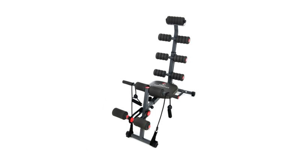
![]() USER MANUALTOTAL BODY WORKOUT SYSTEM
USER MANUALTOTAL BODY WORKOUT SYSTEM
Review the user manual carefully prior to first use. To ensure proper product operation, pay special attention to the safety precautions. Retain this user manual for further reference.
SAFETY PRECAUTIONS
To avoid damage or injury to the user or third parties, read all instructions and safety recommendations prior to use of this product. Continue to follow all instructions and guidelines.
IMPORTANT NOTICES DURING OPERATION:
- Elderly or vulnerable people should consult their doctor before using the device, even if there is no specific precondition for their health.
- If you experience pain or any abnormal sensations when using the device, stop use immediately and consult your doctor.
- Use the device on a flat surface. If it is not placed on a flat surface, the device will not be stable and could tip over resulting in injury.
- If the operation of the device begins to look abnormal, stop the exercise immediately.
- Always store in a cool, moisture-free area.
- Children and individuals with disabilities must not use the device without adult supervision.
- To avoid accidents or injuries, do not allow children or pets to get on the device.
- It should not be used by more than two people at the same time. To avoid accidents or injuries, the device should not be used while holding a baby.
- If the device fails, consult your dealer or consult the section on Warranty of this Manual.
- Do not use it for other means than those described in this manual.
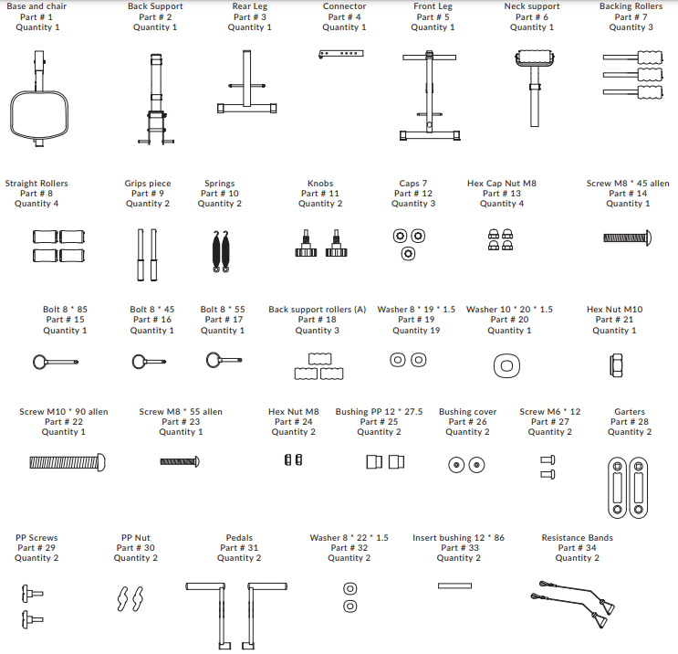
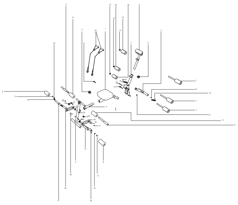
PARTS LIST:
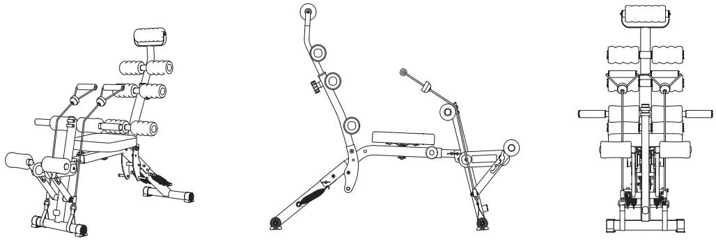
Reference Images
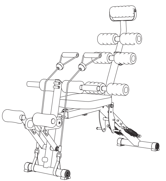
EXPLODED-VIEW DRAWING
ASSEMBLING INSTRUCTIONS
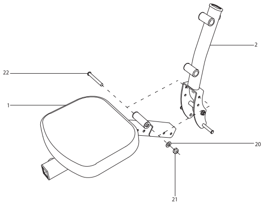
Step 1Attach the back support piece (# 2) to the base piece and seat (# 1) in the holes indicated with the dotted line of the drawing using the screw (# 22), washer (# 20), and nut (# 21) that are attached to the base piece and seat (# 1) using the 17mm (11/16”) wrench and the 5mm (13/64”) Allen key.
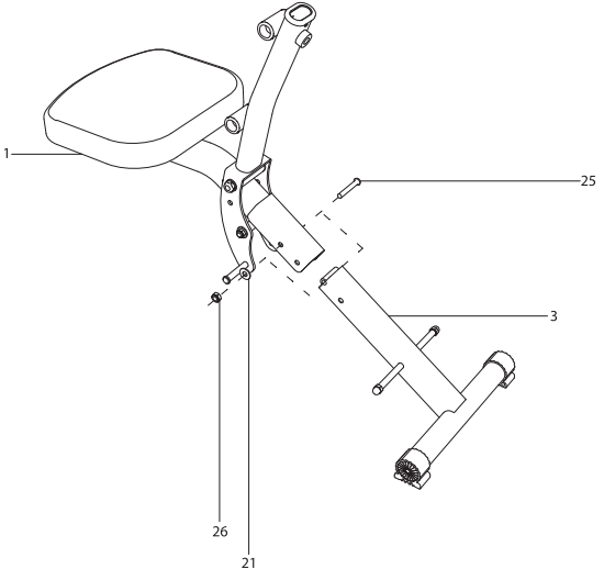
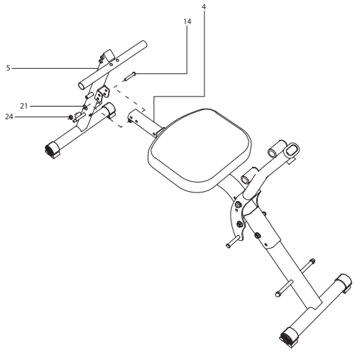
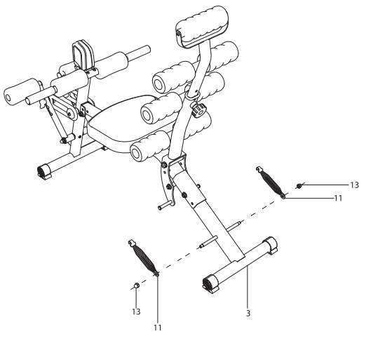
Step 2Attach the back leg piece (# 3) to the base piece and seat (# 1) at the holes marked with the dotted line of the drawing. Take the screw (# 23), washer (# 21), and nut (# 24) and place it on the rear leg (# 3). Tighten the screw, washer, and nut by using the 13mm (1/2”) wrench and 5mm (13/64”) Allen key.Use the 8 * 55 bolt (# 17) that is located in the lower hole of the rear leg piece (# 3) to fix the piece in place in active mode.
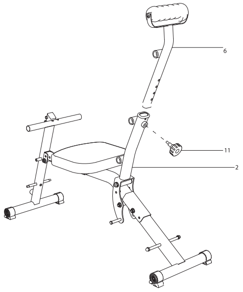
Step 3Attach the connector piece (# 4) to the base piece and seat (# 1). Once inside insert the knob (#11) and slide it to align the holes on the connector piece to the knob.These holes are used to be able to change the length of the device depending on the height of the user.Simply pull the knob and adjust the connector piece to the desired length.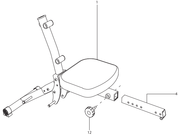
Step 4Place the front leg piece (# 5) in the connector piece (# 4) in the holes indicated with the dotted line. Using the screw (#14), washer (#21), and nut (#24) and place them in the base piece and seat (#1). Tighten the screw, washer, and nut by using the 13mm (1/2”) wrench and a 5mm (13/64”) Allen key.This hardware is inside the bag that you will find inside the packaging.Use the 8 * 55 bolt (#16) that comes inside the bag that is inside the packaging to place it in active mode.
Step 5Insert the neck support piece (#6) into the back support piece (#2). Once inside, insert the knob (#12) and slide the neck support part to align the holes to the knob.These holes are used to change the height of the neck support depending on the height of the user.
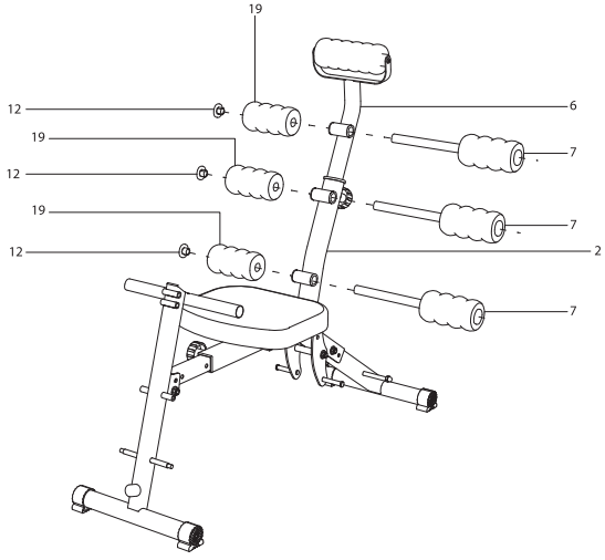
Step 6Place the back roller pieces (#7), one in each of the bushings found in the neck support (#6), and back support (#2) pieces indicated with the dotted line.Next, put the back support rollers (# 20) and at the end, place the caps (#13) on the opposite end of the back roller parts (#7).These caps come inside the bag that you will find inside the packaging.
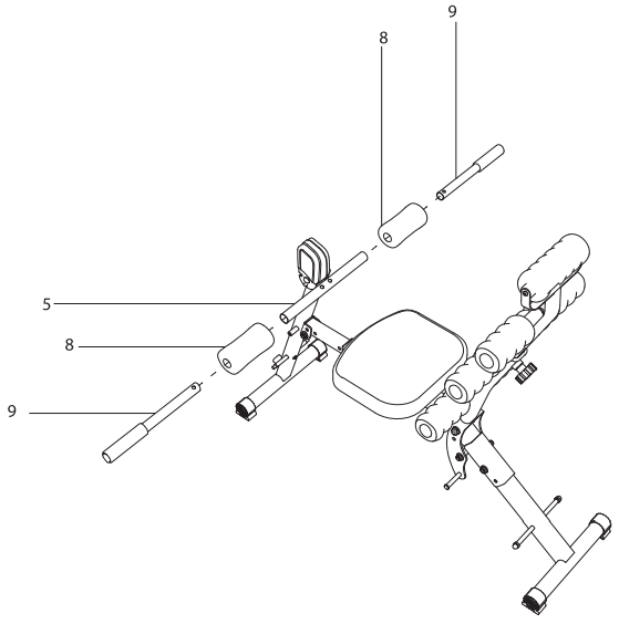
Step 7Insert the straight roller pieces (#9) into the horizontal tubes of the front leg (# 5) indicated with the dotted line. Next, place the grip pieces (#10) on the horizontal tubes of the front leg piece (#5) marked with the dotted line.
Cardio system assemblyAll the parts required to set up the cardio system are inside the box in the packaging.
Step 8Place the bushing (#33) in the hole marked with the dotted line on the front leg (#5). Next, insert the bushing piece (#25) into the ushing insert (# 33) followed by the rubber bands (#28) on the side with round holes. Finally, using the hub cover piece (#26) and the screw (#27) fix them using the 5mm (13/64”) Allen key.Make sure to place each of the parts mentioned in the previous step in the correct order in which it is specified in the drawing, using the dotted line for reference.
Step 9Insert the pedals (#31) into the threaded studs from where you previously removed the horizontal tubes attached to the middle of the front leg (# 5). Using the washers (#32) and nuts (#13) fix them by tightening them with the wrench. Finally, place the straight rollers (#8) in the horizontal tubes located on the upper part of the pedals (#31).Make sure to place each of the parts mentioned in the previous step in the correct order in which it is specified in the drawing, using the dotted line for reference.
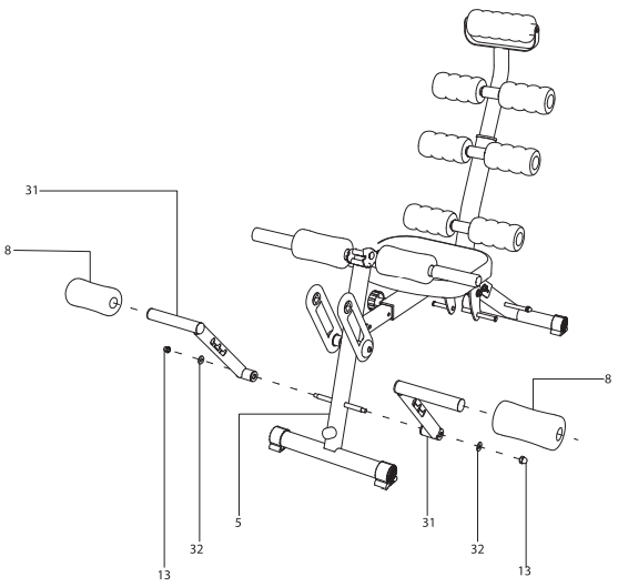
Step 10Using the PP nut (#30) and the PP screw (# 29) attach the band piece (# 28) to the pedal piece (#31).
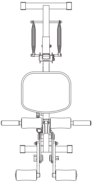
Step 11Remove the nuts (#13) found on the horizontal bolts of the middle part of the rear leg (# 3) and place the 2 springs (#10) from its lower end.
HOW TO USE
Adjust the level of back support assistance.
- To adjust the level of assistance it is necessary to place or remove the springs, only the upper part, identified by a hook that attaches to the sides of the bolt that are at the bottom of the back leg support (# 3)
- It is necessary to modify this assistance depending on the weight and physical capacity of the user.

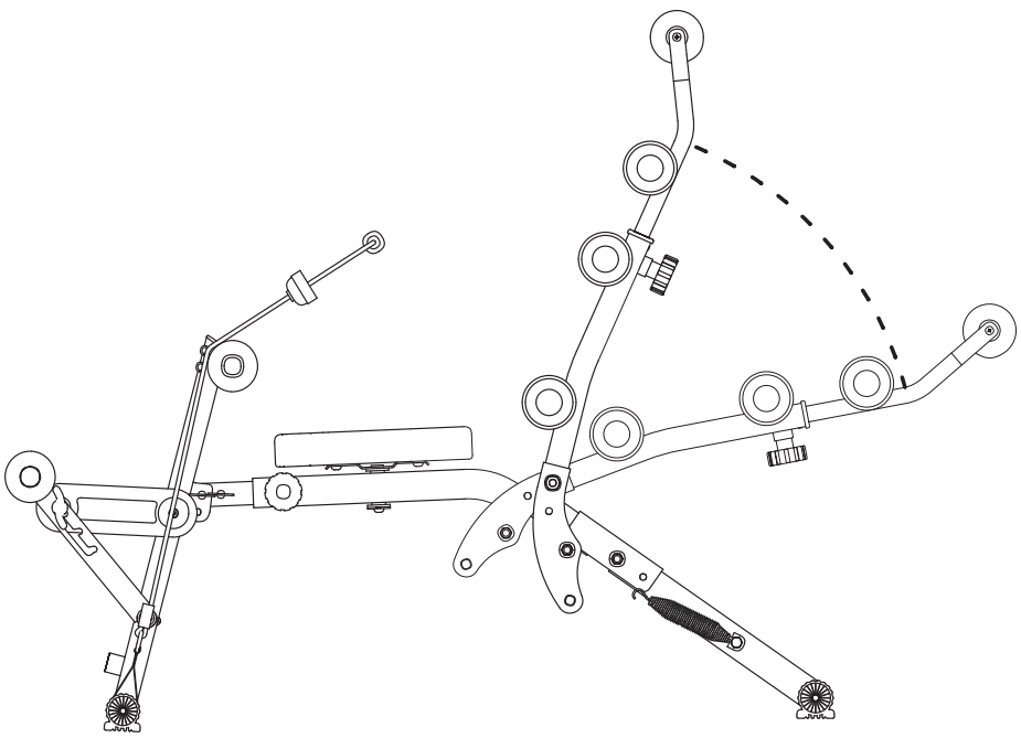
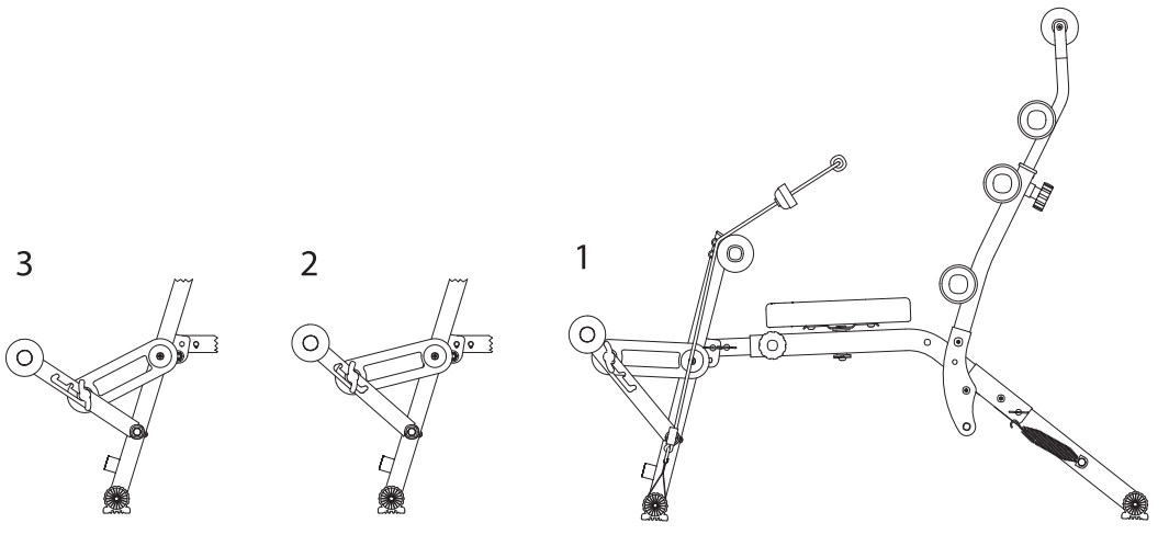
Back support position adjustment.Total Body Workout System has 4 options for placing the back support
- The Total Body Workout System has 4 options for placing the back support.
- ABS mode: Depending on the number of springs used, that will be the assisted resistance the user will get without being fixed with the 8 * 85 bolt part (#17).
- Abdominal bench mode: Place the back support in a position parallel to the ground and fix it by inserting the 8 * 85 bolt (# 17) crossing it through the hole indicated with the dotted line. It is recommended that no springs be attached for easy placement.
- Fixed mode: Position the back support vertically by inserting the 8 * 85 bolt (# 17) crossing it through the hole marked with the dotted line. It is recommended that no springs be attached for an easier setup.
- Folding mode: Remove pin 8 * 85 (# 17) and make sure that no spring is attached.
Resistance adjustment in cardio system
- The Total Body Workout System has 3 levels of resistance in its cardio system to be used depending on the physical capabilities of the user.
- To be able to modify the resistance level, loosen the PP nut, change the level and tighten again.
- Level 1 higher resistance, Level 3 lower resistance.
Resistance band placement
- The Total Body Workout System has 2 resistance bands to work the upper body, back, shoulder, biceps, triceps, and arms.
- Attach the resistance bands from their lower end to the front or rear leg depending on the exercise to perform.
- Secure the level of the resistance band to the leg correctly to prevent the leg from coming loose during workouts.

WARRANTY:
Limited Lifetime WarrantyYour Medic Therapeutics Total Body Workout System is backed by a limited lifetime manufacturer’s warranty. Medic Therapeutics will repair or replace your device at any time should it fail due to a defect in material or workmanship, subject to certain limitations.This limited warranty does not cover any damage that results from unauthorized or improper use, service, or repair. Further, it does not cover damage caused by accident, impact, negligence, or normal wear and tear. Should you discover your Medic Therapeutics Total Body Workout System is not functioning properly, please send your device to our repair center for evaluation. If your product cannot be repaired or serviced, we will reserve the right to change it for a similar or newer model.Please note that a flat rate of $60.00 will be charged to cover a service evaluation fee and return shipping of your device. All warranty claims must be accompanied by a copy of your proof of purchase from an authorized retailer. Please send your device, proof of purchase, and a check or money order in the amount of $60.00 made out to Medic Therapeutics to:
Address:Medic Therapeutics Service Center3069 Taft StreetHollywood, FL 33009Contact:[email protected]
![]()
[xyz-ips snippet=”download-snippet”]