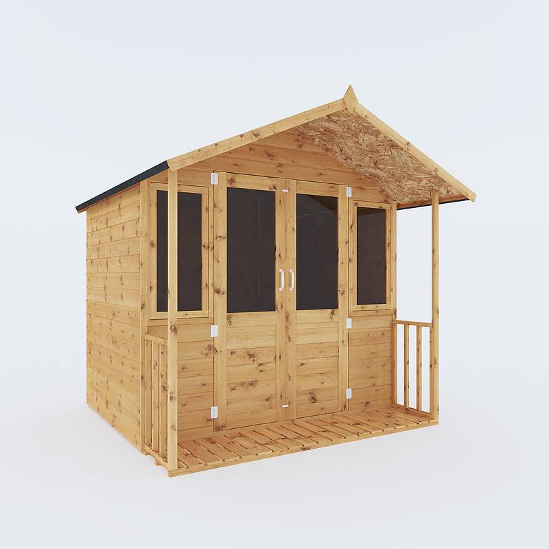
Mercia Garden Bournemouth Instruction Manual

General Instructions 03BRN0707-V4 7X7 BOURNEMOUTH
BEFORE YOU START PLEASE READ INSTRUCTIONS CAREFULLY
- Check the pack and make sure you have all the parts listed.
- When you are ready to start, make sure you have the right tools at hand (not supplied) including a Phillips screwdriver, Stanley knife, wood saw, step ladder and drill with 2mm bit.
- Ensure there is plenty of space and a clean dry area for assembly.
TIMBER
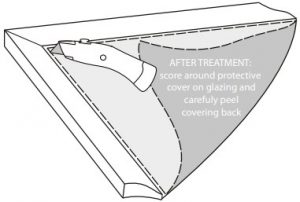
As with all natural materials, timber can be affected during various weather conditions. For the duration of heavy or extended periods of rain, swelling of the wood panels may occur. Warping of the wood may also occur during excessive dry spells due to an interior moisture loss. Unfortunately, these processes cannot be avoided but can be helped. It is suggested that the outdoor building is sprayed with water during extended periods of warm sunshine and sheltered as much as possible during rain or snow.Our buildings are pre treated with a water based treatment**; this only helps to protect the product during transit and for upto 3 months against mould. To validate your guarantee and ensure longevity of the product, it is ESSENTIAL the building is treated with a wood preserver within the first three months of assembly and thereafter in accordance with the manufactures recommendations. Care must be taken to ensure the product is placed on a suitable base.
BUILDING A BASE
When thinking about where the building and base is going to be constructed: Ensure that there will be access to all sides for maintenance work and annual treatment. Ensure the base is level and is built on firm ground, to prevent distortion. Refer to diagrams for the base dimensions, The base should be slightly smaller than the external measurement of the building, i.e. The cladding should overlap the base, creating a run off for water. It is also recommended that the floor be at least 25mm above the surrounding ground level to avoid flooding.
TYPES OF BASE
- Concrete 75mm laid on top of 75mm hard-core.
- Slabs laid on 50mm of sharp sand.
Whilst all products manufactured are made to the highest standards of Safety and in the case of childrens products independently tested to EN71 level, we cannot accept responsibility for your safety whilst erecting or using this product.Refer to the instructions pages for you specific product code
 All building’s should be erected by two adults
 Winter = High Moisture = ExpansionSummer = Low Moisture = Contraction
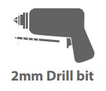 For ease of assembly, you MUST pilot drill all screw holes and ensure all screw heads are countersunk.
 CAUTIONEvery effort has been made during the manufacturing process to eliminate the prospect of splinters on rough surfaces of the timber. You are strongly advised to wear gloves when working with or handling rough sawn timber.
Protim Aquatan T5 (621)Your building has been treated with Aquatan.Aquatan is a water-based concentrate which is diluted with water, the building as been treated by the correct application of Aquatan solution and then allowed to dry.Aquatan is a decorative finish to colour the wood, which is applied industrially to timber fence panels and garden buildings.Aquatan undiluted contains: boric acid, sodium hydroxide 32% solution, aqueos mixture of sodium dioctyl sulphosuccinat and alcohols: 2, 4, 6-trichlorophenol.
03BRN0707-V4


Overall Dimensions:Length = 2233mmWidth = 2227mmHeight = 2181mm
Base Dimensions:Length = 1923mmWidth = 2082mm
- Door Gable
- Plain Side QTY 2
- Plain Gable
- Floor
- Roof Sheet QTY 2
- Master Door
- Slave Door
- Veranda Floor
- Veranda Side QTY 2
- Ridge Bar – 1457mm
- Eaves Frame – 2185mm QTY 2
- Cover Trim – 1682mm QTY 4
- Fascia – 1192mm QTY 4
- Angled Fascia Block – 340mm
- Fascia Block – 140mm QTY 2
- Finial QTY 2
- Veranda frame – 1690mm QTY 2
- “L” Bracket QTY 2
- Butt Hinge QTY 6
- Turn Button QTY 2
- Barrel Bolt QTY 2


Nail Bag
35mm Bolt x4![]() 50mm Screw x44
50mm Screw x44![]() 40mm Screw x28
40mm Screw x28![]() 30mm Screw x56
30mm Screw x56![]() 25mm Screw x38
25mm Screw x38![]() 16mm Black Screw x2
16mm Black Screw x2![]() 16mm Screw x4
16mm Screw x4![]() 10mm Screw x10
10mm Screw x10![]() Felt Tacks x122
Felt Tacks x122![]()
Pre AssemblyRemove the transportation blocks from the bottom of each panel before beginning the assembly.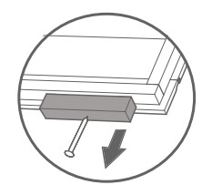
Step 1Place the oor onto a firm and level base. Ensure the base has suitable drainage & is free from areas where standing water can collect.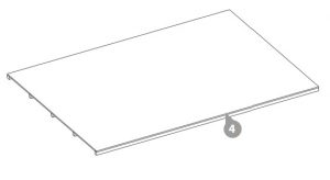
Step 2Attach the doors to the door gable with 3x butt hinges per door using 36x25mm screws.Ensure to screw the hinges into the framing.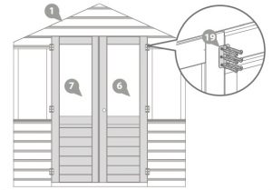
36x25mm Screws
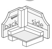
Step 3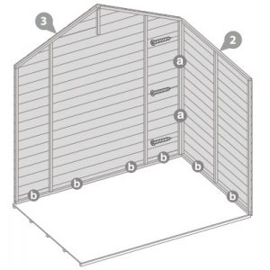 Place the plain gable and the first plain side onto the floor.
- Fix the corners with 50mm screws as shown in the illustration, making sure the gable sits inside the panel.
- Do not secure the building to the floor until the roof is fitted.
3x50mm Screws
Step 4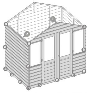 Place the door gable and the second plain side onto the floor.
- Fix the corners with 50mm screws as shown in the illustration, making sure the gable sits inside the panel.
- Do not secure the building to the floor until the roof is fitted.
9x50mm Screws
Step 5
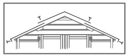
Attach the “L” brackets centrally to the ridge bar using 2x30mm screws per bracket.
Measure 67mm from each side of the ridge bar and mark with a pencil. Align the front edge of the bracket with the pencil mark as shown in the illustration.4x30mm Screws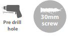
Step 6 Place the assembled ridge bar inbetween the gables, resting on top of the blocks.Secure to the gables using 2x30mm screws per side.Adjust the “L” brackets if needed.4x30mm Screws
Step 7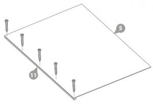 Fix an eaves frame to the edge of each roof sheet with 5x30mm screws per frame.10x30mm Screws
Step 8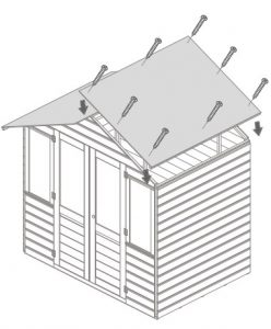 Place the assembled roof panels onto the building as shown in the illustration. Fix into place using 8x30mm screws per side, ensuring the roofs are flush with the top of the gables.The roof panels should be level with the back of the building leaving an overhang over the front.
16x30mm Screws
Step 9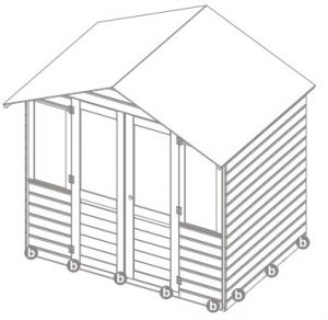
Once the roof is fixed in place, secure the building to the floor
Ensure to screw through the framing into the floor bearers.
18x50mm Screws
Step 10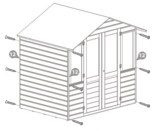 Attach the cover trims to each corner of the building using 3x30mm screws per cover trim.
12x30mm Screws.

Step 11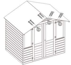 Fit the angled fascia block to the apex of the roofs, making sure it is flush with the roof sheet, securing in place with 4x40mm screws.Attach the rectangular blocks approximately half way along each roof sheet, fixing into place with 2x40mm screws per block.
8x40mm Screws
Step 12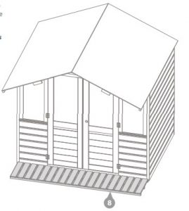 Place the veranda floor on the ground flush to the door gable as shown in the illustration.
* Ensure the veranda floor sits centrally to the building.
Step 13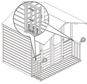
Align the veranda sides against the door gable and flush to ends of the veranda floor, secure to the building and to veranda floor with 6x50mm screws per side as shown in the illustration.
12x50mm Screws
Step 14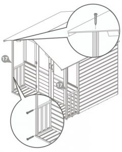
Place the veranda frame underneath the roof overhang, aligning the frame flush to edge of the veranda rail.Secure to the veranda rail and to the roof using 3x40mm screws per frame.
* Ensure the framing follows the same direction as the roof.
6x40mm Screws
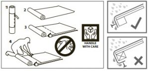
Step 15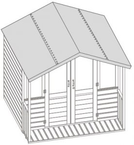 Cut the felt into 3 sheets and lay onto the roof as shown in the illustration ensuring there is approximately 50mm of overhang around the building.Fix onto the building using 75x felt tacks at 100mm intervals.120x Felt Tacks
* Felt size: 2333mm
Step 16Fix the fascias and finials to the building using 6x40mm screws per side, ensuring to screwthrough the boards into the fascia blocks.
12x40mm Screws
Step 17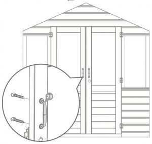 Attach the door handles to the doors using the 35mm bolts included with the door handle.Pre drill a hole approximately 3mm and fix the handle from the inside with the provided bolts4x35mm Bolt
Step 18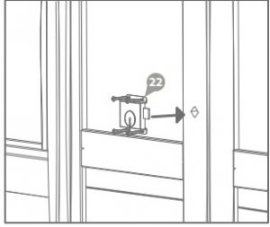 Fix the presslock to the inside of the master door, making sure to align the barrel and the key hole.Secure to the master door with 4x16mm screws.Ensure the key turns fully without any restrictions.4x16mm Screws
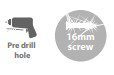
Step 19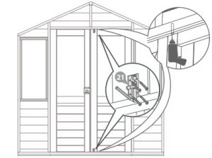 Attach to the barrel bolts to the top and bottom of the slave door using 4x10mm screws per bolt.Mark the position of the bolt with a pencil on the framing and drill a hole to site the bolts.8x10mm Screws
Step 20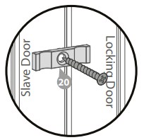
Fix the turn buttons into place at the top and bottom of door as shown in the diagram. The turn buttons help to keep the doors alligned during high and low levels of moisture.
2x16mm Black Screws

For assistance please contact customer care on: 01636 880514Mercia Garden Products Limited, Sutton On Trent, Newark, Nottinghamshire, NG23 6QNwww.merciagardenproducts.co.uk
References
[xyz-ips snippet=”download-snippet”]