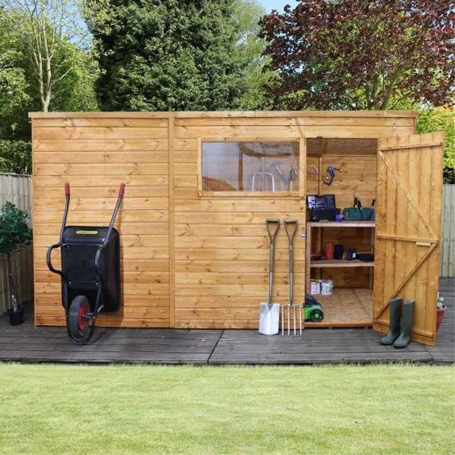

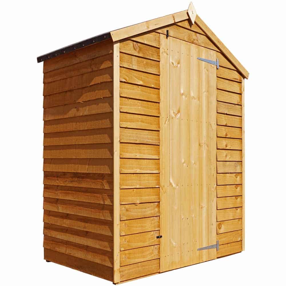
Mercia Garden Overlap Shed
Instructions
BEFORE YOU START PLEASE READ INSTRUCTIONS CAREFULLY
- Check the pack and make sure you have all the parts listed.
- When you are ready to start, make sure you have the right tools at hand (not supplied) including a Phillips screw-driver, Stanley knife, Wood saw, Step ladder, Hammer and a Drill with 2mm bit.
- Ensure there is plenty of space and a clean dry area for assembly.
TIMBER
As with all natural materials, timber can be affected during various weather conditions. For the duration of heavy or extended periods of rain, swelling of the wood panels may occur. Warping of the wood may also occur during excessive dry spells due to an interior moisture loss. Unfortunately, these processes cannot be avoided but can be helped. It is suggested that the outdoor building is sprayed with water during extended periods of warm sunshine and sheltered as much as possible during rain or snow.
Once your garden building has been installed it will need to be treated as soon as possible and annually to prevent the timber from deteriorating and to waterproof it. This is required to maintain the anti-rot guarantee.Dip Treated buildings – Require a preservative treatment to protect against rot and decay and a waterproof treat-ment to prevent water ingressPressure Treated buildings – Require a waterproof treatment to prevent water ingressLog Cabins – Are supplied untreated and require a preservative and waterproofing treatment.
BUILDING A BASE
When thinking about where the building and base is going to be constructed:
- Ensure that there will be access to all sides for maintenance work and annual treatment.
- Ensure the base is level and is built on firm ground, to prevent distortion. Refer to diagrams for the base dimensions, The base should be slightly smaller than the external measurement of the building, i.e. The cladding should overlap the base, creating a run off for water. It is also recommended that the floor be at least 25mm above the surrounding ground level to avoid flooding.
TYPES OF BASE
- Concrete 75mm laid on top of 75mm hard-core.
- Slabs laid on 50mm of sharp sand.
Whilst all products manufactured are made to the highest standards of Safety and in the case of children’s products independently tested to EN71 level, we cannot accept responsibility for your safety whilst erecting or using this product.Refer to the instructions pages for your specific product code
- All buildings should be erected by two adults
- For ease of assembly, you MUST pilot drill all screw holes and ensure all screw heads are countersunk.
- For ease of assembly, you will need a tape measure to check dimensions of components.
- Winter = High Moisture = ExpansionSummer = Low Moisture = Contraction
- CAUTIONEvery effort has been made during the manufacturing process to eliminate the prospect of splinters on rough surfaces of the timber. You are strongly advised to wear gloves when working with or handling rough sawn timber.
**Protim Aquatan T5 (621)**
Your building has been treated with Aquatan.Aquatan is a water-based concentrate which is diluted with water, the building as been treated by the correct application of Aquatan solution and then allowed to dry.Aquatan is a decorative finish to colour the wood, which is applied industrially to timber fence panels and garden buildings.Aquatan undiluted contains: boric acid, sodium hydroxide 32% solution, aqueos mixture of sodium dioctyl sulphosuccinat and alcohols: 2, 4, 6-trichlorophenol.
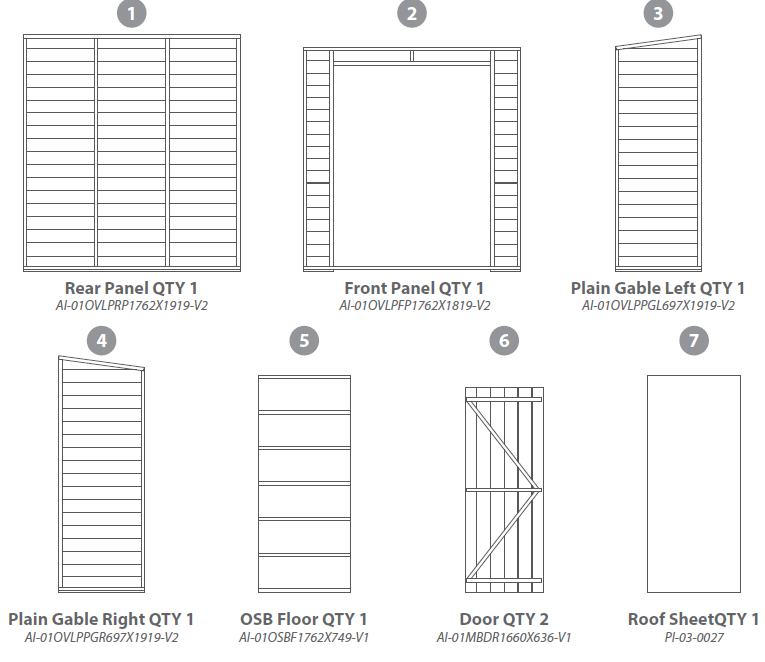
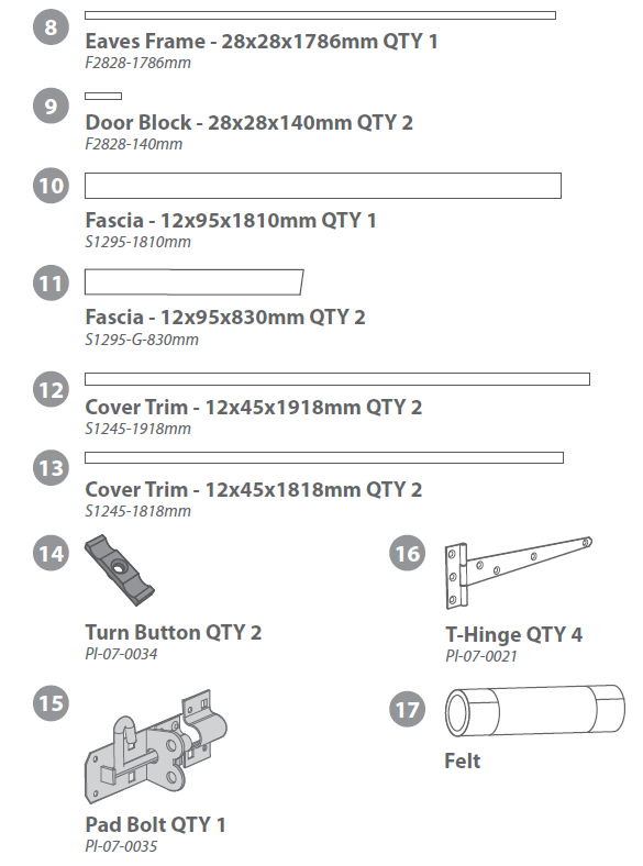
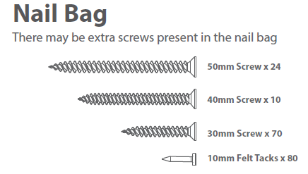
Building Content:
Nail Bag
Pre-Assembly
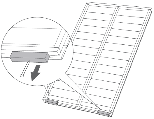
Remove the transportation blocks from the bottom of each panel before beginning assembly.Each panel should have two blocks.
Step 1: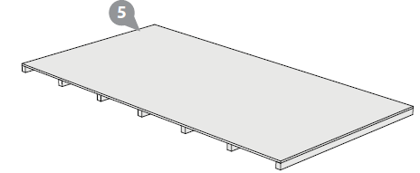
Parts Needed – No. 5 QTY 1Place the Floor (No. 5) on a firm and level base, ensure base has suitable drainage free from areas where standing water can collect. (see front page on base requirements).
Step 2:
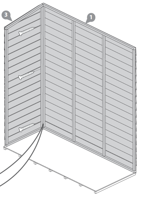
Parts Needed – No. 1 QTY 1Place the Rear Panel (No.1) and the Plain Gable Left (No.3) onto the Floor (No.5), ensuring there is equal spacing between the floor and cladding on all sides.Fix the corners with 3x50mm screws as shown in diagram.Do not secure the building to the floor until the roof is fitted.
Step 3:

Parts Needed – No. 2 QTY 1Place the Front Panel (No. 2) and the Plain Gable Right (No.4) onto the Floor (No.5), ensuring there is equal spacing between the floor and cladding on all sides.Fix the corners with 3x50mm screws per corner, as shown in diagram.Do not secure the building to the floor until the roof is fitted.
Step 4:
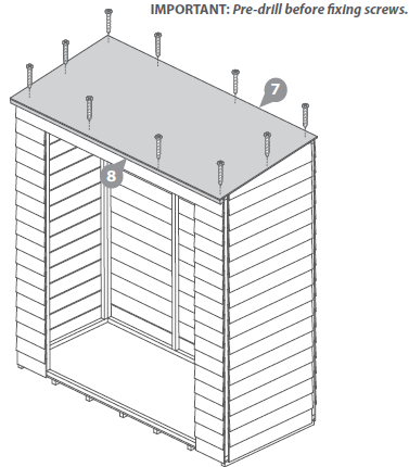
Parts Needed – No. 7 QTY 1Fix the Eaves Frame (No. 8) to the longest edge of the Roof Sheet (No.7) using 4x30mm screws.Place the Roof into position, ensuring the Eaves Frame (No. 8) fits butt against the Front Panel cladding.Fix in place using 10x30mm screws, as shown in the diagram.
Step 5: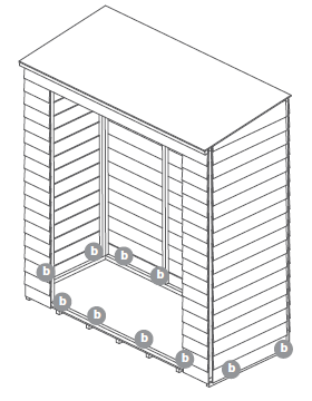
Once the roof is fitted, fix the panels to the floor using 50mm screws in line with the floor bearers.
Step 6:
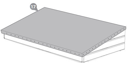
Parts Needed – No. 17 QTY 1Lay the Felt (No. 17) onto the roof as shown in the diagram.Ensure there is 50mm of overhang around each side.Fix in place using felt tacks at 100mm internals.
Step 7:
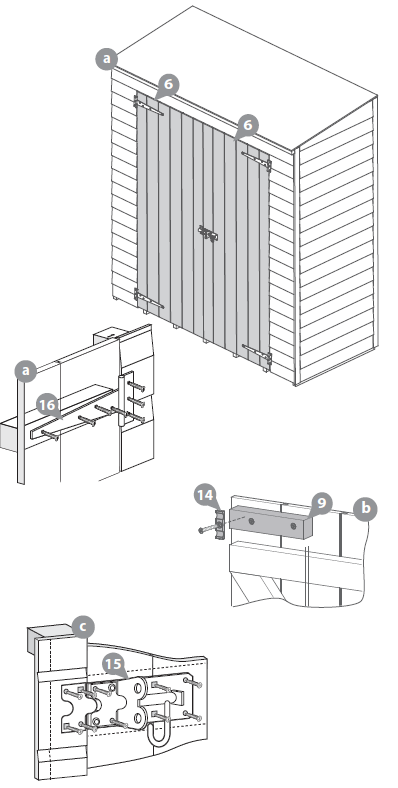
Parts Needed – No. 6 QTY 2
- Fix the Hinges (No.16) to the Doors (No.6) using 4x30mm screws per hinge, ensuring the screws are located into the door framing.Locate the Doors (No.6) onto the building, ensuring there is equal spacing between each door and the framing of the front panel and that they open and close freely.Secure the doors to the building by fixing the T-hinges to the cladding using 3x30mm screws per hinge.
- Fix the Door Blocks (No. 9) to the top and bottom framing(Internally) of the Door (No. 6) using 2x30mm screws per block.Fix the Turn Buttons (No. 14) to the Door Blocks (No.9) using 1x30mm screw per turn button.
- Align the Pad Bolt (No.15) with the horizontal door brace. Fix in place using 6x30mm screws.Fix the Pad Bolt retainer (No.15) to the opposite doors framing using 4x30mm screws.
Step 8: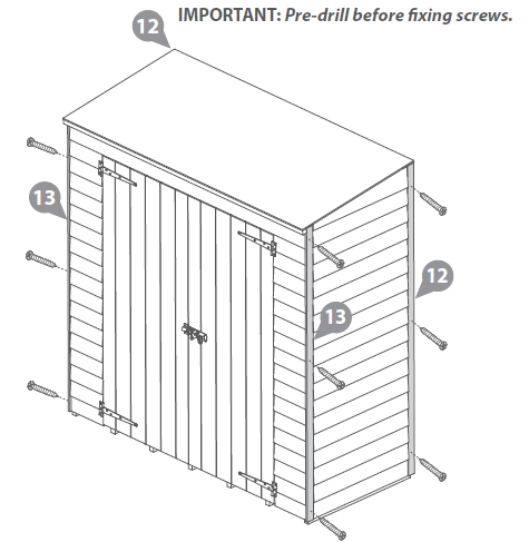
Fix the Smaller Cover Trims (No. 13) to the front of the building using 3x30mm screws per trim.Fix the Larger Cover Trims (No. 12) to the back of the building using 3x30mm screws per trim.
Step 9:
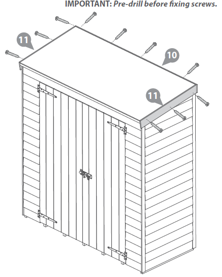
Locate Fascias (No. 11) onto the sides of the building and fix in place using 3x40mm screws per fascia.Locate Fascia (No. 10) onto the back of the building and fix in place using 4x40mm screws.
References
[xyz-ips snippet=”download-snippet”]