892486K01ANALOG GAUGE INTERFACE (AGI)SMARTCRAFT
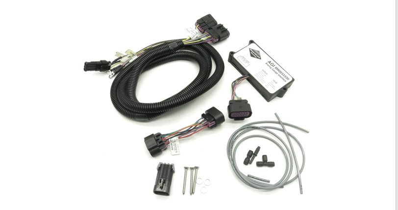
Analog Gauge lnterface (AGl) Installation
NOTE: This Analog Gauge lntefface (AG| can only be used with the 14 pin Digital Throttle and Shift (Dfq system to drive analog and/or SmartCraft System Link gauges. For analog gauges, use ring terminals on AGI harness to connect to analog sender inputs on gauge backs, and tape back any unused terminals. For SmartCraft System Link gauges, use 3 pin System Link connection on AGI harness. The AGI system can support /0 System Link gauges per helm, 2 helms maximum.
IMPORTANT: Mount AGI module with wires coming out of potting facing downward to prevent moisture from collecting at base of wires and wicking into module. Route and secure all wires and harnesses away from hot or moving parts.
- With screws and washers supplied in kit, mount the AGI module securely under dash or helm in close proximity to gauges being used.
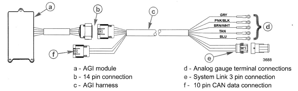
- Refer to the following table for AGI harness wire color/analog gauge sender input connections. Tape back any unused terminals. Secure connections per gauge manufacturers’ specifications.
Analog Gauge Type AGI Harness Wire Color Tachometer Gray Oil Pressure/Oil Level Blue Water Temperature Tan Trim Positions BrownAtVhite Fuel Level Pink/Black 
- Route and connect wire from key switched 12 volt positive power source to analog gauges. Secure connections per gauge manufacturers’ specifications.
- Route and connect ground wire from analog gauges to a common ground. Secure connections per gauge manufacturers’ specifications.
- Connect any SmartCraft System Link gauges to 3 pin System Link connection. The AGI system can support 10 System Link gauges per helm, 2 helms maximum.
- Plug 14 pin AGI harness connection into AGI module.
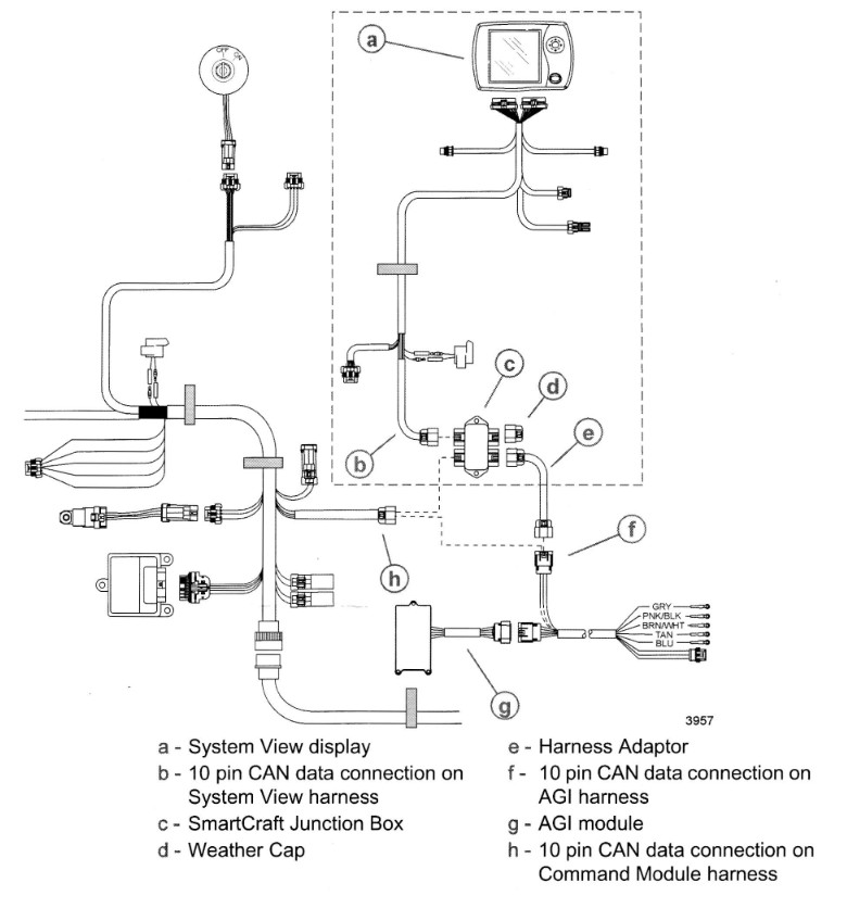
- Connect 10 pin CAN data harness connection on command module harness to AGI harness.a. lf SmartCraft System View is not being used, plug 10 pin CAN data connection on AGI harness directly into 10 pin CAN data connection on command module harness.b. lf SmartCraft System View is being used, a junction box and harness adaptor will be required. Plug 10 pin CAN data connection on command module harness, 10 pin CAN data connection on System View harness, and one end of harness adaptor into junction box. Plug 10 pin CAN data connection on AGI harness into another end of harness adaptor. lnsulate any unused connection ports on junction box with weather caps.
Typical AGI Application with System View
Configuring Analog/Digital Tachometer Signal through PCM
IMPORTANT: The engine Propulsion Control Module (PCM) tachometer configuration factory default has been set to an analog. This will allow the operation of one analog tachometer. Depending on the desired use of analog/digital gauges, the PCM set-up may have to be configured from analog to a digital.Following are optional uses of analog and digital gauges and the setting for the tachometer configuration in the PCM necessary to run them.
| Gauge Configuration | Analog | Digital |
| Analog Tachometer Only | x | |
| System Link Gauges used with System View, System Monitor, or System Tach | – | – |
| System Link Gauges used in conjunction with System Link Adaptor Harness and Command Module Harness without the use of System View, System Monitor or System Tach | x | |
| AGI used with or without System View, System Monitor or System Tachometer, to run analog and System Link Gauges | x |
The Digital Diagnostic Tool (DDT) or Computer Diagnostic System (CDS) can be used to select analog or digital PCM tachometer configuration.
PCM Configuration with DDT
IMPORTANT: The use of DDT cartridge 1.3.1 or above must be used for PCM configuration.1. Attach DDT to engine and power up. Refer to DDT Owners Manual if needed.2. Press 1. “MERCURY MARINE”3. Press 1. “TO CONTINUE”4. Press 2. “MANUAL TEST”5. Arrow down and Press 5. “SPECIAL FUNCTION”6. Arrow down and Press 9. “TACH LINK CONFIG”7. “CONFIGURE TACH SOFTWARE DRIVER?” – Press 1. “YES”8. “TACH LINK CONFIG” – Press 1. “FOR LINK” (Digital) – Press 2. “FOR ANALOG”9. After task completion confirmation, Press “MODE” to Exit
PCM Configuration with CDS
1: Attach CDS to engine. Refer to on-line help if needed.2. From Logon screen, navigate to Engine Select screen.3. From Engine Select screen fill in engine type information and select Tool Box.4. From Tool Box screen, select Active Diagnostics.5. From Active Diagnostics screen, scroll down and select Tach Link Config.6. To change PCM configuration from default of analog to digital, select Enable and then select Run,7. To change PCM configuration from digital to analog, select Disable and then select Run.
Products of Mercury MarineW6250 Pioneer RoadFond du Lac, Wl 54936-1939
Mercury, Mercury Marine, MerCruiser, Mercury Mercruiser, Mercury Racing, Mercury Precision Parts, mercury Propelleß, Mariner, Quicksilver, #1 On The Water, Alpha, Bevo, Pro Max, OptiMax, Sport-Jet, K-Planes, Mercathode, Ridecuide, Smartcraft, Zero Effort, lV with Waves logo, Mercury with Waves logo, and Smartcraft logo are all registered trademarks of Brunswick Corporation. l,.4ercury Product Protection logo is a registered Servicemark of Brunswick Corporation.
[xyz-ips snippet=”download-snippet”]