Apogee Instruments SN-500 Net Radiometer
INTRODUCTION
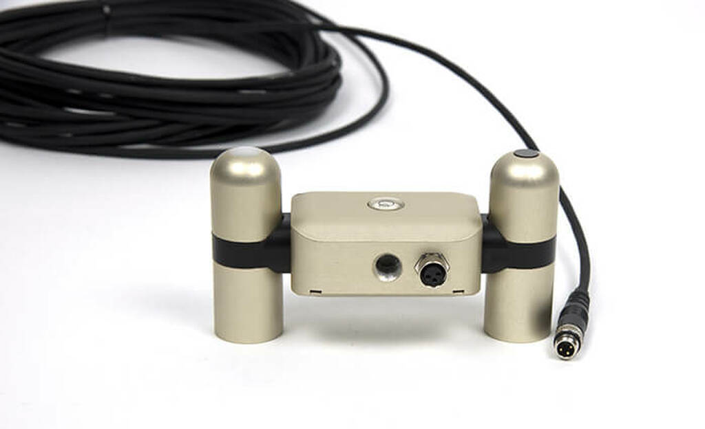
The Apogee Instruments SN-500 Net Radiometer is a four-component net radiometer designed for continuous measurement of net radiation in outdoor environments. Thenet radiometer uses four filtered blackbody thermopile sensors to measure the four components of net radiation independently. An upward-facing pyranometer and pyrgeometer pair measures the downwelling shortwave and longwave radiation, respectively, while a downward-facing pyranometer and pyrgeometer pair measures upwelling shortwave and longwave radiation. The four radiation components can be used individually or combinedto yield several important parameters including net radiation, which is a key variable in the surface energy balance, shortwave irradiance, net short- and longwave radiation, albedo, and many others.The information in this document explains how to install the required hardware to mount the Apogee Net Radiometer that has been preconfigured by METER Group to work seamlessly with METER ZENTRA series data loggers. Details of how the ZENTRA system handles the data are also included. Please read this document carefully in its entirety before going out to the field.For more information on the Apogee net radiometers, please review the Net Radiometer User Manual or visit the Apogee Net Radiometer product page(apogeeinstruments.com/net-radiometer).
INSTALLATION
Follow the steps listed in Table 1 to install the Apogee Net Radiometer in the field. The mounting rod as well as mounting brackets and fastening hardware are included with the sensor. Other tools will need to be provided.
Table 1 InstallationTools Needed
- Wrench 13 mm (0.5 in)
- Philips screwdriver
- Mounting post 33.0 to 53.3 mm (1.3 to 2.1 in) diameter post, pole, tripod, tower, or other similar infrastructure that extends above the canopy
- Mounting rod (included)
- Mounting bracket Model AM-500 (included)
- METER ZENTRA series data logger ZL6 or EM60
- METER ZSC Bluetooth® Sensor Interface (optional)
- METER ZENTRA software ZENTRA Utility, ZENTRA Utility Mobile, or ZENTRA Cloud
| Preparation | Conduct System Check |
| Mounting | Install on Mounting Post
Use the U-bolts to mount the mounting bracket and sensor (Section 2.1). The U-bolts are compatible with most meterological stands, poles, tripods, and other mounts. Secure the System Tighten the U-bolt nuts by hand until hand-tight, and then tighten with a wrench. Ensure the net radiometer remains level. CAUTION: Do not overtighten U-bolts. Secure and Protect Cables NOTE: Improperly protected cables can lead to severed cables or disconnected sensors. Cabling issues can be caused by many factors such as rodent damage, driving over sensor cables, tripping over cables, not leaving enough cable slack during installation, or poor sensor wiring connections. Install cables in conduit or plastic cladding when near the ground to avoid rodent damage. Gather and secure cables between the sensors and the data logger to the mounting post in one or more places to ensure cable weight does not pull the plug free from its port. Connect to Data Logger Plug the sensor into a data logger. Use the data logger to make sure the sensor is reading properly. Verify these readings are within expected ranges. For more instructions on connecting to data loggers, refer to Section 2.2. |
INDEX
Ccables 3, 5, 6connecting 5customer support 7Ddata 6data logger. See ZENTRA series data loggersIinstallation 2–3mounting 3preparation 3tools needed 2Mmounting 2mounting bracket 2Nnet radiometer 2, 4Rrecalibration 6Sstereo plug connector 5Ttroubleshooting 6UU-bolt 3, 4user manual 2ZZENTRA series data loggers 2, 3, 5ZENTRA software Cloud 2, 6 Utility 2, 5, 6ZSC 2
CUSTOMER SUPPORT
NORTH AMERICACustomer support representatives are available for questions, problems, or feedback Monday through Friday, 7:00 am to 5:00 pm Pacific time.
Email:[email protected][email protected]Phone: +1.509.332.5600Fax: +1.509.332.5158Website: metergroup.com
EUROPECustomer support representatives are available for questions, problems, or feedback Monday through Friday, 8:00 to 17:00 Central European time.Email:[email protected][email protected]Phone: +49 89 12 66 52 0Fax: +49 89 12 66 52 20Website: metergroup.de
If contacting METER by email, please include the following information:Name Email addressAddress Instrument serial numberPhone Description of the problemNOTE: For products purchased through a distributor, please contact the distributor directly for assistance.
USING APOGEE NET RADIOMETERS WITH ZENTRA SYSTEM
SET UP MOUNTING ASSEMBLY
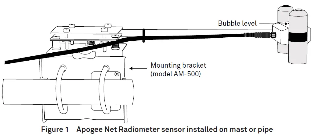
Apogee net radiometers must be level to accurately measure the four components of net radiation. Each net radiometer purchased from METER comes with an AM-500 Net Radiometer Mounting Bracket. The AM-500 can be mounted to either a horizontal or vertical post depending on which set of U-bolt holes are used. However, mounting to a horizontal arm that extends away from the main mounting mast is highly recommended.
- Align the cable M8 connector pins with the sensor M8 connector holes and seat connectors fully.
- Tighten the cable screw until hand-tight.M8 connectors are easy to overtighten. Do not use pliers or other tools to tighten this connector.
- Attach the mounting bracket either to a horizontal arm (Figure 2) or vertical post using the included U-bolts.

- If installation is in the Northern Hemisphere, ensure the sensor is oriented to the South of the main mounting mast.If installation is in the Southern Hemisphere, ensure the sensor is oriented to the North of the main mounting mast.
- Thread the mounting rod into the body of the net radiometer.
- Clamp the mounting rod into the AM-500 mounting bracket using the integrated Philips screws.
- Use the Philips screws on the mounting bracket to level the sensor according to the bubble level on the top of the sensor.
CONNECT TO METER ZENTRA SERIES LOGGER
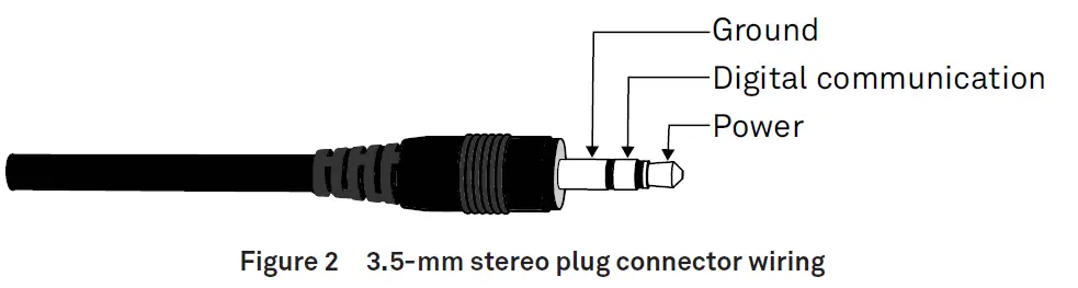
Apogee net radiometers are preconfigured by METER and work seamlessly with METER ZENTRA series data loggers. The sensors come with a 3.5-mm stereo plug connector(Figure 2) to facilitate easy connection with the data loggers. Apogee sensors come standard with a 5-m cable.
Check the METER download webpage for the most recent data logger firmware. Logger configuration may be done using either ZENTRA Utility (desktop and mobile application) or ZENTRA Cloud (web-based application for cell-enabled ZENTRA data loggers).
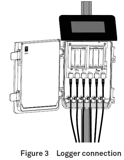
- Plug the stereo plug connector into one of the sensor ports on the logger (Figure 3).
- Connect to the data logger via ZENTRA Utility with a laptop and USB cable or ZENTRA Utility Mobile app with a mobile device supporting Bluetooth® communication.
- Use ZENTRA Utility to scan the ports and make sure the sensors were properly identifi ed by the logger and are reading properly.METER data loggers should automatically recognize the Apogee sensor.
- Use ZENTRA Utility to set the measurement interval.
- Use ZENTRA Utility to confi gure communication settings for data transfer to ZENTRA Cloud.
Sensor data can be downloaded from METER data loggers using either ZENTRA Utility or ZENTRA Cloud. Refer to the logger user manual for more information.
DATA INTERPRETATION
Apogee net radiometers used with the ZENTRA system report the four individual components and the combined net radiation in units of watts per square meter (W/m2). Various other combinations of the individual components (net short- and longwave radiation, albedo, etc.) can be calculated during postprocessing, and some are included as environmental model options in the ZENTRA Cloud reports page. Additionally, the sensor orientation information is provided in the metadata tab of ZENTRA Cloud and ZENTRA Utility file downloads (Microsoft® Excel® spreadsheet) and on the measurement configuration page of ZENTRA Cloud. Sensor orientation is reported as the sensor zenith angle in units of degrees, with a zenith angle of 0° indicating a sensor oriented straight up.
TROUBLESHOOTING
This troubleshooting section details possible major problems and their solutions. If the problem is not listed or these solutions do not solve the issue, contact Customer Support.
Table 2 Troubleshooting
| Problem Possible Solution | |
| Sensor not responding | Check power to the sensor and logger.Check sensor cable and stereo plug connector integrity.Check that the SDI-12 address of the sensor is 0 (factory default). Check this with ZENTRA Utility by going to Actions, select Digital sensor terminal, choose the port that sensor is on, and send the ?I! command to the sensor from the dropdown menu. |
| Sensor values are not reasonable | Verify the sensor is not shaded.Verify the orientation angle of sensors. |
| Cable or stereo plug connector failure | If the stereo plug connector is damaged or needs to be replaced, contact Customer Support for a replacement connector or splice kit.If a cable is damaged refer to the METER wire-splicing guide for cable repair. |
 report this ad
It is recommended that Apogee net radiometers are returned for recalibration every 2 years. Visit Apogee repairs (apogeeinstruments.com/recalibration-and-repairs) or contact Apogee Technical Support ([email protected]) for details.
References
[xyz-ips snippet=”download-snippet”]