METER Apogee Instruments NDVI and PRI sensors Instruction Manual
METER Apogee Instruments NDVI and PRI sensor
1. INTRODUCTION
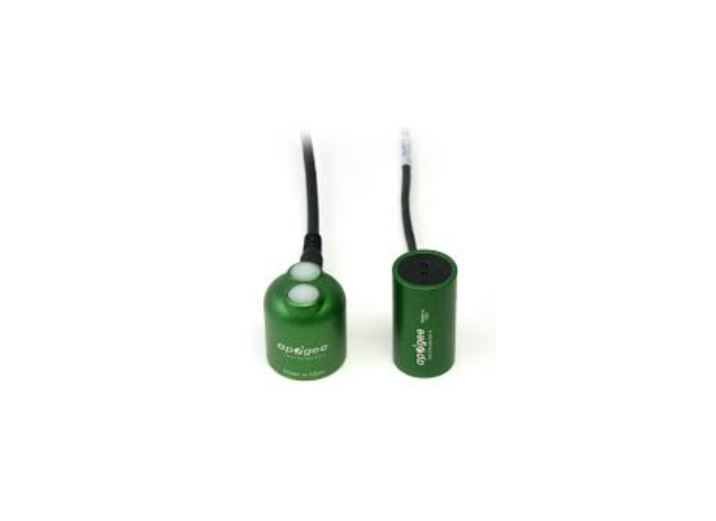
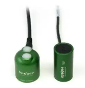
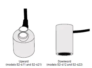
Apogee Instruments NDVI and PRI sensors are two-band radiometers measuring radiation in discrete wavebands from both incoming (S2-411, S2-421) and reflected (S2- 412, S2-422) sources. Reflectance derived from paired upward and downward facing sensors can be used to calculate Normalized Difference Vegetation Index (NDVI) or Photochemical Reflectance Index ( PRI), depending upon which sensor set is being used.The information in this document explains how to install the required hardware to mount Apogee NDVI or PRI sensors that have been preconfigured by METER Group to work seamlessly with METER ZENTRA series data loggers. Details of how the ZENTRA system handles the data are also included. Please read this document carefully in its entirety before going out to the field.For more information on Apogee sensors, please review the sensor user manuals on the respective Apogee product pages:S2-411 and S2-412 NDVI sensors (apogeeinstruments.com/ndvi-sensor-support) S2-421 and S2-422 PRI sensors (apogeeinstruments.com/ pri-sensors)
2. INSTALLATION
Follow the steps listed in Table 1 to install Apogee sensors in the field. Mounting brackets and nylons screws are included with the sensor. Other tools will need to be provided.Table 1 Installation
| Tools Needed | Wrench 13 mm (1/2 in)Flathead screwdriverPhillips screwdriver, for the AM-400 mounting bracketMounting post 33.0 to 53.3 mm (1.3 to 2.1 in) diameter post, pole, tripod,tower, or other similar infrastructure that extends above the canopyMounting bracket + leveling plate Model AL- 120 (for upward-facing sensors)or AM-400 (for downward-facing sensors)Nylon screw 110-32 x 3/8METER ZENTRA series data logger ZL6 or EM60METER ZSC Bluetooth® Sensor Interface (optional)METER ZENTRA software ZENTRA Utility, ZENTRA Utility Mobile, orZENTRA Cloud |
| Preparation | Conduct System CheckMETER strongly recommends setting up and testing the system (sensors anddata loggers) in the lab or offi ce.Inspect and verify all components are intact.Visit the data logger product page for the most up-to-date software and fi rmware.Verify all sensors are functional and read within expected ranges.Consider the SurroundingsChoose a location that allows the hemispherical view sensors to be above theplant canopy or in a position where the view of the sky is unobstructed (suchas a large canopy gap or forest clearing).Field stop sensors should also be mounted above a canopy, but there may beinstances where an oblique or side view of the canopy is more practical.Ensure the sensor is not shaded from nearby objects (weather stations,mounting posts, etc.). |
| Mounting | Install on Mounting PostUse the U-bolt to mount the upward- or downward-facing sensor appropriately(Section 2.1). The U-bolt is compatible with most meterological stands, poles,tripods, and other mounts.Secure the SystemTighten the U-bolt nuts by hand until hand-tight, and then tighten with a wrench.CAUTION: Do not overtighten U-bolt. |
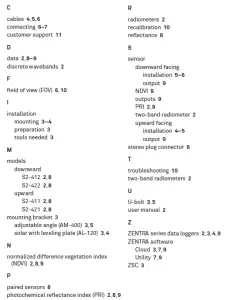
INDEX
5. CUSTOMER SUPPORT
 5. CUSTOMER SUPPORT
NORTH AMERICACustomer support representatives are available for questions, problems, or feedbackMonday through Friday, 7:00 am to 5:00 pm Pacific time.Email: Phone: +1.509.332.5600Fax: +1.509.332.5158Website: metergroup.com
EUROPE
Customer support representatives are available for questions, problems, or feedbackMonday through Friday, 8:00 to 17:00 Central European time.Email: Phone: +49 89 12 66 52 0Fax: +49 89 12 66 52 20Website: metergroup.deIf contacting METER by email, please include the following information:NameAddressPhoneEmail addressInstrument serial numberDescription of the problemNOTE: For products purchased through a distributor, please contact the distributor directly for assistance.
| Mounting(continued) | Secure and Protect CablesNOTE: Improperly protected cables can lead to severed cables or disconnected sensors.Cabling issues can be caused by many factors such as rodent damage, driving over sensorcables, tripping over cables, not leaving enough cable slack during installation, or poorsensor wiring connections.Install cables in conduit or plastic cladding when near the ground to avoidrodent damage.Gather and secure cables between the sensors and the data logger to themounting post in one or more places to ensure cable weight does not pull theplug free from its port.Connect to Data LoggerPlug the sensor into a data logger.Use the data logger to make sure the sensor is reading properly.Verify these readings are within expected ranges.For more instructions on connecting to data loggers, refer to Section 2.2. |
2.1 SET UP MOUNTING POST
Section 2.1.1 and Section 2.1.2 describe in detail how to mount upward- and downwardfacing sensors, respectively.
2.1.1 UPWARD-FACING SENSOR
Upward-facing sensors (S2-411 or S2-421) must be level to accurately measure irradiance incident on a horizontal surface. Each upward-facing Apogee NDVI or PRI sensor purchasedfrom METER comes with an AL- 120 Solar Mounting Bracket with Leveling Plate. The AL-120 can be mounted to either a horizontal or vertical post, depending on which set of holes is used.
- Align the cable M8 connector with the sensor M8 connector and seat connectors fully.
- Tighten the cable screw until hand-tight (Figure 1). M8 connectors are easy to overtighten. Do not use pliers or other tools to tighten.
- Mount the sensor to the leveling plate with the provided nylon screw (Figure 2).INSTALLATIONFigure 2 Upward-facing sensor installed on mounting post
- Attach the leveling plate to the mounting bracket using the three machine screws included (Figure 2).
- Attach the mounting bracket either to a horizontal arm (Figure 2) or vertical post using the included U- bolt.
- Ensure the sensor is oriented so the cable points toward true North (in the Northern hemisphere) or true South (in the Southern hemisphere) to reduce azimuth error.
- Tighten the U-bolt.
- Adjust the three machine screws on the leveling plate until the integrated bubble level indicates that the sensor is level.
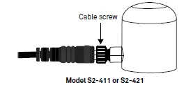
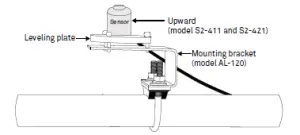 Figure 2 Upward-facing sensor installed on mounting post
2.1.2 DOWNWARD-FACING SENSOR
Each downward-facing Apogee NDVI or PRI sensor (S2-412 or S2-422) purchased from METER comes with an AM- 400 Adjustable Angle Mounting Bracket. The AM-400 can be mounted to either a horizontal or vertical post and can be adjusted to any angle between 0° (sensor pointed straight down) and 90° (sensor horizontal).
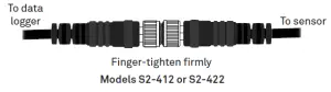
- Align the cable M8 connector with the sensor M8 connector and seat connectors fully.
- Tighten the cable screw until hand-tight (Figure 3). M8 connectors are easy to overtighten. Do not use pliers or other tools to tighten.
- Attach the sensor to the bracket using the nylon screw (Figure 4).
4. TROUBLESHOOTING
This troubleshooting section details possible major problems and their solutions. If theproblem is not listed or these solutions do not solve the issue, contact Customer Support.
Table 2 Troubleshooting
| Problem | Possible Solution |
| Sensor not responding | Check power to the sensor and logger.
Check sensor cable and stereo plug connector integrity. Check that the SDI-12 address of the sensor is 0 (factory default). Check this with ZENTRA Utility by going to Actions, select Digital sensor terminal, choose the port that sensor is on, and send the ?I! command to the sensor from the dropdown menu. |
| Sensor values are not reasonable | Check FOV to ensure the measurement area does not overlap a nonvegetated space.
Verify the sensor is not shaded. Verify the angle of sensors. |
| Cable or stereo plug connector failure | If the stereo plug connector is damaged or needs to be replaced, contact Customer Support for a replacement connector or splice kit.
If a cable is damaged refer to the METER wire-splicing guide for cable repair. |
It is recommended that Apogee NDVI and PRI sensors are returned for factory recalibration every 2 years. Visit Apogee repairs (apogeeinstruments.com/recalibration-and-repairs) orcontact Apogee Technical Support () for details.
3.3 SENSOR OUTPUTS
Each NDVI and PRI sensor generates multiple outputs when connected to a ZENTRA logger.The exact outputs will in part depend on how many and what type of sensors are attached to the data logger. All NDVI and PRI sensors are equipped with an internal tilt sensor. Theorientation of the NDVI or PRI sensor, and therefore the tilt sensor, will determine the output from each sensor.
3.3.1 UPWARD-FACING SENSOR OUTPUTS
For any hemispherical sensor oriented in the up-facing position, outputs will include the calibrated spectral irradiance values (in W × m–2 × nm–1) for both wavelengths (650 nm and 810 nm for NDVI; 570 and 532 nm for PRI), the sensor orientation angle (with 0 being a sensor oriented straight up toward the zenith), and α, where α is the ratio of 650 nm to 810 nm irradiance for NDVI sensors and 570 nm to 532 nm for PRI sensors as described in Equation 1.
3.3.2 DOWNWARD-FACING SENSOR OUTPUTS
When either hemispherical or field stop sensors are mounted in a downward-facing orientation, outputs include the calibrated spectral radiance (in W × m–2 × nm–1 × sr–1) of each band, the sensor orientation angle (with 0 being a sensor oriented striaght up toward the zenith), and the calculated NDVI value or PRI value (depending upon which sensors are used). If both upward-facing and downward-facing sensors are connected to the same ZENTRA logger, then α from the upward-facing sensor is combined with the spectral radiance values from the downward-facing sensor to calculate NDVI or PRI. If the upwardfacing and downward-facing sensors are connected to different data loggers, export data from ZENTRA Utility or ZENTRA Cloud and manually combine α from the upward-facing sensor with the spectral radiance values from the downward-facing sensor to calculate NDVI or PRI.
3.4 NDVI AND PRI DATA IN ZENTRA SOFTWARE
Cloud-connected ZENTRA data loggers with a current season pass subscription automatically upload data to ZENTRA Cloud for convenient viewing and downloading. Please go to the ZENTRA Cloud web app (metergroup.com/environment/zentra-cloud) or request a ZENTRA Cloud demo from METER sales for more information. ZENTRA Cloud provides calibrated radiance and irradiance data from both wavebands for all time periods but only calculates NDVI and PRI from sunlit periods, as both spectral reflectance indices are meaningless and highly unstable at low solar radiation levels.
METER ZENTRA series data loggers can also be configured and downloaded using the ZENTRA Utility desktop app and ZENTRA Utility Mobile app for iOS® and Android® handheld devices. As with ZENTRA Cloud, ZENTRA Utility data downloads provide calibrated radiance and irradiance data from both wavebands for all time periods but only calculates NDVI and PRI from sunlit periods, as the values are meaningless and highly unstable at low solar radiation levels.
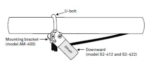
Figure 4 Downward-facing sensor installed on mounting post4. Attach the mounting bracket either to a horizontal arm (Figure 4) or vertical post using the included U-bolt.5. Tighten the U-bolt.6. Orient the sensor to the proper angle to achieve the desired fi eld of view ( FOV) and tighten screws to hold in place.Use the Apogee IRR Calculators (apogeeinstruments.com/irr-calculators) to help calculate FOV.v
2.2 CONNECT TO METER ZENTRA SERIES LOGGER
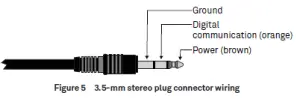
Apogee NDVI and PRI sensors are preconfigured by METER and work seamlessly with METER ZENTRA series data loggers. The sensors come with a 3.5-mm stereo plug connector(Figure 5) to facilitate easy connection with the data loggers. Apogee sensors come standard with a 5-m cable.
INSTALLATION
Check the METER download webpage for the most recent data logger firmware. Logger configuration may be done using either ZENTRA Utility (desktop and mobile application) or ZENTRA Cloud (web-based application for cell-enabled ZENTRA data loggers).
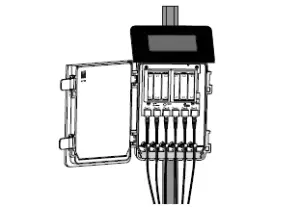
- Plug the stereo plug connector into one of the sensor ports on the logger (Figure 6).
- Connect to the data logger via ZENTRA Utility with a laptop and USB cable or ZENTRA Utility Mobile app with a mobile device supporting Bluetooth® communication.
- Use ZENTRA Utility to scan the ports and make sure the sensors were properly identifi ed by the logger and are reading properly. METER data loggers should automatically recognize the Apogee sensor.
- Use ZENTRA Utility to set the measurement interval.
- Use ZENTRA Utility to confi gure communication settings for data transfer to ZENTRA Cloud. Sensor data can be downloaded from METER data loggers using either ZENTRA Utility orZENTRA Cloud. Refer to the logger user manual for more information.
3. DATA INTERPRETATION
This section provides information on how to properly understand NDVI and PRI data, as recorded by ZENTRA data loggers.
3.1 NDVI AND PRI DATA HANDLING
METER data loggers measure the Apogee NDVI and PRI sensors once every minute and return the average of the 1-min data across the chosen measurement interval.
3.2 REFLECTANCE FROM PAIRED SENSORS
Paired upward-facing and downward-facing sensors are needed to collect data for calculating reflectance, to account for temporal variability in incoming radiation conditions. In cases where multiple downward-facing sensors are deployed within close proximity to each other, only one upward-facing sensor is necessary. The measurements from the single upward-facing sensor can be combined with measurements from each of the downwardfacing sensors to calculate reflectances. With ZENTRA data loggers, irradiance from a single S2-411 or S2-421 upward-facing sensor will be used to calculate NDVI or PRI with all S2- 412 or S2-422 downward-facing sensors connected to the same logger. In the event that upward-facing measurements are not available, rearrangement of thevegetation index equations allows for a rough approximation of NDVI using a default αvalue. The following derivation is for NDVI, but similar equations apply to the PRI. If Rn is the reflected NIR radiation from the canopy, Rr is the reflected red radiation, In is the incident NIR, and Ir is the incident red, then
NDVI = Equation 1Rn / In − Rr / IrRn / In + Rr / Ir=Ir / In ( )Rn − RrRn / In ( )Rr + Rr=αRn − RrαRn + Rr
where α = Ir / In.
 report this ad
Equation 1 allows the computation of NDVI from just the downward-facing measurements if the ratio of red to NIR spectral irradiance (α) is known. An upward-facing sensor should always be used to calculate reflectance. However, if no upward-facing NDVI sensor is present, a default α of 1.4 can be used to calculate NDVI from all downward-facing sensors on that logger, although it will result in reduced precision under changing sky conditions. Using a default α value for PRI calculations is not recommended because the additional error resulting from a default α value compromises the usefulness of PRI.
Read More About This Manual & Download PDF:
References
[xyz-ips snippet=”download-snippet”]