Metra POWERSPORTS MPS-DSP-RC1 Polaris Ride Command DSP Harness
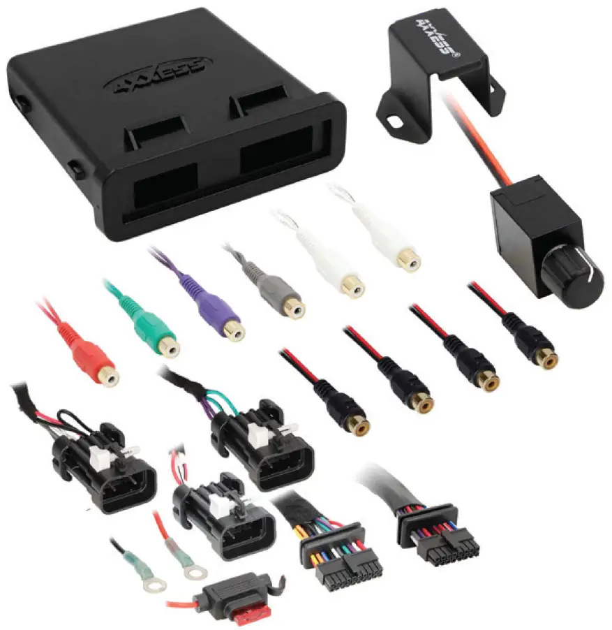
INTERFACE COMPONENTS
- MPS-DSPX-RC1 circuit board
- MPS-DSPX-RC1 harness (with gaskets)
- MPS-DSPX-RC1 enclosure (w/case, cap and O-ring)
INTERFACE FEATURES
- Water resistant enclosure with zip tie mounts included
- 31 Band graphic EQ
- Prewired input harness, 10 individually assignable outputs
- Independent equalization on each of the 10 outputs
- Independent high pass, low pass, and bandpass filters
- Each channel can be delayed independently up to 10ms
- Easy behind the Ride Command installation
- Designed for Polaris Ride Command Systems
- Clipping detection and limiting circuits
- Bass knob included
- Settings adjusted via Bluetooth® in a smart device application (tablet or mobile phone), compatible with both Android and Apple devices
- Read, write, and store configurations for future recall
- Password protect feature available in the mobile app
- Micro-B USB updatable
TOOLS & INSTALLATION ACCESSORIES REQUIRED
- Crimping tool and connectors, or solder gun, solder, and heat shrink
- Tape
- Wire Cutter
- Zip Ties
- Multimeter
PREFACE
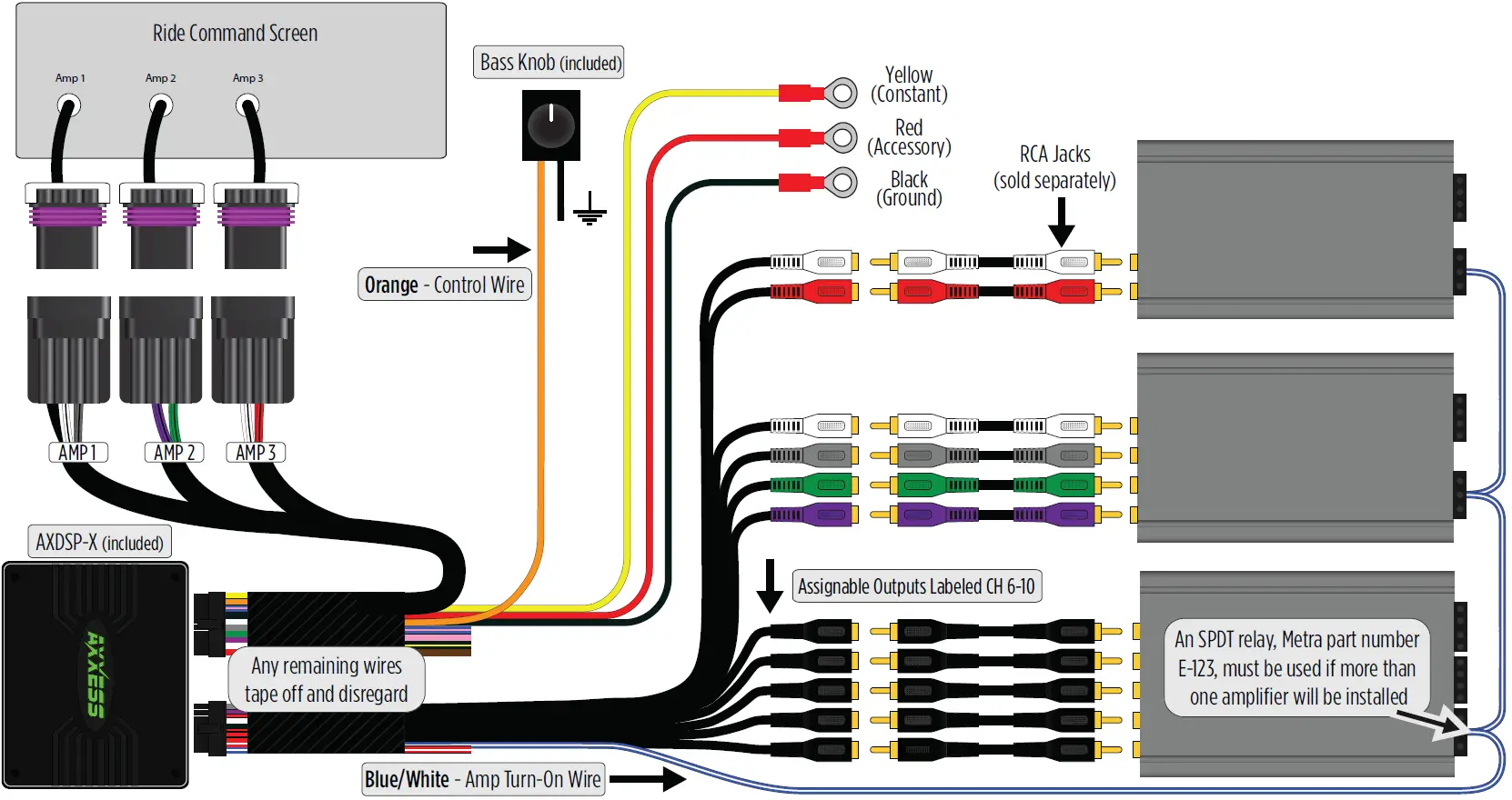
The MPS-DSPX-RC1 is designed specially for the Polaris Ride Command system. The input of the DSPX harness is prewired to plug directly into the Amp 1, Amp 2, and Amp 3 harnesses behind the RC screen. The MPS-DSPX-RC1 offers a Differential Balanced input as well as independent level control on the outputs of each channel. Independent volume control is important for the AMP 3 factory plug. AMP 3’s output is not adjustable through the ride command screen. The AX-DSP-XL app offers the ability to control the output level of your subwoofer. The kit also includes a remote mounted bassknob that offers additional output control for your aftermarket subs. Another common problem with adding aftermarket amps to the RC system is “turn on pops”. Through the APP you can delay the remote output turn on up to 10 seconds eliminating the turn on/off pops you can get with the other products.
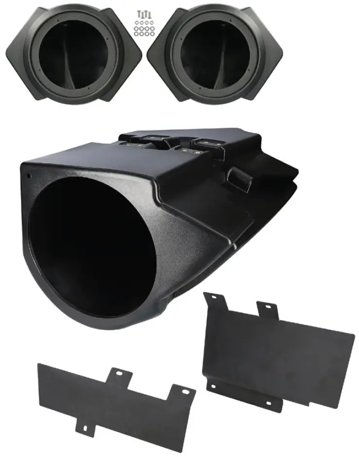
To complete your new system we recommend our MPS-RZKIT.The MPS-RZKIT is a 10” Subwoofer and Speaker Pod combo kit with amplifier mount brackets included.The MPS-RZKIT fits 2014-Up Polaris RZR models.
PINOUT
INSTALLATION
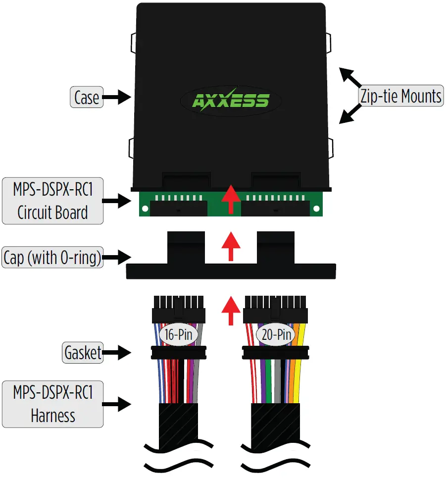
- With the arrow stamped onto the cap facing upwards, push the 16-pin connector from the MPS-DSPX-RC1 harness into the left side of the cap. The locking clip on the connector should face upward. Make sure the gasket is seating properly in the cap.
- With the arrow stamped onto the cap still facing upwards, push the 20-pin connector from the MPS-DSPX-RC1 harness into the right side of the cap. The locking clip on the connector should face upward. Make sure the gasket is seating properly in the cap.
- Plug the 16-pin and 20-pin connectors from the MPS-DSPX-RC1 harness into the MPS-DSPX-RC1 circuit board.
- Slide the assembly into the case, then click it shut. Zip-tie the enclosure to a secure location to secure it. Make sure the logo is facing up to further ensure that no outside elements can enter the enclosure.
- Gain access to the rear of your Ride Command Screen. Refer to your Service manual for instructions. Each Audio Amp connector is located in the upper dash compartment. Match up Amp1, Amp2, and Amp3 connectors to each other and plug in.
- Download and install the AX-DSP-XL app from the Google Play Store or Apple App Store.
- Open the app and follow the instructions on the Bluetooth Connection tab to pair the mobile device to the MPS-DSPX-RC1.
- Scroll to the Configuration tab then select Polaris as the vehicle type. Then select your model. Keep without OE amplifier selected regardless of the OE system type.
- Connect the amp turn-on wire from the MPS-DSPX-RC1 to your aftermarket amplifiers.
- Adjust the DSP settings in the app as desired. Refer to the instructions starting on (page 6) for an explanation of each tab in the app.
RIDE COMMAND CONNECTION DIAGRAM
QUICK SETUP GUIDE
DSP Setup & Controls
The MPS-DSPX-RC1 uses the Axxess DSP XL application to control and setup your DSP. Only items pertaining to the MPS-DSPX-RC1 will be shown.
Download and install the AXDSP-XL app from the Google Play Store or Apple App Store.Below are the quick steps to get your MPS-DSPX-RC1 system configured and playing. The AXDSP-XL app is powerful and offers many features.To find out more about these advanced feature review the Advanced features page.Open the app then select the Bluetooth Connection tab.
With your MPS-DSPX-RC1 powered on, select the SCAN button. The app will start searching for available DSP’s. Once found select your device. In the top left corner of the app you will see it change from Not Connected to Connected.
From the configurations page you should first test your system to make sure everything is connected properly after the DSP. To test your setup select the IDENTIFY button. This will play a chime thought your setup to confirm your system is ready to pass audio.

Next select your VEHICLE TYPEThe MPS-DSPX-RC1 will be set to Polaris for the Make. Next, select your Model, RZR or General. If you have a Ranger select General as your model, keep “Without OE Amp” selected, then select Apply.
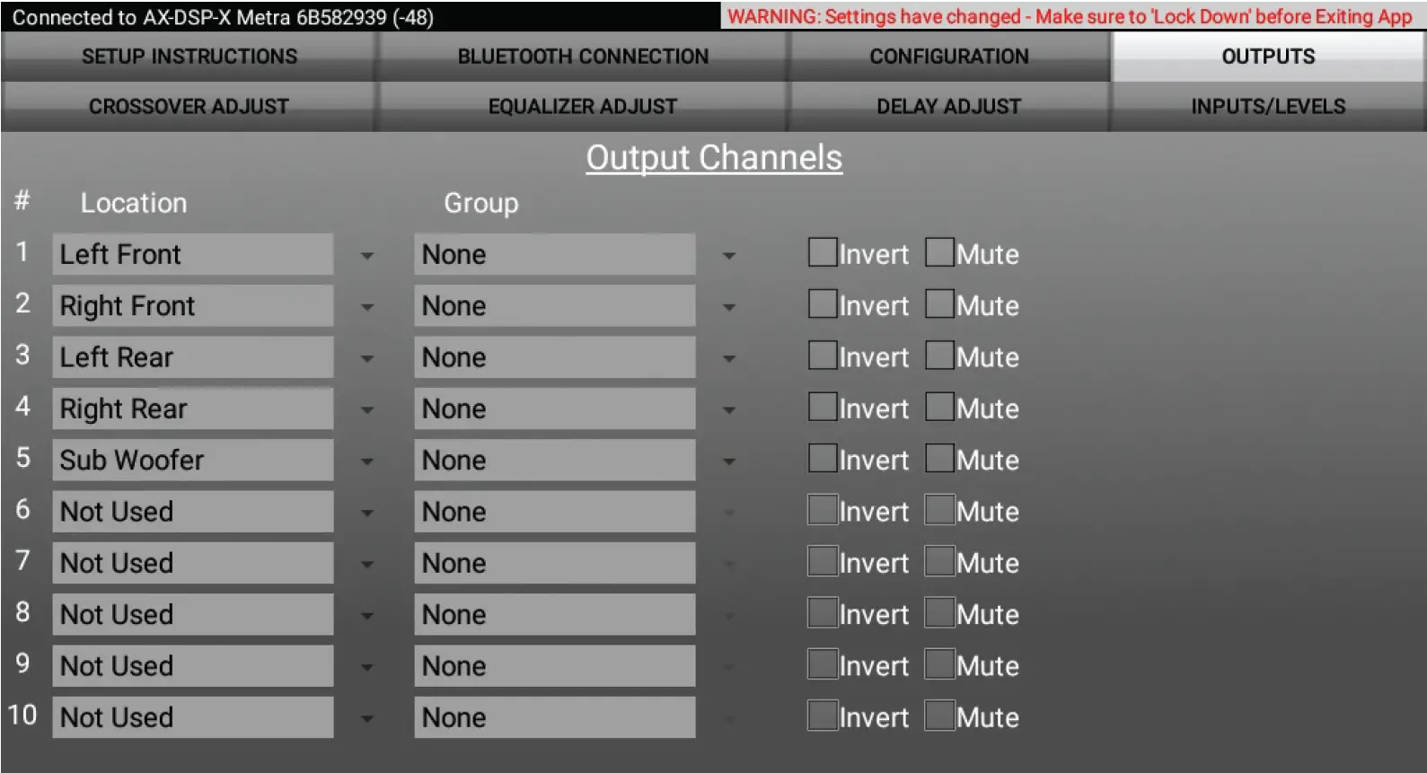
Next Select the OUTPUTS tab – This screen is where you setup your speaker’s output channels. Under the GROUP menu, select the first drop down arrow to the right of the word NONE. Select the name from the dropdown menu that matches the location listed on the far left of the screen.Example: #1 – Location – Left Front, under the Groups dropdown menu select Left Front.
- Location – Location of speaker.
- Group – Used to join channels together for simple equalization. Example: left front woofer/midrange and left front tweeter will be considered simply left front. The letter M denotes the speaker assigned as the master speaker.
- Invert – Will invert the phase of the speaker.
- Mute – Will mute desired channel(s) for tuning individual channels.
Next Screen will allow you to set your crossover points, filter type, and slope. If you would like to pass full frequency range to your amps set all filters to High Pass and drag the slider all the way to the left making sure the entire frequency bar is green.
- Selecting High Pass and Low Pass will provide one crossover frequency adjustment. Band Pass should only be chosen if installing just front speakers, with one dedicated amp for the woofers/mids, a second dedicated amp for the tweeters, along with a subwoofer.
- If you have a specific frequency you would like, select the number above the slider and enter in your exact frequency.
- Select the desired crossover slope, 24db, 36db, or 48 db.

The Equalizer Adjustment tab will allow you to independently set your preferred audio curve for each channel. It is recommended that a Real Time Analyzer (RTA) be used to adjust these settings. If you choose to leave your EQ settings flat is will not affect the output signal. The purpose of the EQ setting is to offer the user the ability to tune the system to their listening style.
- The front, rear, and sub channels can be adjusted independently within this tab with 31 bands of equalization available.
- The Gain slider on the far left is for the channel selected.
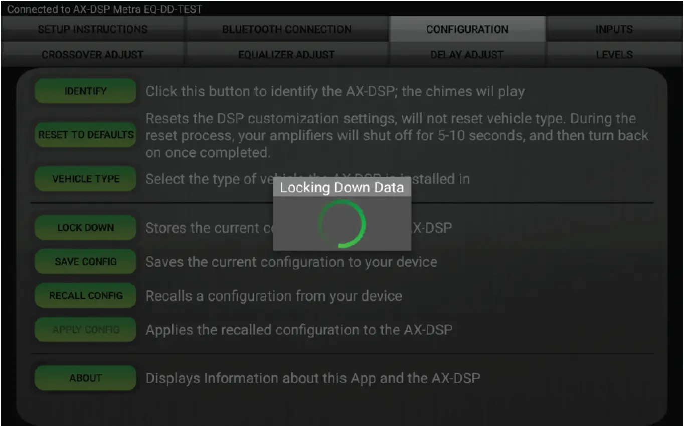
The final step to getting your MPS-DSPX-RC1 setup is to save all your settings to the DSP. To do this select your CONFIGURATIONS tab and select LOCK DOWN. This will write all your setting to the DSP and save them.Note: If you turn the ignition off or close the app before LOCKING DOWN all your information will be lost and you will need to go through the setup steps again.
ADVANCED DSP FEATURES & CONTROL OPTIONS
Configuration
- Identify – Click this button to confirm that the interface is connected properly. If so, a chime will be heard from the front left speaker*.* Only installations where the interface is connected to a front left speaker.
- Reset to Defaults – Resets the interface to factory settings. During the reset process the amplifiers will shut off for 5-10 seconds.
- Vehicle Type – Select the vehicle type from the drop down box, select either Without OE Amplifier or With OE Amplifier, then click the apply button.
- Lock Down – Click this button to save the selected settings. Attention! This button must be selected before closing the app or cycling the key otherwise all settings will be lost.
- Save Configuration – Saves the current configuration to the mobile device.
- Recall Configuration – Recalls a configuration from the mobile device.
- About – Displays information about the app, vehicle, interface and mobile device.
- Set Password – Assign a 4-digit password to lock the interface. If no password is desired, use “0000”. This will clear out any currently set password. It is not necessary to lock down the interface when setting a password.Note: A 4-digit only password must be chosen otherwise the interface will show “password not valid for this device”.
- Clear Phones – Clears phones paired from memory.
Delay Adjust
- Allows a delay of each channel. If a delay is desired, first measure the distance (in inches) from each speaker to the listening position, then enter those values to the corresponding speaker. Add (in inches) to the desired speaker to delay it.
Inputs/Levels
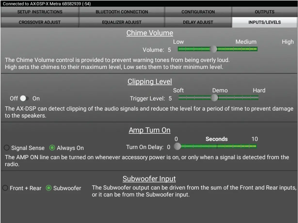
- Clipping Level – Use this feature to protect sensitive speakers like tweeters from being driven past their capabilities. If the output signal of the DSP clips the audio will be reduced by 20dB. Turning down the stereo will allow the audio to come back at a normal level. The sensitivity of this feature can be adjusted to the listening preference of the user.
- Chime Volume – Not applicable in this application.
- Amp Turn On
- Signal Sense – Will turn the amplifier on when an audio signal is detected, and keep on for 10 seconds past the last signal. This ensures the amplifier doesn’t shut off between tracks.
- Always On – Will keep the amplifiers on as long as they is cycled on.
- Turn on Delay – Can be used to delay amp turn-on to avoid turn-on pops.
- Subwoofer Input – For selecting either a dedicated subwoofer input or summed from the front and rear inputs.
DON’T FORGET TO LOCK DOWN!!!
SPECIFICATIONS
- Input Impedance – 1M Ohm
- Input Channels – 6 High/Low level Selectable
- Input Options – High Level or Low Level
- Input Type – Differential-Balanced
- Input Voltage
- High Level Range – 0 – 28v Peak to Peak
- Low Level Range – 0 – 4.9v Peak to Peak
- Ouput Channels – 10
- Output Voltage – Up to 5v RMS
- Output Impedance – 50 Ohms
- Equalizer Type – 31 Band Graphic EQ, +/- 10dB
- THD – <0.03%
- Frequency Response – 20Hz – 20kHz
- Crossover – 3-Way LPF, BPF, HPF THP per channel
- Crossover Type – Linkwitz-Riley 24db, 36db, or 48 db
- Sampling – 48kHz
- S/N Ratio – 105dB @ 5V RM
General
- Operating Voltage – 10 – 16VDC
- Standby Current Draw – ~7mA
- Operation Current Draw – ~150mA
- Adjustments/Controls – Application via Bluetooth
- Remote Output – 12VDC, Signal Sense or with Ignition
Having difficulties? We’re here to help.
Contact our Tech Support line at:1-800-253-TECHOr via email at:[email protected]
Tech Support Hours (Eastern Standard Time)Monday – Friday: 9:00 AM – 7:00 PMSaturday: 10:00 AM – 7:00 PMSunday: 10:00 AM – 4:00 PM
report this ad![]()
References
[xyz-ips snippet=”download-snippet”]