![]()
95-9405BINSTALLATION INSTRUCTIONS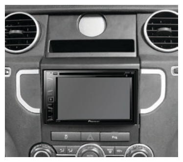 Land Rover LR4 2010-2011Visit MetraOnline.com for more detailed information about the product and up-to-date vehicle specific applications
KIT FEATURES
- ISO DDIN radio provision
- Includes all necessary data interfaces, wiring harnesses, and antenna adapters, for a complete installation
- Includes provisions for the factory clock
- Painted black to match the factory dash
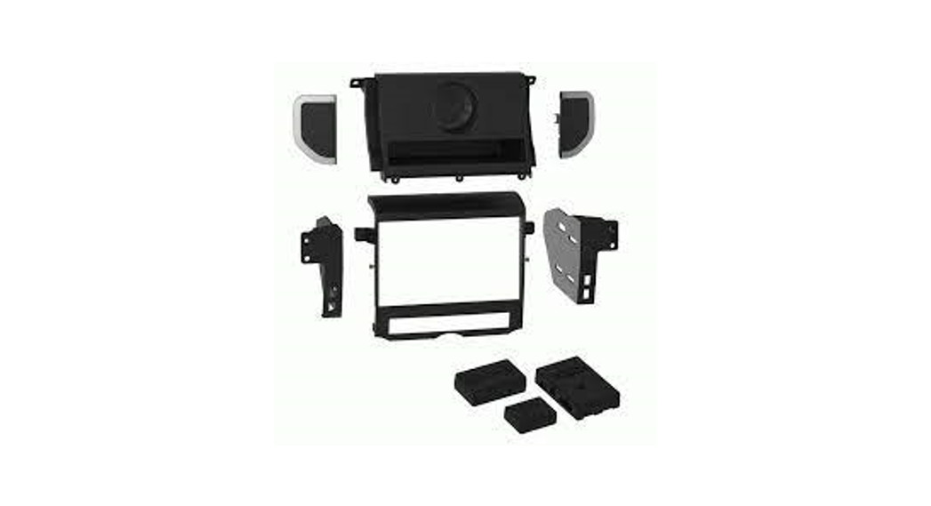
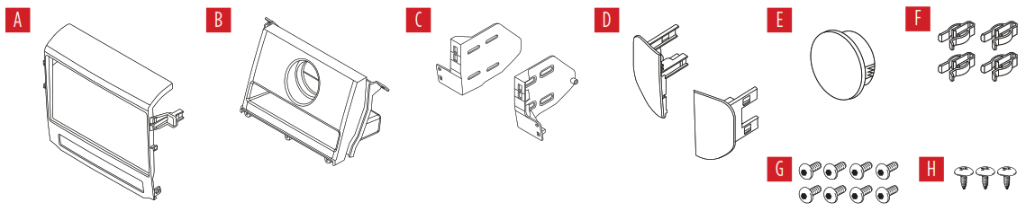
KIT COMPONENTS
- A) Radio trim panel (bottom)
- B) Radio trim panel (top)
- C) Radio brackets
- D) Trim wings
- E) Clock blank-out panel
- F) Panel clips (4)
- G) Radio screws (8)
- H) Pan-head screws (3)
- I) ASWC-1 interface and wiring harness (not shown)
- J) Axxess interface and wiring harness (not shown)
- K) Amplifier interface (not shown)
- L) Antenna adapter (not shown)
WIRING & ANTENNA CONNECTIONSWiring Harness: Included with kitAntenna Adapter: Included with kitSteering Wheel Control Interface: Included with kit
TOOLS REQUIRED
- Cutting tool
- Panel removal tool
- Phillips screwdriver
- 3mm Allen screwdriver
Attention! Let the vehicle sit with the key out of the ignition for a few minutes before removing the factory radio. When testing the aftermarket equipment, ensure that all factory equipment is connected before cycling the key to ignition.
Metra. The World’s Best Kits. ®MetraOnline.com© COPYRIGHT 2019 METRA ELECTRONICS CORPORATIONREV. 2/25/21 INST95-9405B
DASH DISASSEMBLY
1. Engage the parking brake. Place the gear selector in neutral, then pull the knob from the gear selector.
Note: Some force may be required to complete this step.

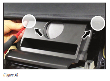
2. Unclip and remove the cup holder, then remove (2) the screws exposed. (Figure A)
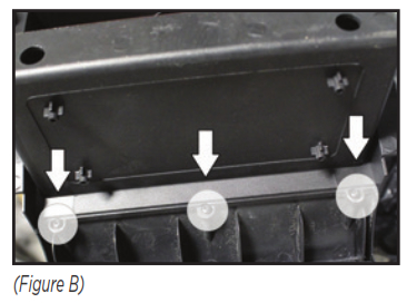
 3. Pull up and back to unclip and loosen the top trim from the center console. The trim needs to be moved just a few inches away from the bottom of the dashboard area to allow radio removal. (Figure B)
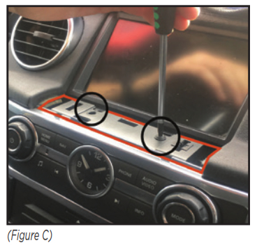
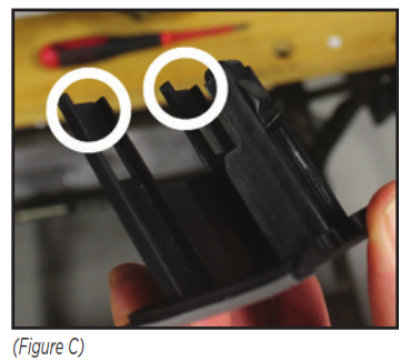
4. Unclip and remove the small trim panel below the display screen. Remove (2) screws exposed. (Figure C)

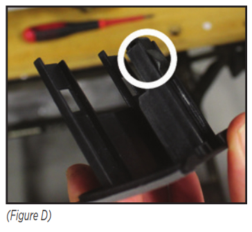
5. Unclip and remove the silver trim surrounding the clock and radio controls. (Figure D)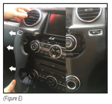 6. Pull up and back to unclip the panel to the left side of the radio. Unplug the Start/Stop button. Likewise for the right-side panel, less the Start/Stop button. (Figure E)
7. Unclip and remove the clock and radio control panel. Remove and retain the (4) clips attached to the panel to be re-used in Kit Preparation.
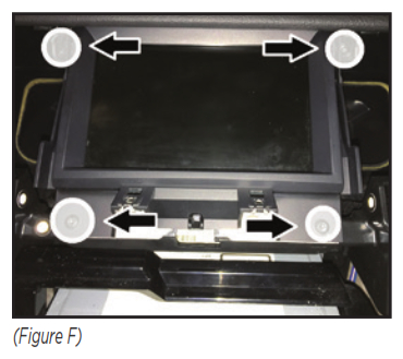
8. Remove (4) screws securing the display screen, then unclip, unplug, and remove the screen. (Figure F)

9. Remove (6) screws securing the climate control/hazard-switch/disc-player assembly, then unclip, unplug, and remove the entire assembly. (Figure G)
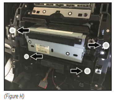
10. Remove (4) screws securing the radio to the dash. Slide the radio out, then unplug and remove the radio. Figure H)
KIT PREPARATION
Climate Control Modification1. Remove the climate control and hazard switch from to the climate-control/ hazard-switch/disc-player assembly.
2. Reconnect and reinstall the climate control and hazard-switch assembly back to the vehicle.
Sub-Dash ModificationAttention! The vehicle cannot be restored back to the factory after performing the following step.
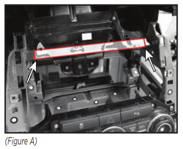
3. Cut the shaded area in the sub-dash to allow room for the aftermarket radio. (Figure A)
Housing Assembly4. Attach the top and bottom radio trim panels together using the (3) pan-head screws provided. (Figure B5. Clip in either the factory clock or clock blank-out panel to the assembly.6. Attach (2) of the panel clips provided to the completed radio trim panel assembly.
Trim Wing Preparation7. Attach the (4) factory metal panel clips removed in step 7 from Dash Disassembly to the trim wings. (Figure C)
8. Attach (2) of the panel clips provided to the trim wings. (Figure D)
KIT ASSEMBLY

1. Secure the radio brackets to the radio using either the screws supplied with the radio or the radio screws provided. (Figure A)
AXXESS INTERFACE INSTALLATION
INTERFACE FEATURES
- Provides NAV outputs (parking brake, reverse, speed sense)
- Retains audio/phone† controls on the steering wheel
- Retains balance
- Micro-B USB updatable† Radio dependent
INTERFACE COMPONENTS
- 9405 interface
- 9405 harness
- 9405 amplifier interface
- ASWC-1 interface
- ASWC-1 harness
- Female 3.5mm connector with stripped leads
TOOLS REQUIRED
- Crimping tool and connectors, or solder gun, solder, and heat shrink
- Tape
- Wirecutter
- Zip ties
CONNECTIONS
From the 9405 harnesses to the aftermarket radio:
- Connect the Black wire to the ground wire.
- Connect the Yellow wire to the battery wire.
- Connect the Red wire to the accessory wire.Note: There will an accessory wire from the ASWC-1 harness to connect as well.
- Connect the Blue wire to the power antenna wire.
- If the aftermarket radio has an illumination wire, connect the Orange wire to it.The following (3) wires are only for multimedia/navigation radios that require these wires.
- Connect the Blue/Pink wire to the speed sense wire.
- Connect the Green/Purple wire to the reverse wire.
- Connect the Light Green wire to the parking brake wire.
- Connect the Red and White RCA jacks to the full range amplifier output jacks.
From the ASWC-1 harness to the aftermarket radio:This harness is to be used if the vehicle is equipped with steering wheel controls.
- Connect the Red wire to the accessory wire.
- For the radios listed below: Connect the female 3.5mm connector with stripped leads, to the male 3.5mm SWC jack from the ASWC-1 harness. Any remaining wires tape off and disregard:
- Eclipse: Connect the steering wheel control wire, normally Brown, to the Brown/White wire from the connector. Then connect the remaining steering wheel control wire, normally Brown/White, to the Brown wire from the connector.
- Metra OE: Connect the steering wheel control Key 1 wire (Gray) to the Brown wire.
- Kenwood or select JVC with a steering wheel control wire: Connect the Blue/Yellow wire to the Brown wire.Note: If the Kenwood radio auto-detects as a JVC, manually set the radio type to Kenwood. Refer to the Changing Radio Type document available at axxessinterfaces.com/product/ASWC-1.
- XITE: Connect the steering wheel control SWC-2 wire from the radio to the Brown wire.
- Parrot Asteroid Smart or Tablet: Connect the 3.5mm jack into the AX-SWC-PARROT (sold separately). Then connect the 4-pin connector from the AX-SWC-PARROT to the radio.Note: The radio must have rev. 2.1.4 or higher software.
- Universal “2 or 3 wire” radio: Connect the steering wheel control wire, referred to as Key-A or SWC-1, to the Brown wire from the connector. Then connect the remaining steering wheel control wire, referred to as Key-B or SWC-2, to the Brown/White wire from the connector. If the radio comes with a third wire for the ground, disregard this wire.Note: After the interface has been programmed to the vehicle, refer to the manual provided with the radio for assigning the SWC buttons. Contact the radio manufacturer for more information.
- For all other radios: Connect the 3.5mm jack from the ASWC-1 harness into the jack from the aftermarket radio designated for an external steering wheel control interface. Please refer to the aftermarket radios manual if in doubt as to where the 3.5mm jack should connect to.
INSTALLATION
With the key in the off position:
- Connect the 9405 harnesses to the 9405 interfaces.
- Connect the 9405 harnesses to the 9405 amplifier interfaces.
- Remove the dust cover from the fiber optic port in the 9405 amplifier interfaces.
- Connect the factory fiber optic cable into the 9405 amplifier interfaces.
- Connect the 9405 harnesses to the wiring harness in the vehicle.
- Connect the ASWC-1 harness to the ASWC-1 interface, and then to the 9405 interfaces.
- Locate the factory antenna connector in the dash and complete all necessary connections to the radio. Use the antenna adapter provided to adapt the factory antenna connector to the aftermarket radio.Attention! If retaining steering wheel controls, ensure that the SWC jack/wire is connected to the radio before proceeding. If this step is skipped, the interface will need to be reset for the steering wheel controls to function.
PROGRAMMING
- Press and hold the Volume Up button on the steering wheel.
- Turn the ignition on, the L.E.D. in the ASWC-1 interface will start flashing rapidly, which means the ASWC-1 interface is looking for the vehicle and the radio.
- After a few seconds, the L.E.D. should stop flashing rapidly, then go out for approximately 2 seconds.
- After 2 seconds there will be a series of 7 Green flashes, some short, and some long. The long flashes represent the wires that are connected from the vehicle to the ASWC-1 interface. The 3rd, 4th, 5th, and 6th flashes should be longer.
- The L.E.D. will pause for another 2 seconds, then flash Red up to 18 times depending on which radio is connected to the ASWC-1 interface. Refer to the L.E.D. Feedback section for more information.
- This is the end of the auto-detection stage. If the ASWC-1 interface detected the vehicle and radio successfully, the L.E.D. will light up solid. If not, refer to the troubleshooting documents available at axxessinterfaces.com/product/ASWC-1.
- Test all functions of the installation for proper operation before reassembling the dash. Refer to the ASWC-1 Steering Wheel Control documents available at axxessinterfaces.com/product/ASWC-1 for customizing the buttons, if so desired.Note: Only the Land Rover logo will be displayed on the factory display screen.
L.E.D. FeedbackThe (18) Red L.E.D. flashes represent the brand of radio the ASWC-1 interface believes it is connected to. Each flash count represents a different radio Manufacturer. For example, if you are installing a JVC radio, the ASWC-1 interface will flash Red (5) times, then stop. Following is a legend that explains which radio manufacturer corresponds to the flash count provided.
L.E.D. feedback legend
| Flash Count | Radio | Flash Count | Radio |
| 1 | Eclipse (type 1) † Kenwood ‡ Clarion (type 1) † Sony / Dual
JVC Pioneer / Jensen Alpine * Visteon Valor |
10 | Clarion (type 2) † Metra OE
Eclipse (type 2) † LG Parrot ** XITE Philips TBA JBL |
| 2 | 11 | ||
| 3 | 12 | ||
| 4 | 13 | ||
| 5 | 14 | ||
| 6 | 15 | ||
| 7 | 16 | ||
| 8 | 17 | ||
| 9 | 18 |
* If the ASWC-1 interface flashes Red (7) times, and an Alpine radio is not installed, that means an open connection. Verify that the 3.5mm jack is connected to the correct steering wheel jack/wire in the radio.
** The AX-SWC-PARROT is required (sold separately). Also, the software in the radio must be rev. 2.1.4 or higher.
† If a Clarion radio is installed and the steering wheel controls do not function, change the radio type to the opposite Clarion radio type; likewise for Eclipse. Refer to the Changing Radio Type document available at xxessinterfaces.com/product/ASWC-1.
‡ If a Kenwood radio is installed and the L.E.D. feedback comes back showing as a JVC radio, change the radio type to Kenwood. Refer to the Changing Radio Type document available at axxessinterfaces.com/product/ASWC-1.
FINAL ASSEMBLY
- Secure the radio assembly to the dash using (2) of the factory screws removed in step 10 from Dash Disassembly.
- Clip the radio trim panel to the dash, then secure it using (2) of the factory screws removed in step 8 from Dash Disassembly. (Figure A)
- Clip the left and right radio panels back to the dash. Ensure to reconnect the Start/Stop button.
- Clip-in the trim wings to the left and right sides of the radio.
- Clip-in the top trim back to the center console, then secure the panel using the (2) factory screws.
- Clip the cup holder back into the center console.
- Push the knob back onto the gear selector to complete the installation.

If you are having difficulties with the installation of this product, contact our Tech Support line either by phone at 1-800-253-TECH, or email at [email protected]. Before doing so, look over the instruction booklet a second time and ensure that the installation was performed exactly as the instruction booklet is stated. Have the vehicle apart and ready to perform troubleshooting steps before contacting Metra/Axxess Tech Support.
![]() KNOWLEDGE IS POWEREnhance your installation and fabrication skills by enrolling in the most recognized and respected mobile electronics school in our industry. Log onto www.installerinstitute.com or call 800-354-6782 for more information and take steps toward a better tomorrow.
KNOWLEDGE IS POWEREnhance your installation and fabrication skills by enrolling in the most recognized and respected mobile electronics school in our industry. Log onto www.installerinstitute.com or call 800-354-6782 for more information and take steps toward a better tomorrow.
![]() Metra recommends MECP certified technicians
Metra recommends MECP certified technicians
References
[xyz-ips snippet=”download-snippet”]