![]() 99-6537BINSTALLATION INSTRUCTIONS
99-6537BINSTALLATION INSTRUCTIONS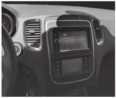
Dodge Durango 2014-2017Visit MetraOnline.com for more detailed information about the product and up-to-date vehicle-specific applications.
KIT FEATURES
- ISO DIN radio provision with pocket
- ISO DDIN radio provision
- Touchscreen display for climate and personalization features
- Painted Black
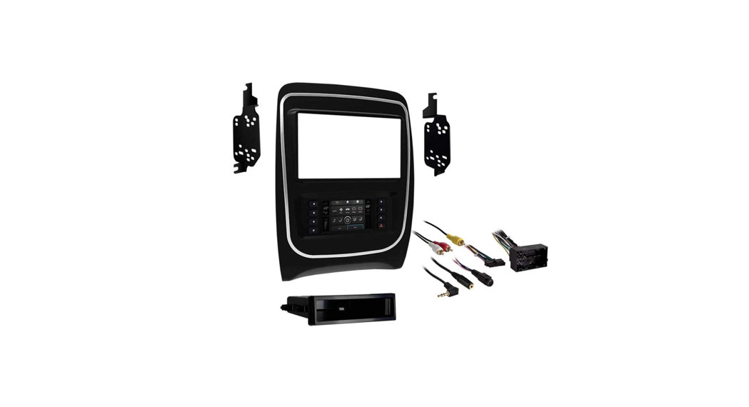
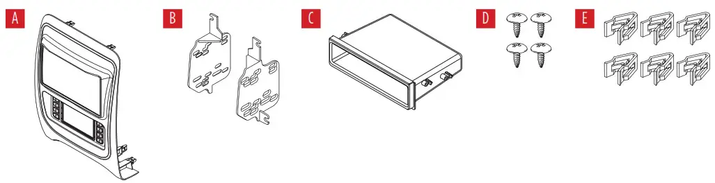
KIT COMPONENTS
- A) Radio trim panel with a touchscreen display
- B) Radio brackets
- C) Pocket
- D) (4) #8 x 3/8” Phillips screws
- E) (6) Panel clips
- F) Antenna adapter (not shown)
WIRING & ANTENNA CONNECTIONS
Wiring Harness: Axxess interface built into the touchscreenAntenna Adapter: Included with the kitSteering wheel control interface: Included with the kit
TOOLS REQUIRED
- Panel removal tool
- Phillips screwdriver
- 9/32” socket wrench
- 5.5mm socket wrench
Attention! Let the vehicle sit with the key out of the ignition for a few minutes before removing the factory radio. When testing the aftermarket equipment, ensure that all factory equipment is connected before cycling the key to ignition.
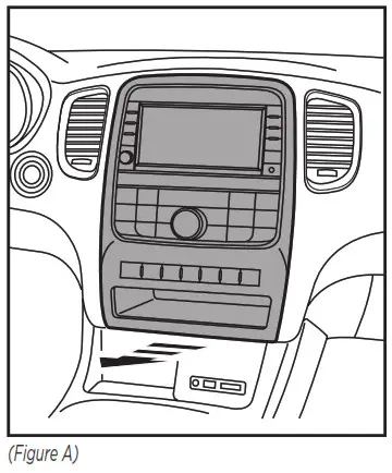
DASH DISASSEMBLY
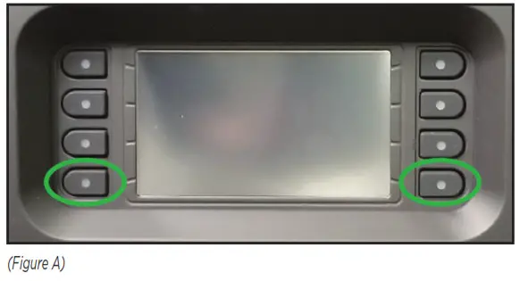
- Unclip and remove the radio/climate control panel. (Figure A)

- Remove the (4) 9/32 screws securing the radio/display screen, and then unplug and remove.
- Remove the (3) 5.5mm screws securing the black control module in the sub dash, and then relocate lower to allow clearance for the aftermarket radio.
KIT PREPARATION
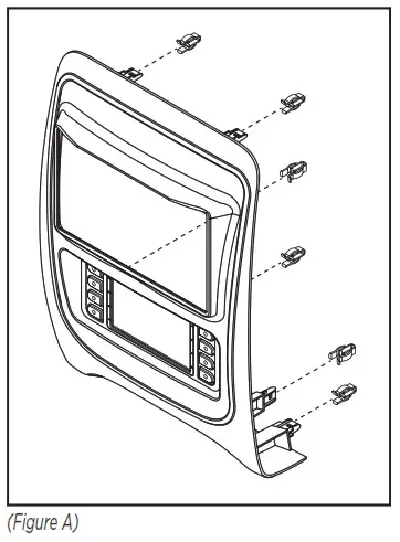
To the 99-6537CH radio trim panel:
- Attach the (6) panel clips provided. (Figure A)
KIT ASSEMBLY
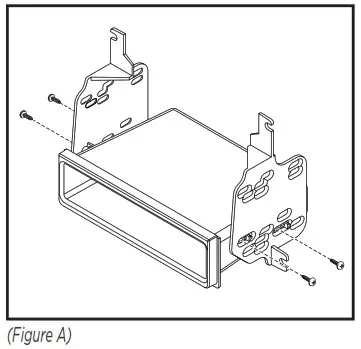
ISO DIN radio provision with pocket
- Attach the pocket to the radio brackets using the (4) #8 x 3/8” Phillips screws provided. (Figure A)
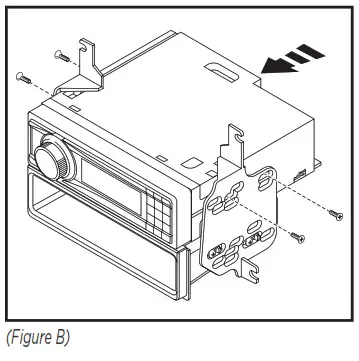
- Remove the metal DIN sleeve and trim ring from the aftermarket radio.
- Slide the radio into the bracket/pocket assembly, then secure it using the screws supplied with the radio. (Figure B)
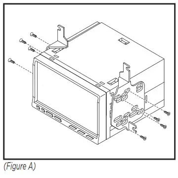
ISO DDIN radio provision
- Attach the radio brackets to the radio using the screws supplied with the radio. (Figure A)
AXXESS INTERFACE INSTALLATION
INTERFACE FEATURES
- Provides accessory power (12-volt 10-amp)
- Retains R.A.P. (retained accessory power)
- Provides NAV outputs (parking brake, reverse, speed sense)
- Retains audio controls on the steering wheel
- Retains safety chimes
- Retains the factory backup camera
- Retains the factory AUX-IN jack
- Retains balance and fade*
- Micro-B USB updatable* Non-amplified models only.
INTERFACE COMPONENTS
- Axxess interface (built into the touchscreen display)
- 6537 harness
- 16-pin harness with stripped leads
- 4-pin harness with yellow RCA jacks
- Hazard harness
- Female 3.5mm connector with stripped leads
TOOLS REQUIRED
- Crimping tool and connectors, or solder gun, solder, and heat shrink
- Tape
- Wirecutter
- Zip ties
- Small flat-blade screwdriver
CONNECTIONS
Attention! This interface will work with models that are either non-amplified or amplified. Please follow the instructions carefully for your model vehicle. Failure to do so will result in either no sound or low sound. If you are unsure if your vehicle is factory amplified or not, please contact your local dealership. For models without a factory amplifier:From the 16-pin harness with stripped leads to the aftermarket radio:
- Connect the Red wire to the accessory wire.
- If the aftermarket radio has an illumination wire, connect the Orange/White wire to it.
- Connect the Green wire to the left rear positive speaker output.
- Connect the Green/Black wire to the left rear negative speaker output.
- Connect the Purple wire to the right rear positive speaker output.
- Connect the Purple/Black wire to the right rear negative output.
- Tape off and disregard the following (6) wires, they will not be used in this application.Blue/White, Brown, Gray, Gray/Black, White, White/Black
The following (3) wires are only for multimedia/navigation radios that require these wires.
- Connect the Blue/Pink wire to the VSS/speed sense wire.
- Connect the Green/Purple wire to the reverse wire.
- Connect the Light Green wire to the parking brake wire.
From the 6537 harnesses to the aftermarket radio:
- Connect the Black wire to the ground wire.
- Connect the Yellow wire to the battery wire.
- Connect the Gray wire to the right front positive speaker output.
- Connect the Gray/Black wire to the right front negative speaker output.
- Connect the White wire to the left front positive speaker output.
- Connect the white/Black wire to the left front negative speaker output.
- Connect the (2) 4-pin connectors together.
- If retaining the factory backup camera, connect the Yellow RCA jack to the reverse camera input.
- If the AUX-IN jack in the dash is desired to be used, connect the Red and White RCA jacks to the audio AUX-IN jacks of the aftermarket radio.
- Disregard the DIN jack, it will not be used in this application.
Attention! This interface will work with models that are either non-amplified or amplified. Please follow the instructions carefully for your model vehicle. Failure to do so will result in either no sound or low sound. If you are unsure if your vehicle is factory amplified or not, please contact your local dealership.
For models with a factory amplifier:From the 16-pin harness with stripped leads to the aftermarket radio:
- Connect the Red wire to the accessory wire.
- Connect the Blue/White wire to the amp turn-on wire. This wire must be connected to hear the sound from the factory amplifier.
- If the aftermarket radio has an illumination wire, connect the Orange/White wire to it.
- Connect the Gray wire to the right front positive speaker output.
- Connect the Gray/Black wire to the right front negative speaker output.
- Connect the White wire to the left front positive speaker output.
- Connect the white/Black wire to the left front negative speaker output.
- Connect the Green wire to the left rear positive speaker output.
- Connect the Green/Black wire to the left rear negative speaker output.
- Connect the Purple wire to the right rear positive speaker output.
- Connect the Purple/Black wire to the right rear negative output.
- Tape off and disregard the following (1) wire, it will not be used in this application: Brown
The following (3) wires are only for multimedia/navigation radios that require these wires.
- Connect the Blue/Pink wire to the VSS/speed sense wire.
- Connect the Green/Purple wire to the reverse wire.
- Connect the Light Green wire to the parking brake wire.
From the 6537 harnesses to the aftermarket radio:
- Connect the Black wire to the ground wire.
- Connect the Yellow wire to the battery wire.
- Tape off and disregard the following (4) wires, they will not be used in this application:Gray, Gray/Black, White, White/Black
- Connect the (2) 4-pin connectors together.
- If retaining the factory backup camera, connect the Yellow RCA jack to the reverse camera input.
- If the AUX-IN jack in the dash is desired to be used, connect the Red and White RCA jacks to the audio AUX-IN jacks of the aftermarket radio.
- Disregard the DIN jack, it will not be used in this application.
3.5mm jack – steering wheel control retention:The 3.5mm jack is to be used to retain audio controls on the steering wheel control.
- For the radios listed below: Connect the female 3.5mm connector with stripped leads, to the male 3.5mm SWC jack from the 6537 harnesses. Any remaining wires taped off and disregard.
- Eclipse: Connect the steering wheel control wire, normally Brown, to the Brown/White wire of the connector. Then connect the remaining steering wheel control wire, normally Brown/White, to the Brown wire of the connector.
- Metra OE: Connect the steering wheel control Key 1 wire (Gray) to the Brown wire. Kenwood or select JVC with a steering wheel control wire: Connect the Blue/Yellow wire to the Brown wire.Note: If the Kenwood radio auto-detects as a JVC manually set the radio type to Kenwood. See the instructions under changing radio type.
- XITE: Connect the steering wheel control SWC-2 wire from the radio to the Brown wire.
- Parrot Asteroid Smart or Tablet: Connect the 3.5mm jack into the AX-SWC-PARROT (sold separately), and then connect the 4-pin connector from the AX-SWC-PARROT into the radio.Note: The radio must be updated to rev. 2.1.4 or higher software.
- Universal “2 or 3 wire” radio: Connect the steering wheel control wire, referred to as Key-A or SWC-1, to the Brown wire of the connector. Then connect the remaining steering wheel control wire, referred to as Key-B or SWC-2, to the Brown/White wire of the connector. If the radio comes with a third wire for the ground, disregard this wire.Note: After the interface has been programmed to the vehicle, refer to the manual provided with the radio for assigning the SWC buttons. Contact the radio manufacturer for more information.
- For all other radios: Connect the 3.5mm jack into the port on the radio designated for an external steering wheel control interface. Refer to the manual provided with the radio if in doubt as to where the 3.5mm jack goes to.4-pin harness with yellow RCA jacks:
- If retaining the factory backup camera to the touchscreen display is desired, connect the Yellow RCA jack labeled “Rearview camera”, to the Yellow RCA jack from the 6537 harnesses.
- Disregard the Yellow RCA jack labeled “AUX video”, it will not be used in this application.
INSTALLATION
It is highly advisable to read the following steps beforehand, to ensure a clear understanding of what is to be expected. The following steps must be done in the order that they are numbered. With the vehicle completely off:
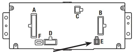
- Connect the 16-pin harness with stripped leads into port “B” in the touchscreen display.
- Connect the 6537 harnesses to the wiring harnesses in the vehicle. Then insert the 6537 harnesses into port “A” in the touchscreen display. But do not install this harness until exactly before step 1 from the Programming section. This is a timed process
- Connect the 4-pin harness with yellow RCA jacks into port “C” in the touchscreen display.
- Connect the hazard harness into port “D” in the touchscreen display, and then to the wiring harness in the vehicle. Ensure that this is the 8-pin connector from the climate control. The touchscreen also uses the same connector. Using the wrong connector will cause a jam with the vehicle’s CANBUS.
- Disregard port “E”, it will not be used in this application.
- Port “F” is an updated port for future firmware upgrades.
- Locate the factory antenna connector in the dash and complete all necessary connections to the radio.Use the antenna adapter provided to adapt the factory antenna connector to the aftermarket radio.
Note: DO NOT CONNECT!
PROGRAMMING
- Refer to step 2 from the Installation section.
- Press the push-to-start button to start the vehicle.
- Program the kit:a. Once the touchscreen display loads up, select the vehicle type.b. Wait until the radio comes on, and the touchscreen display shows SWC Configured.This process may take up to 3 minutes.Note: If the touchscreen display does not load up, or the radio doesn’t come on within 3 minutes, and/or the touchscreen display does not show SWC Configured, check all connections, then reset the interface and try again. Refer to the Troubleshooting section.
- Cycle the key off. If the driver’s door is closed, open and close the door. Cycle the key back on.
- Test all functions of the installation for proper operation, before reassembling the dash.Note: The clock and compass in the driver’s information center will no longer be functional.
FINAL ASSEMBLY
- Secure the completed assembly into the upper dash using the factory hardware.
- Snap the radio trim panel with touchscreen display over the completed assembly, and then reassemble the dash in reverse order of disassembly.
TOUCHSCREEN DISPLAY OPERATION
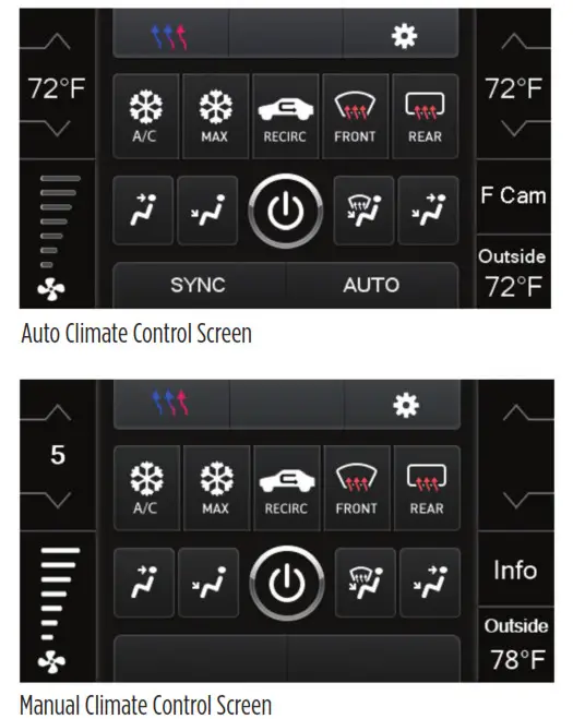
Climate Control screen
- This is the climate control screen that will be displayed on the touchscreen display. This is considered the Main Menu.
- The upper left tab with (3) arrows will take you to the screen where the Heated/Cooled Seats, Heated Steering, and Mirror Dimming are now placed, if applicable.
- The upper right tab with a gear icon will take you to the Settings screen.
- The climate controls will function in the same manner that they did with the factory climate controls.
- For models with rear climate controls, the button labeled REAR will take you to the rear climate control menu.
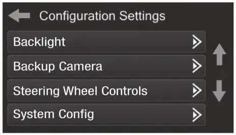
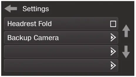
Configuration Settings
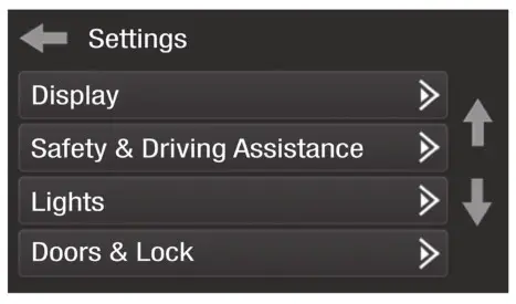
- Display
- Backlight – For controlling the color of the buttons and back-light intensity.• Language• Units
- Safety & Driving Assistance – Factory features
- Lights – Factory features
- Doors & Locks – Factory features
- Engine Off Options – Factory features
- Steering Wheel Controls• Remap Buttons – For remapping the steering wheel control buttons• Dual Assign – For dual assigning the steering wheel control buttons (long button press)
- Select Radio – For auto-detecting the radio, or changing the radio type
- Digital Amp Gain – For adjusting the output gain to the amplifier.
- System Configuration• About – Information regarding the software in the kit• Reset Vehicle Type – To reset the kit to default settings• Comfort Options Override – Provides the ability to disable/enable certain factory options
- Headrest Fold – On/Off
- Backup Camera• Enable/disable the backup camera image to the touchscreen display. Disabled by default.
STEERING WHEEL CONTROL SETTINGS
Remap buttons
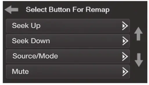
- The interface has the ability to change the button assignment for the steering wheel control audio buttons, except Volume-Up and Volume-Down. Follow the prompts on the touchscreen display to remap the steering wheel control audio button(s) to your liking.Note: The aftermarket radio may not have all of these commands. Please refer to the manual provided with the radio, or contact the radio manufacturer, for specific commands recognized by that particular radio.
Dual Assign
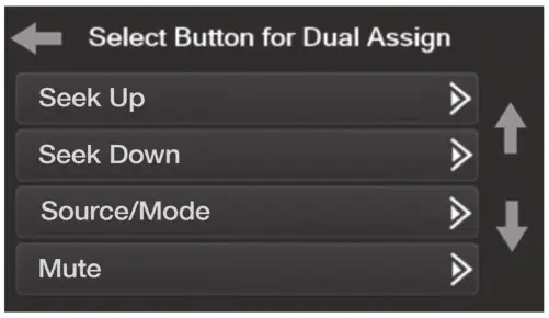
- The interface has the capability to assign two functions to a single button, except VolumeUp and Volume-Down. Follow the prompts on the touchscreen display to program the button(s) to your liking.Note: Seek-Up and Seek-Down come programmed as Preset-Up and Preset-Down for a long button press.
Select Radio
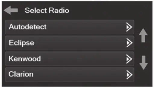
- To show which brand radio is “auto-detected” to the interface, press the “Autodetect” button. The radio detected will have a filled-in circle. If the incorrect radio is shown, select the proper radio.
- Following is a list of radio manufacturers that the interface presently acknowledges. Others may be added at a later date. Universal “2 or 3 wire” radios can show up as any of these radio manufacturers.
| Eclipse (Type 1) †Kenwood ‡Clarion (Type 1) †Sony / Dual | JVCPioneer/JensenAlpine *VisteonValor | Clarion (Type 2) †Metra OEEclipse (Type 2) †LG | Parrot **SITEPhilipsJBL |
* Note: If the interface shows an Alpine radio, and you do not have an Alpine radio, that means the interface does not detect a radio connected it, i.e., an open connection. Verify that the 3.5mm jack is connected to the correct steering wheel jack/wire in the radio.** Note: The AX-SWC-PARROT is required (sold separately). Also, the Parrot radio must be updated to rev. 2.1.4 or higher through www.parrot.com.† Note: If you have a Clarion radio and the steering wheel controls do not work, change the radio type to the other Clarion radio type; same for Eclipse.‡ Note: If you have a Kenwood radio and the touchscreen display shows a JVC radio, change the radio type to Kenwood.
TROUBLESHOOTING
Resetting the interfaceOption # 1
- With everything connected and the car running.
- Hold the bottom (2) buttons for 3 seconds, then release. (Figure A)(The screen will turn black and then put you in the vehicle selection screen)
- Select your vehicle and wait till the “SWC Configured “ appears on the screen.
- Turn ignition off and start the vehicle, then test your interface.
Option #2
- With the vehicle running, press the Reset Vehicle Type button mentioned in System Configuration.
- Refer to Programming, step 3, from this point.
![]() 99-6537BINSTALLATION INSTRUCTIONS
99-6537BINSTALLATION INSTRUCTIONS

If you are having difficulties with the installation of this product, contact our Tech Support line either by phone at 1-800-253-TECH, or email at [email protected]. Before doing so, look over the instruction booklet a second time and ensure that the installation was performed exactly as the instruction booklet is stated. Have the vehicle apart and ready to perform troubleshooting steps before contacting Metra/Axxess Tech Support.
 ® KNOWLEDGE IS POWEREnhance your installation and fabrication skills by enrolling in the most recognized and respected mobile electronics school in our industry. Log onto www.installerinstitute.com or call 800-354-6782 for more information and take steps toward a better tomorrow.
 Metra recommends MECP certified technicians
 report this ad
Metra. The World’s Best Kits®.MetraOnline.com© COPYRIGHT 2020 METRA ELECTRONICS CORPORATIONREV. 10/19/20 INST99-6537B
References
[xyz-ips snippet=”download-snippet”]