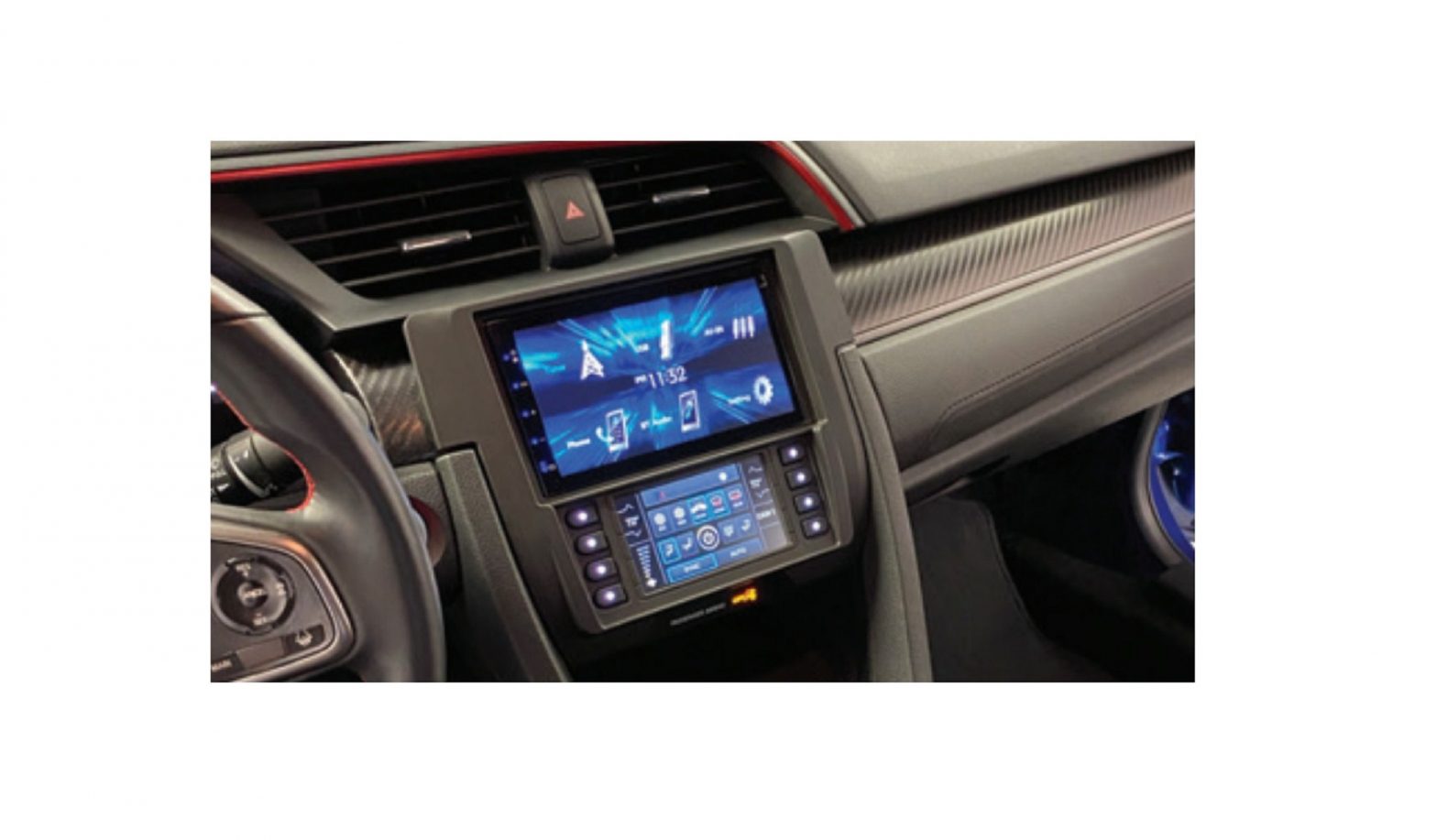
MeTra 99-7821B Honda Civic Installation Guide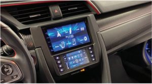

Honda Civic (Excluding LX models) 2016-2021Visit MetraOnline.com for more detailed information about the product and up-to-date vehicle specific applications. Note: Additional parts required to retain factory amplifier
KIT FEATURES
- ISO DIN radio provision with pocket
- ISO DDIN radio provision
- Painted matte black
- Touchscreen display for climate and personalization features
- Retains the factory backup camera and LaneWatch camera
- Retains audio controls on the steering wheel
- Provides NAV outputs (parking brake, reverse, speed sense)
- Additional purchase of AXSP-HN is required to retain factory amplifier. Identifiable when equipped with factory sub-woofer or center channel speakers.
WIRING & ANTENNA CONNECTIONS
- Wiring Harness: Included in kit
- Antenna Adapter: Included in kit
TOOLS REQUIRED
- Panel removal tool
- Phillips screwdriver
Attention! Let the vehicle sit with the key out of the ignition for a few minutes before removing the factory radio. When testing the aftermarket equipment, ensure that all factory equipment is connected before cycling the key to ignition.
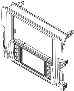
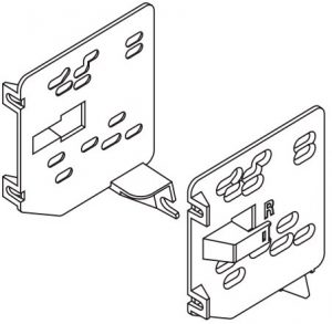
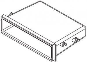
KIT COMPONENTS
- Radio trim panel

- Radio brackets
- Pocket
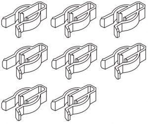
- (4) #8 x 3/8” Phillips screws
- (8) Plastic panel clips
- Axxess wiring harness and interface (not shown)
- Antenna adapter (not shown)

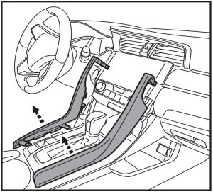
DASH DISASSEMBLY
- Unsnap and remove the side trim panels from the center console. (Figure A)
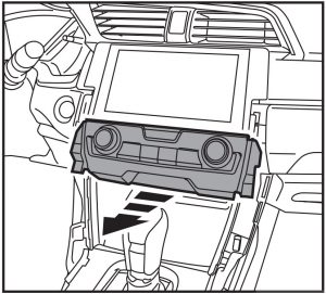
- Unsnap and remove the climate control panel. (Figure B)
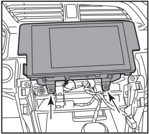
- Remove (2) Philips screws securing the radio and then remove. (Figure C)
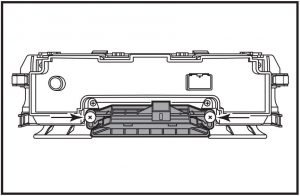
- Remove the (2) screws securing the factory passenger airbag indicator and remove it from the factory climate controls. (Figure D)
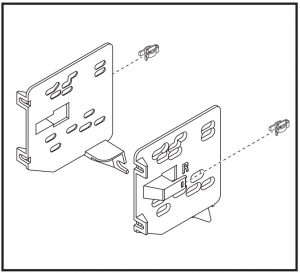
KIT PREPARATION
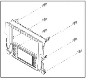
- Attach the supplied (6) plastic clips to the radio trim panel. (Figure A)
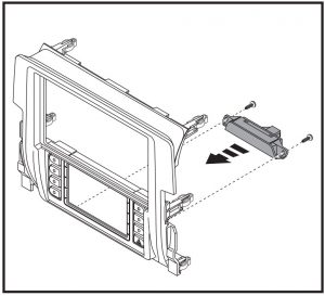
- Attach the airbag indicator to the radio trim panel using the factory screws.(Figure B)
- Attach the supplied (2) plastic clips to the radio brackets. (Figure C)
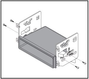
KIT ASSEMBLY
ISO DIN radio provision with pocket
- Attach the pocket to the radio brackets using the (4) Phillips screws provided. (Figure A)
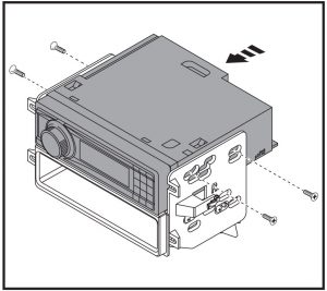
- Slide the radio into the assembly, and then secure it using the screws supplied with the radio. (Figure B)
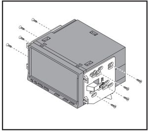
ISO DDIN radio provision
- Attach the radio brackets to the radio using the hardware provided with the radio. (Figure A)
AXXESS INTERFACE INSTALLATION
INTERFACE FEATURES
- Provides accessory power (12-volt 10-amp)
- Provides 12-volt illumination output
- Retains R.A.P. (retained accessory power)
- Touchscreen display for climate and personalization features
- Retains the factory backup camera
- Retains the LaneWatch camer
- Retains audio controls on the steering wheel
- Provides NAV outputs (parking brake, reverse, speed sense)
- Retains balance and fade
- Micro-B USB updatable
- Can be used in non-amplified, or amplified models*
Additional purchase of AXSP-HN is required to retain amplifier.
INTERFACE COMPONENTS
- Touchscreen harness (LD-HONTOUCH)
- USB retentions harness (AXUSB-TY4)
- Camera retention interface 40-HD12 & 44-EC144 (antenna adapter)
- Female 3.5mm jack
TOOLS REQUIRED
- Crimping tool and connectors, or solder gun, solder, and heat shrink
- Tape
- Wire cutter
- Zip ties
CONNECTIONS
For models without a factory amp
From the LD-HONTOUCH harness (loose wires for aftermarket radio)
- Connect the Black wire to the ground wire.
- Connect the Yellow wire to the battery wire.
- Connect the Red wire to the accessory wire.
- Connect the Orange/White wire to the illumination wire.
- Connect the Blue/Pink wire to the VSS/speed sense wire
- Connect the Light Green wire to the parking brake wire.
For the following (8) connections, cut off the RCA jacks to expose the speaker wire inside.
- Connect the White wire to the left front positive speaker output.
- Connect the White/Black wire to the left front negative speaker output.
- Connect the Gray wire to the right front positive speaker output.
- Connect the Gray/Black wire to the right front negative speaker output.
- Connect the Green wire to the left rear positive speaker output.
- Connect the Green/Black wire to the left rear negative speaker output.
- Connect the Purple wire to the right rear positive speaker output.
- Connect the Purple/Black wire to the right rear negative speaker output.
For models with a factory amp (will require the AXSP-HN) (sold separately)
From the LD-HONTOUCH harness (loose wires for the aftermarket radio)
- Connect the Black wire to the ground wire.
- Connect the Yellow wire to the battery wire.
- Connect the Red wire to the accessory wire.
- Connect the Blue/White wire to the amp turn-on wire.
- Connect the Orange/White wire to the illumination wire.
- Connect the Blue/Pink wire to the VSS/speed sense wire
- Connect the Light Green wire to the parking brake wire.
- Connect the White RCA to the Left Front Pre-out.
- Connect the Gray RCA to the Right Front Pre-out.
The following wires will not be used in this application.Green/Purple and Blue/Pink (labeled TBA), Green and Purple RCAS
Connections from the 16 pin harness with Yellow RCA
- Connect the Yellow RCA Jack to the backup camera input.
- Connect the Green/Purple wire to the reverse wire
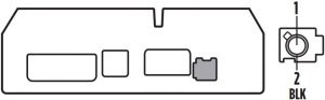
3.5mm jack steering wheel control retention:
The 3.5mm jack is to be used to retain audio controls on the steering wheel control.
- For the radios listed below: Connect the included female 3.5mm connector with stripped leads, to the male 3.5mm SWC jack from the car side harness. Any remaining wires tape off and disregard:
- Eclipse: Connect the steering wheel control wire, normally Brown, to the Brown/White wire of the connector. Then connect the remaining steering wheel control wire, normally Brown/White, to the Brown wire of the connector.
- Metra OE: Connect the steering wheel control Key 1 wire (Gray) to the Brown wire.
- Kenwood or select JVC with a steering wheel control wire: Connect the Blue/Yellow wire to the Brown wire.Note: If your Kenwood radio auto detects as a JVC, manually set the radio type to Kenwood. See the instructions under changing radio type.
- XITE: Connect the steering wheel control SWC-2 wire from the radio to the Brown wire.
- Parrot Asteroid Smart or Tablet: Connect the 3.5mm jack into the AX-SWC-PARROT (sold separately), and then connect the 4 pin connector from the AX-SWC PARROT into the radio.Note: The radio must be updated to rev. 2.1.4 or higher software.
- Universal “2 or 3 wire” radio: Connect the steering wheel control wire, referred to as Key-A or SWC-1, to the Brown wire of the connector. Then connect the remaining steering wheel control wire, referred to as Key-B or SWC-2, to the Brown/White wire of the connector. If the radio comes with a third wire for ground, disregard this wire.Note: After the interface has been programmed to the vehicle, refer to the manual provided with the radio for assigning the SWC buttons. Contact the radio manufacturer for more information.
- For all other radios: Connect the 3.5mm jack into the port on the radio designated for an external steering wheel control interface. Refer to the manual provided with the radio if in doubt as to where the 3.5mm jack goes to.
ANTENNA CONNECTIONS
The antenna connection is only available at the factory tuner behind the passenger rear side trim panel. (Figure A)
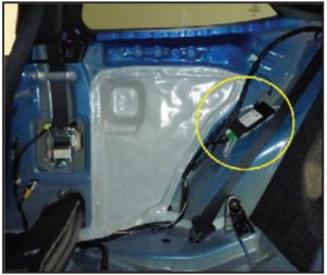
Connection
Route the antenna extension from the radio location to the tuner location. Plug in the antenna cable and connect the Blue wire to your radio’s Amp turn on output.
Disconnect the cable from the factory tuner and connect the antenna extension cable. Proper access to the tuner will require rear seat and side trim panel removal.
AXSP-HN connections. Sold separately for retaining the factory amplifier.
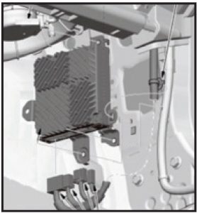
The Amplifier is located behind the front passenger kick panel. To retain the factory amplifier, route and connect the 48” SPDIF connector coming from the LD-HONTOUCH harness into the factory amplifier.
Removal Steps
- Unclip and remove the panel under the glove box. (Figure A)
- Open the glove box, squeeze both sides inward, and pull up and back to remove.
- Unclip the Front Passenger Kick Panel
- Disconnect the Amplifier’s main input cable. (Figure B)
- Route and connect the 48” SPDIF connector coming from the LD HONTOUCH harness into the factory amplifier
- Stereo Amplifier Connector
INSTALLATION AND PROGRAMMING
It is highly advisable to read the following steps beforehand, to ensure a clear understanding of what is to be expected.
With the vehicle completely off:
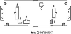
From the LD-HONTOUCH
- Connect the 16-pin harness into port “B” in the touchscreen display
- Connect the 22-pin connector that has the “Touchscreen Label on it” into port “A” of the Touchscreen Display.
- Connect the 10-pin connector into port “D” and then to the Factory 12 pin connector that was removed from the factory climate control panel.
- Locate the camera interface and connect the 16 pin with Yellow RCA and 22-pin plug from the LD-HONTOUCH.
- Connect the Yellow RCA to the radios backup camera input
- Disregard Port “E” & “C”
- Port “F” is used for firmware updates
- If the vehicle is factory amplified, connect the AXSP-HN to the 14-pin harness of the LD-HONTOUCH. If not amplified disregard.
- Connect the LD-HONTOUCH wiring harness to vehicle. These connectors were removed from the factory radio
- Be sure to plug in the new radio’s harness before programming.
- With all connections made, now you “Press the push-to-start button to start the vehicle.
Programing the kit
- Once the touchscreen display powers on, select 2016-2020 Civic.
- Wait until the aftermarket radio powers on, and the touchscreen display shows SWC Configured. This process could take about 3 mins.
- Cycle the key off. If the driver’s door is closed, open and close the door. Start the vehicle
- Test all functions of the installation for proper operation, before reassembling the dash.
Note: If the radio or touchscreen do not power on within 3 minutes, reset the interface and try again. Refer to the Troubleshooting section for details.
TOUCHSCREEN DISPLAY OPERATION
Climate Control screen
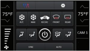
- This is the climate control screen, which will be displayed on the touchscreen display. This is also considered the main menu. The climate controls will function in the same manner that they did with the factory climate controls.
- The upper left tab with (3) arrows will access the Heated/Cooled seats, if equipped.
- Factory camera modes are available and view modes can be changed while in reverse. (Wide View Mode, Normal View Mode, Top Down View Mode) Press the CAM1 icon to change the viewing angle of the backup camera while in reverse.
- The upper right tab with a gear icon will access the Configuration Settings screen.
Climate Control screen
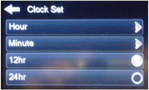
Setting the Clock (will display the time on the instrument cluster)
- Under Configuration Settings
- Clock Settings
- Clock set:
- Hour: Changes the Hour
- Minutes: Change the Minutes
- 12hr: displayed in 12hr time
- 24hr: displays as Military time
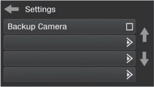
Configuration Settings
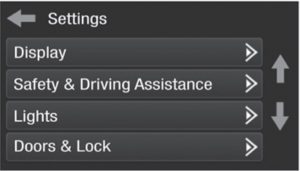
- Display
- Backlight – For controlling the color of the buttons and back-light intensity.
- Language
- Units
- Safety & Driving Assistance – Factory features
- Lights – Factory features
- Doors & Locks – Factory features
- Engine Off Options – Factory features
- Steering Wheel Controls
- Remap Buttons – For remapping the steering wheel control buttons
- Dual Assign – For dual assigning the steering wheel control buttons (long button press)
- Select Radio – For auto detecting the radio, or changing the radio type
- Digital Amp Gain – For adjusting the output gain to the amplifier
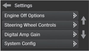
- System Configuration
- About – Information regarding the software in the kit
- Reset Vehicle Type – To reset the kit to default settings
- Comfort Options Override – Provides the ability to disable/enable certain factory options
- Backup Camera
- Enable/disables the backup camera image to the touchscreen display. Disabled by default.
- Enable/disables the backup camera image to the touchscreen display. Disabled by default.
STEERING WHEEL CONTROL SETTINGS
Remap Buttons
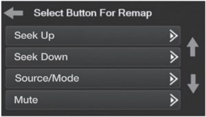
- The interface has the ability to change the button assignment for the steering wheel control audio buttons, except Volume-Up and Volume-Down. Follow the prompts on the touchscreen display to remap the steering wheel control audio button(s) to your liking.Note: The aftermarket radio may not have all of these commands. Please refer to the manual provided with the radio, or contact the radio manufacturer, for specific commands recognized by that particular radio.
Dual Assign
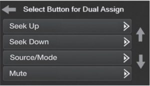
- The interface has the capability to assign two functions to a single button, except Volume-Up and Volume-Down. Follow the prompts on the touchscreen display to program the button(s) to your liking.Note: Seek-Up and Seek-Down come programmed as Preset-Up and Preset-Down for a long button press.
Select Radio
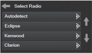
- To show which brand radio is “auto detected” to the interface, press the “Autodetect” button. The radio detected will have a filled in circle. If the incorrect radio is shown, select the proper radio.
- Following is a list of radio manufacturers that the interface presently acknowledges.Others may be added at a later date. Universal “2 or 3 wire” radios can show up as any of these radio manufacturers.
| Eclipse (Type 1) † | JVC | Clarion (Type 2) † | Parrot ** |
| Kenwood ‡ | Pioneer/Jensen | Metra OE | XITE |
| Clarion (Type 1) † | Alpine * | Eclipse (Type 2) † | Philips |
| Sony / Dual | Visteon | LG | JBL |
|
– |
Valor |
– |
– |
- Note: If the interface shows an Alpine radio, and you do not have an Alpine radio, that means the interface does not detect a radio connected it, i.e., an open connection. Verify that the 3.5mm jack is connected to the correct steering wheel jack/wire in the radio.
- Note: The AX-SWC-PARROT is required (sold separately). Also, the Parrot radio must be updated to rev. 2.1.4 or higher through www.parrot.com.
- † Note: If you have a Clarion radio and the steering wheel controls do not work, change the radio type to the other Clarion radio type; same for Eclipse.
- ‡ Note: If you have a Kenwood radio and the touchscreen display shows a JVC radio, change the radio type to Kenwood
TROUBLESHOOTING
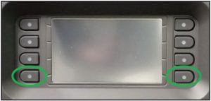
Resetting the interface
Option # 1
- With everything connected and the car running.
- Hold the bottom (2) buttons for 3 seconds, then release. (Figure A) (The screen will turn black and then put you in the vehicle selection screen)
- Select your vehicle and wait till the “SWC Configured “ appears on the screen.
- Turn ignition off and start vehicle, then test your interface.
Option #2
- With the vehicle running, press the Reset Vehicle Type button mentioned in System Configuration.
- Refer to Programming, step 3, from this point.
FINAL ASSEMBLY
- Secure the radio into the dash and reassemble the dash in reverse order of disassembly using the new radio trim panel.
Customer Service
Having difficulties? We’re here to help.
![]() Contact our Tech Support line at: 386-257-1187
Contact our Tech Support line at: 386-257-1187![]() Or via email at: [email protected]
Or via email at: [email protected]
Tech Support Hours (Eastern Standard Time)
- Monday – Friday: 9:00 AM – 7:00 PM
- Saturday: 10:00 AM – 7:00 PM
- Sunday: 10:00 AM – 4:00 PM
KNOWLEDGE IS POWEREnhance your installation and fabrication skills by enrolling in the most recognized and respected mobile electronics school in our industry.Log onto www.installerinstitute.com or call 800-354-6782 for more information and take steps toward a better tomorrow.®
Metra recommends MECP certified technicians
Please Scan QR Code For More Detail:
References
[xyz-ips snippet=”download-snippet”]