Metra Ford / Mazda Multi-Kit Instructions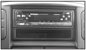
KIT FEATURES
- DIN radio provision with pocket
- ISO DIN radio provision with pocket
KIT COMPONENTS
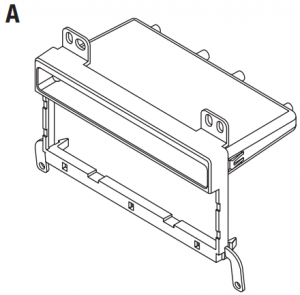
- A) Radio housing

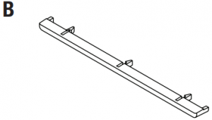
- B) Radio housing trim piece “A”
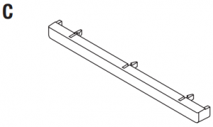
- C) Radio housing trim piece “B”
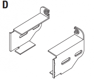
- D) ISO Brackets
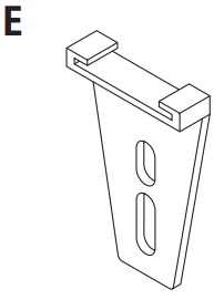
- E) Rear support
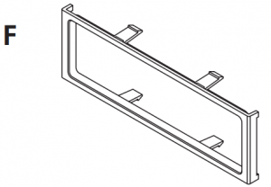
- F) ISO Trim plate
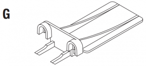
- G) Mounting bracket
- H) (4) #8 x 3/8” Phillips screws

APPLICATIONS See application list inside cover
WIRING & ANTENNA CONNECTIONS (sold separately)
Wiring Harness:
- Please visit www.metraonline.com for specific interface applicationsAntenna Adapter:
- Not required
TOOLS REQUIRED
- Panel removal tool
- Phillips screwdriver
- 86-5618 Ford radio removal keys
CAUTION! All accessories, switches, climate controls panels, and especially air bag indicator lights must be connected before cycling the ignition. Also, do not remove the factory radio with the key in the on position, or while the vehicle is running.
Dash Disassembly
Ford Crown Victoria 1995-2011/Econoline 1997-2008/Explorer 1995 2001/Explorer Sport Trac 2001-2005/F-250/350/450/550 1999 2004/F-650/750 2000-2010/Ranger 1995-2011,Lincoln Continental 1995-1997/Mark 8 1996-1998/Town Car 1995 2002, Mazda B-Series Pickup 1995-2009,Mercury Grand Marquis 1995-2010/Marauder 2003-2004/Mariner 2005-2007/Mountaineer 1997-2001.
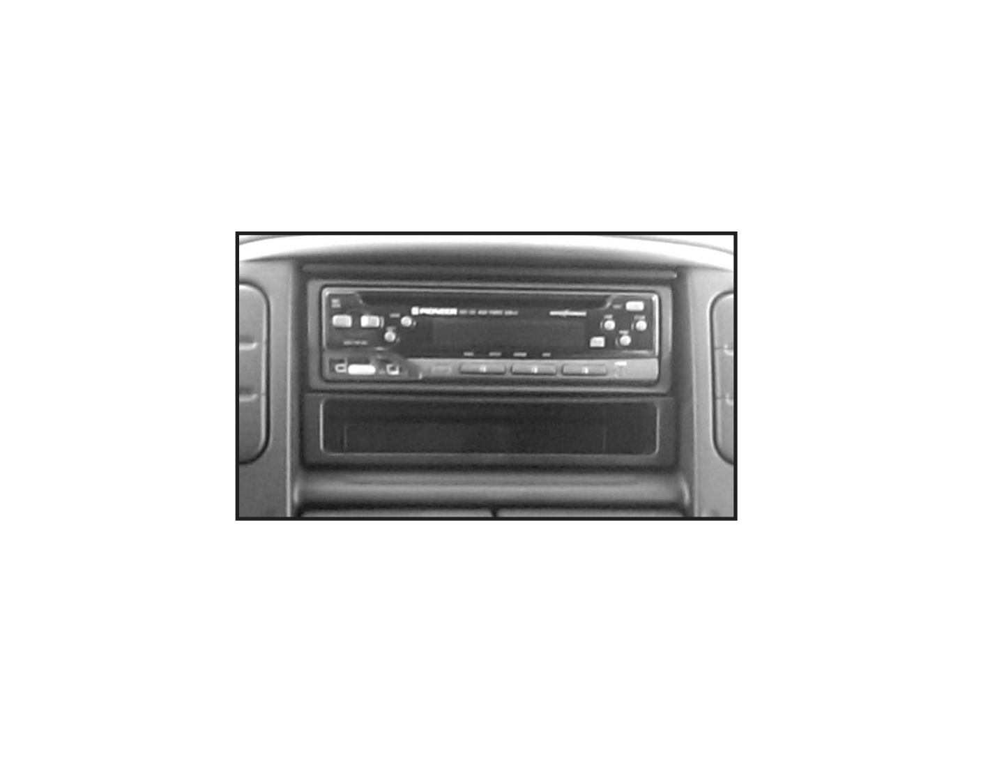
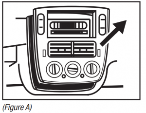
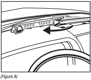
- Using Metra’s 86-5618, pull the factory radio from the dash and disconnect the wiring. (Figure A)
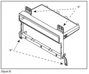
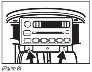
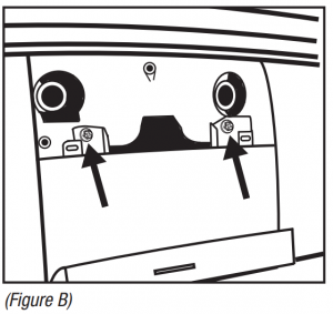
- Cut and remove the top mounting legs “A” and the bottom mounting legs “B” from the radio housing. (Figure B)Continue to kit preparation

 Continue to kit preparation
Ford Expedition 1997-2002/F-150 1997-2003/ F-150 (Heritage) 2004/F-250 1998 Excursion 2000-2005, Lincoln Blackwood 2002/Navigator 1997-2002.
- Place your index fingers on the inner edges of the A/C vents and push inward. Grasp the exposed lip of each vent opening and pull out on the radio trim bezel. Remove the dash trim bezel (airbag wiring does not need to be disconnected). (Figure A)
- Using Metra’s 86-5618, pull the factory radio from the dash and disconnect the wiring.
- Remove the (2) uppermost mounting screws from the climate control panel.
- Cut and remove the top mounting legs “A” from the radio housing. (Figure B)Note: For the Ford Expedition 1997-1998, F-150 1997-1998, F-250 1998 remove the rear support bracket from the dash cavity.Continue to kit preparation

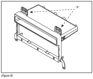 Note: For the Ford Expedition 1997-1998, F-150 1997-1998, F-250 1998 remove the rear support bracket from the dash cavity.Continue to kit preparation
Ford Expedition (without NAV) 2003-2006
- Remove (2) 9/32” screws from above instrument cluster. (Figure A)
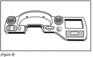
- Unclip and remove entire panel surrounding radio, climate controls, and instrument cluster. (Figure B)
- Remove (2) 9/32” screws securing radio.Continue to kit preparation

Ford Explorer 2002-2005 Mercury Mountaineer 2002-2005
- Unclip and remove entire panel surrounding radio including climate controls and vents. (Figure A)
- Remove (2) 9/32” screws securing radio. (Figure B)Continue to kit preparation
 Continue to kit preparation
Ford Mustang 2001-2004
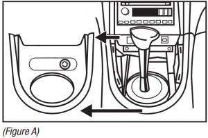
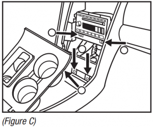
- Unclip and remove shift lever trim panel. (Figure A)
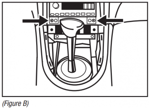
- Unclip and remove the entire panel surrounding the radio and climate controls including the vents. (Figure B)
- Remove (2) 9/32” screws securing radio. (Figure B)Continue to kit preparation
 Continue to kit preparation
Lincoln Aviator 2003-2005
- Unclip and remove vent panel above radio on top of dashboard. (Figure A)
- Remove (2) 9/32” screws exposed under panel removed in step 1. (Figure B)
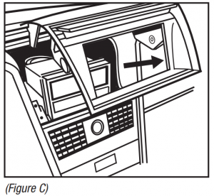
- Unclip and remove panel around radio with door in it. (Figure C)Continued on the next pageLincoln Aviator 2003-2005 (Cont)
- Unclip and remove vents below radio. (Figure D)
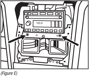
- Remove (2) 9/32” screws securing radio. (Figure E)Continue to kit preparation
 Continued on the next pageLincoln Aviator 2003-2005 (Cont)
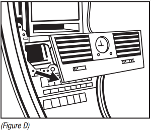
 Continue to kit preparation
Lincoln Navigator (with NAV, THX amp) 2003-2006 Navigator (without NAV) 2003-2006
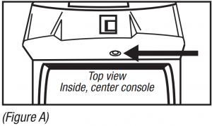
- Open center console and remove (1) push pin from back of power window switch panel. (Figure A)
- Unclip and remove panel.
- Remove (2) 9/32” screws exposed on shifter panel then unclip and move shifter panel off to side. (Figure B, C)
- Remove (2) 9/32” screws exposed under ashtray assembly. (Figure C)
- Unclip and remove entire panel surrounding climate controls and radio.
- Remove (2) 9/32” screws securing radio. (Figure C)Continue to kit preparation

 Continue to kit preparation
Kit Preparation
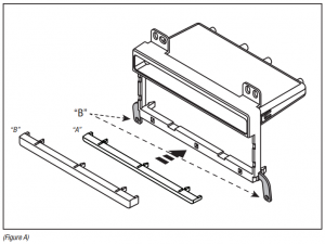
- Attach the corresponding radio housing trim piece to theradio housing. (Figure A)The following applications will use radio housing trim piece “B” (thicker trim piece):Ford Expedition (without NAV) 2003-2006Ford Explorer 2002-2005Ford Mustang 2001-2004Lincoln Aviator 2003-2005Lincoln Navigator (without NAV) 2003-2006Lincoln Navigator (with NAV, with THX amp) 2003-2006Mercury Mountaineer 2002-2005
- Cut and remove the mounting legs (B) from the radio housing. (Figure A)Note: The kit is illustrated upside down of how it will actually mount into the vehicle. Continue to kit assembly.All other applications will use radio housing trim piece “A” (thinner trim piece): Continue to kit assembly.
 Note: The kit is illustrated upside down of how it will actually mount into the vehicle. Continue to kit assembly.All other applications will use radio housing trim piece “A” (thinner trim piece): Continue to kit assembly.
DIN radio provision with pocket
- Remove the metal DIN sleeve from the aftermarket radio.
- Slide the sleeve into the radio housing and secure by bending the metal locking tabs down.
- Slide the radio into the sleeve until it clicks in.
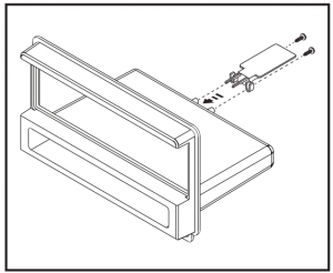
- Secure the mounting bracket to the back of the radio housing with the (2) #8 x 3/8” Phillips screws supplied. (Figure A)(Figure A)
- Slide the rear support onto the mounting bracket, and then mount the support to the back of the radio using the hardware included with the radio. (Figure B)(Figure B)Note: For the Ford Expedition and Lincoln Navigator, cut the support as shown in Figure C. (Figure C)(Figure C)
- Locate the factory wiring harness and antenna connector in the dash. Metra recommends using the proper mating adapter from Metra or AXXESS. Test the radio for proper operation.
- Reassemble the dash in reverse order of disassembly.
 (Figure A)
 (Figure B)Note: For the Ford Expedition and Lincoln Navigator, cut the support as shown in Figure C. (Figure C)
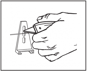 (Figure C)
ISO DIN radio provision with pocket
- Attach the ISO brackets to the radio housing, and then secure using the (2) #8 x 3/8” Phillips screws provided and then snap the correct radio housing trim piece to the radio housing. (Figure A)(Figure A)
- Remove the metal DIN sleeve and trim ring from the aftermarket radio.
- Slide the radio into the rear of the radio opening and then secure with the screws supplied with the radio. (Figure B)(Figure B)
- Snap the trim plate into the radio housing. (Figure B)
- Locate the factory wiring harness and antenna connector in the dash. Metra recommends using the proper mating adapter from Metra or AXXESS. Test the radio for proper operation.
- Reassemble the dash in reverse order of disassembly.
 (Figure A)
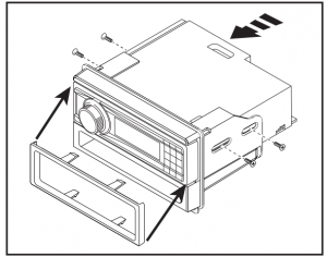 (Figure B)
DIN radio provision with pocket
- Remove the metal DIN sleeve from the aftermarket radio.
- Slide the sleeve into the radio housing and secure by bending the metal locking tabs down.
- Slide the radio into the sleeve until it clicks in.
- Secure the mounting bracket to the back of the radio housing with the (2) #8 x 3/8” Phillips screws supplied. (Figure A)(Figure A)
- Slide the rear support onto the mounting bracket, and then mount the support to the back of the radio using the hardware included with the radio. (Figure A)
- Locate the factory wiring harness and antenna connector in the dash. Metra recommends using the proper mating adapter from Metra or AXXESS. Test the radio for proper operation.
- Reassemble the dash in reverse order of disassembly
 (Figure A)
ISO DIN radio provision with pocket
- Attach the ISO brackets to the radio housing, and then secure using the (2) #8 x 3/8” Phillips screws provided. (Figure A)(Figure A)
- Remove the metal DIN sleeve and trim ring from the aftermarket radio.
- Slide the radio into the rear of the radio opening and then secure with the screws supplied with the radio. (Figure B)(Figure B)
- Snap the trim plate into the radio housing. (Figure B)
- Locate the factory wiring harness and antenna connector in the dash. Metra recommends using the proper mating adapter from Metra or AXXESS. Test the radio for proper operation.
- Reassemble the dash in reverse order of disassembly.
 (Figure A)
 (Figure B)
IMPORTANTIf you are having difficulties with the installation of this product, please call our Tech Support line at 1-386-257-1186. Before doing so, look over the instructions a second time, and make sure the installation was performed exactly as the instructions are stated. Please have the vehicle apart and ready to perform troubleshooting steps before calling.
 KNOWLEDGE IS POWEREnhance your installation and fabrication skills by enrolling in the most recognized and respected mobile electronics school in our industry . Log onto www.installerinstitute.edu or call 1-386-672-5771 for more information and take steps toward a better tomorrow.
 Metra recommends MECP certified technicians
References
[xyz-ips snippet=”download-snippet”]