![]()
99-7804NSTALLATION INSTRUCTIONS

Honda Accord 2013-2017
KIT FEATURES
- ISO DIN radio provision with pocket
- ISO DDIN radio provision
- Painted two-tone to match the factory dash99-7804B – Black with Silver accent99-7804HG – Black with High Gloss accent
- Retains factory color screen
KIT COMPONENTS
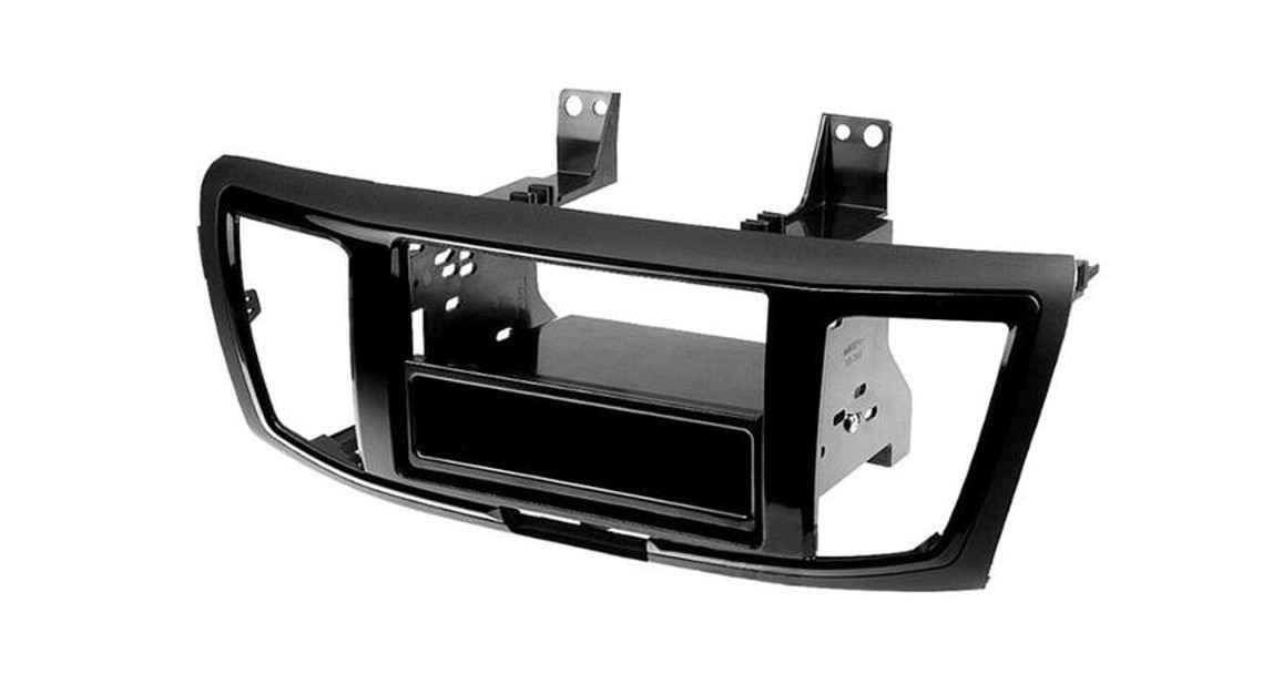
- A) Radio housing trim panel
- B) Radio brackets
- C) Top bracket
- D) Pocket
- E) (6) White panel clips
- F) (8) #6 x 3/8” Phillips screws
- G) (8) #8 x 3/8” Phillips screws
- H) Display retention interface and harness (not shown)

WIRING & ANTENNA CONNECTIONSWiring Harness: IncludedAntenna Adapter: 40-HD11 (sold separately)Steering wheel control interface: ASWC-1/AXSWC (sold separately)
TOOLS REQUIRED
- Panel removal tool
- Phillips screwdriver
CAUTION! All accessories, switches, climate controls panels, and especially airbag indicator lights must be connected before cycling the ignition. Also, do not remove the factory radio with the key in the on position, or while the vehicle is running.
DASH DISASSEMBLY
- Unclip and remove the side trim panels from each side of the console. (Figure A)

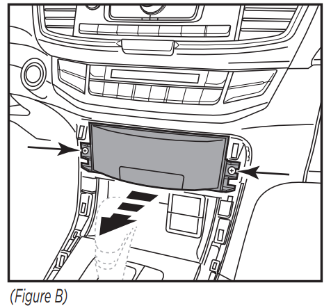
- Remove (2) Phillips screws exposed on pocket then remove the pocket. (Figure B)
- Remove (2) 8mm screws facing up on the bottom of the radio chassis inside the pocket cavity. (Figure C)
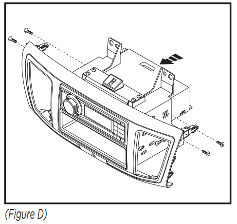
- Unclip and remove the small trim panel between the radio and steering column.Note: Models with auto climate will have a thermistor hose attached to this panel.Disconnect the hose under the dash above the gas pedal to give it enough slack before re-installing the panel. (Figure D)Continue on the next page
DASH DISASSEMBLY (CONT)
- Remove (2) Phillips screws on top of the radio. (Figure E)
- Unclip and remove the radio assembly. (Figure F)|
- Remove (1) Phillips screw from each A/C vent then unclip and remove the vents. (Figure G)
- Remove (2) Phillips screws securing the hazard light switch and retain for kit assembly.Continue to Kit Preparation


KIT PREPARATION
- Attach the hazard light switch to the radio trim panel using (2) of the supplied #8 x 3/8” Phillips screws. (Figure A)
- Attach the (6) white panel clips to the radio housing trim panel. (Figure A)Continue to Kit Assembly

KIT ASSEMBLY
ISO DIN radio provision with pocket
- Attach the radio brackets to the radio housing trim panel using (4) of the #6 x 3/8” Phillips screws. (Figure A)
- Attach the top bracket to the top of the radio brackets using (4) of the #6 x 3/8” Phillips screws supplied. (Figure B)
- Mount the pocket to the bracket/panel assembly with (4) of the #8 x 3/8” Phillips screws supplied. (Figure C)
- Slide the radio into the assembly and secure with screws supplied with the radio. (Figure D)
- Attach the A/C vents to the radio trim panel and secure using (2) of the supplied #8 x 3/8” Phillips screws. (Figure E)
- Locate the factory wiring harness in the dash. Follow the Wiring and Initialization section of this manual before completing the installation.
- Mount the new radio assembly into the dash and reassemble dash in reverse order of disassembly.


ISO DDIN radio provision
- Attach the radio brackets to the radio housing trim panel using (4) of the #6 x 3/8” Phillips screws. (Figure A)
- Attach the top bracket to the top of the radio brackets using (4) of the #6 x 3/8” Phillips screws supplied. (Figure B)
- Slide the radio into the bracket/trim panel assembly and secure to the assembly using the screws supplied with the radio. (Figure C)
- Attach the A/C vents to the radio trim panel and secure using (2) of the supplied #8 x 3/8” Phillips screws. (Figure D)
- Locate the factory wiring harness in the dash. Follow the Wiring and Initialization section of this manual before completing the installation.
- Reassemble the dash in reverse order of disassembly.


WIRING INSTRUCTIONS
Harnesses Included:
- 24-pin gray Honda connector to 14-pin black interface connector, with pre-wired 12-pin black ASWC-1/AXSWC harness.
- 24-pin and 12-pin gray Honda connector to 22-pin black interface connector, with a Yellow female RCA.
- 8-pin gray Honda subwoofer connector to White RCA.
- Blue connector to White connector LVDS cable.
If the vehicle has Bluetooth buttons and you wish to retain them (Non-touch screen models):
- Connect the Gray/Blue wire from the ASWC-1/AXSWC to Pin 15 (Lt. Blue) of the Hands-FreeLink module’s 32 pin connector located below the radio (Touch Screen Models), or Pin 9 (Lt. Blue) of the 16 pin connector behind the radio.
Connections to be made
- Connect the Yellow wire to the battery wire.
- Connect the Red wire to the accessory wire.
- Connect the Blue/White wire to the power antenna wire.
For models with a factory amplifier:
- Connect the Gray RCA jack to the right front RCA output.
- Connect the White RCA jack to the left front RCA output.
- Connect the Green RCA jack to the right rear RCA output.
- Connect the Purple RCA jack to the right rear RCA output.
For models without a factory amplifier:For the following (8) wires, cut off the RCA jack to expose the speaker wires.
- Connect the White wire to the left front positive speaker output.
- Connect the white/Black wire to the left front negative speaker output.
- Connect the Gray wire to the right front positive speaker output.
- Connect the Gray/Black wire to the right front negative speaker output.
- Connect the Green wire to the left rear positive speaker output.
- Connect the Green/Black wire to the left rear negative speaker output.
- Connect the Purple wire to the right rear positive speaker output.
- Connect the Purple/Black wire to the right rear negative speaker output.
The following (3) wires are only for multimedia/navigation radios that require these wires.
- Connect the Blue/Pink wire to the VSS/speed sense wire.
- Connect the Green/Purple wire to the reverse wire.
- Connect the Light Green wire to the parking brake wire.
WIRING INSTRUCTIONS (CONT)
Connections to be madeFrom the 14-pin black connector to the aftermarket radio:
- Connect the Orange wire to the illumination wire. (If the aftermarket radio has no illumination wire, tape off the Orange wire).The following wires are for aftermarket multimedia/navigation radios that provide these wires.
(If not required, tape them off and disregard them):
- Connect the Light Green wire to the parking brake wire (if applicable).
- Connect the Blue/Pink wire to the speed sense wire (if applicable).
- Connect the Green/Purple wire to the reverse wire (if applicable).
If not equipped with a factory rearview camera and one wants to be addedFrom the 22-pin black connector to the aftermarket radio:
- Connect the Yellow RCA to the aftermarket rearview camera (female to female barrel the connector may be needed depending on camera brand, not provided).
Note: If an aftermarket backup camera is connected it must be selected in the Menu. (Menu button on SWC>Camera Settings>Backup Camera Source>Aftermarket Backup Camera)
If equipped with factory subwooferFrom the 8-pin gray Honda connector to the aftermarket radio:
- Connect the White RCA to the “Subwoofer Output” (a Y-RCA adapter may be needed not provided).
ASWC-1/AXSWC (if installing)
- After the interface is initialized, plug the ASWC-1/AXSWC into the 12-pin harness of the 7804 and refer to the ASWC-1/AXSWC instructions.Note: There are a couple harnesses in the vehicle that there will be no harness connections; these are not needed in the installation.
- Green and Gray connectors with similar small square connectors.
- 20-pin, 18-pin, & 5-pin gray connectors.
TOUCH SCREEN INSTRUCTIONS
Clock Screen

When the interface first boots up, the factory screen will go through an initial boot up sequence for a few moments. Do not touch any controls until the clock screen appears.
The audio controls on the steering wheel will be used to navigate the menu. This will override the controls for the radio while being used. Press the MENU button on the steering wheel to enter the menu screen. To navigate through the menu, continue to use the steering wheel controls.The controls are as follows.Volume up & down = Cycle through the menu optionsSource (SRC) = EnterSeek left = Back or ReturnSeek right = Not used
Main Menu Screen

Note: If the kit does not function properly, manually enter the vehicle type. Select “System Settings”, “Display Type”, and then select the proper vehicle type.Note: The following features, TPMS and Fuel Economy, will not be displayed on the factory screen once the factory radio is removed.The Fuel Economy will be displayed in the instrument cluster only. For calibrating TPMS, please refer to the owner’s manual of the vehicle for details on locating the TPMS button, and also the programming procedure.
TOUCH SCREEN INSTRUCTIONS (CONT)
Camera Settings

This menu allows you to turn the LaneWatch camera on and off, change the view of the Rearview Camera, and allow add an aftermarket camera if the car is not equipped with a factory rearview camera.Note: LaneWatch camera is defaulted to on. If an OE LaneWatch camera is not present, please turn off the “Trigger with Right Turn Signal” option that is located in this setting screen.
LaneWatch CalibrationAttention! This procedure should only be performed by an authorized Honda technician.Note: The LaneWatch button is located on the left side of the steering wheel, on the stalk.Press and hold the LaneWatch button for 50 seconds to begin the LaneWatch aiming procedure. At this point the display will also show an image of the LaneWatch camera feed, with instructions on what to do — a Honda authorized technician will know what to do from here.
System Settings

This menu allows you to change the display settings, adjust the clock settings, and also to enter the personalization menu. Please note that the personalization menu is similar to the factory menu, but not exactly the same.

IMPORTANTIf you are having difficulties with the installation of this product, please call our Tech Support line at 1-800-253-TECH. Before doing so, look over the instructions a second time, and make sure the installation was performed exactly as the instructions are stated. Please have the vehicle apart and ready to perform troubleshooting steps before calling.
KNOWLEDGE IS POWER Enhance your installation and fabrication skills by enrolling in the most recognized and respected mobile electronics school in our industry.Log onto
or call 800-354-6782 for more information and take steps toward a better tomorrow.
 Metra recommends MECP certified technicians
The World’s best kits.®MetraOnline.com© COPYRIGHT 2021 METRA ELECTRONICS CORPORATIONREV. 4/22/21 INST99-7804
References
[xyz-ips snippet=”download-snippet”]