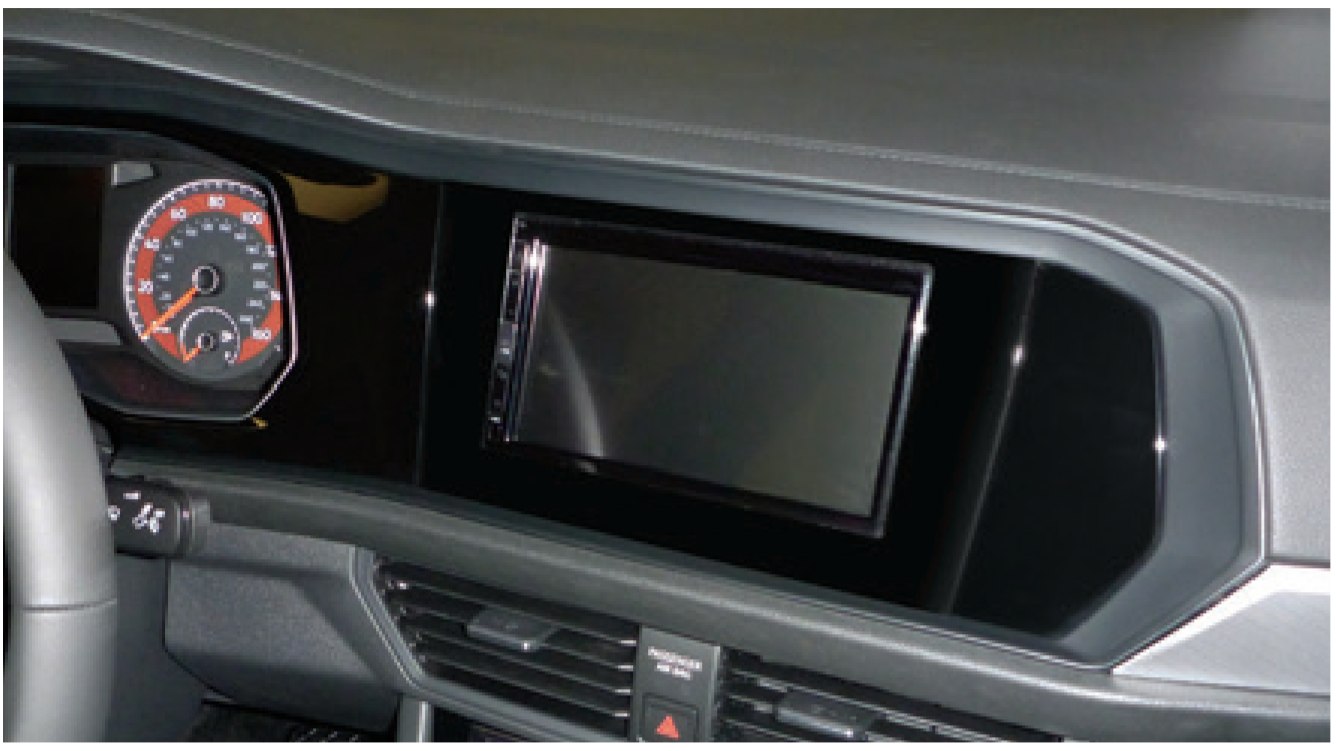
Metra Volkswagen Jetta2019-Up
KIT FEATURES
- ISO DIN radio provision
- ISO DDIN radio provision
- Pioneer modular DDIN radio provision
- Painted high gloss black to match the factory finish
† Only for with ISO DDIN radios which have an “L” shaped chassis design, with the radio chassis at the top of the screen. At present only the Sony XAV-AX100, XAV-AX200, and XAV-AX5000 radios have this design. The Pioneer modular radios, DMH-C2550NEX and DMH-C2500NEX, can also be used.
- A) Radio trim panel
- B) Radio brackets
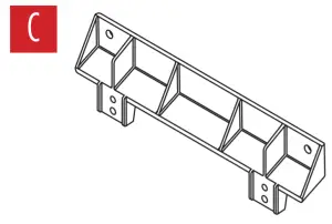
- C) Support bracket

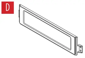
- D) Blank panel
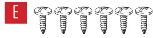
- E) #4 x 3/8″ Phillips pan-head screws (6)
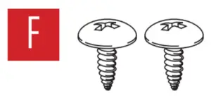
- F) #8 x 3/8″ Phillips truss-head screws (2)
- G) #8 x 1/2″ Phillips truss-head screws (4)
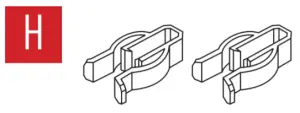
- H) Panel clips (2)
- I) Panel clip mounts (2)
WIRING & ANTENNA CONNECTIONS (sold separately)
Wiring Harness: AXTC-VW2Antenna Adapter: 40-EU56-36
TOOLS REQUIRED
- Panel removal tool
- Phillips screwdriver
- Cutting tool
- T-20 Torx driver
- VW radio removal tool (Metra part #86-9001)
| Attention! Let the vehicle sit with the key out of the ignition for a few minutes before removing the factory radio. When testing the aftermarket equipment, ensure that all factory equipment is connected before cycling the key to ignition. |
DASH DISASSEMBLY
- Open the driver’s door, then unclip and remove the dashboard side panel. (Figure A)
- Unclip and remove the trim panel directly below the far left a/c vent. Remove (1) T-20 Torx screw exposed. (Figure B)
- Unclip and remove the trim panel to the left of the steering column. (Figure C)
- Unclip and remove the trim panel directly below the far right a/c vent.Remove (2) T-20 Torx screws exposed. (Figure D)
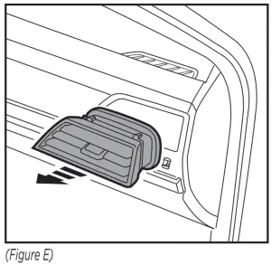
- Unclip and remove the far right a/c vent. (Figure E)
- Unclip and remove the trim panel above the glove box. Remove (3) T-20 Torx screws exposed, securing the radio & instrument trim panel. (Figure F,G)
- Unclip the top of the steering column shroud. The shroud is connected to the radio & instrument-cluster trim panel by a piece of material and will be removed fully in the following step. (Figure H)
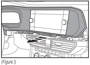
- Unclip and remove the radio & instrument-cluster trim panel, including the shroud loosened in the prior step. (Figure I)
- Using radio removal keys (sold separately), release the radio. Slide the radio out, then unplug and remove. Remove (2) metal clips attached to the sides of the radio for re-use in Kit Preparation. (Figure J)Note: This is just the display for the radio. The radio brain is located above the glove-box.
KIT PREPARATION
- Attach the factory metal clips removed in Dash Disassembly to the radio trim panel. (Figure A)
- For base model Jetta:Remove (5) Torx T-20 screws, then remove the radio support bracket. (Figure B)
- Secure the support bracket to the vehicle using (2) #8 x 1/2” Phillips trusshead screws provided. (Figure C)
- Secure the panel clip mounts to the radio trim panel using (4) #4 x 3/8” Phillips pan-head screws provided. (Figure D)
- Attach the (2) panel clips provided to the panel clip mounts. (Figure E)
KIT ASSEMBLY
ISO DIN radio provision
- Remove the metal DIN sleeve and trim ring from the aftermarket radio.
- Cut the radio brackets at the scored line. (Figure A)
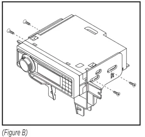
- Secure the radio brackets to the radio using screws supplied with the radio. (Figure B)
- Locate the factory wiring harness and antenna connector at the radio location above the glove-box. Complete all necessary connections to the radio.Metra recommends using the proper mating adapter from Metra and/ or Axxess. Test the radio for proper operation.
- Slide the radio assembly into the dash, then secure using (2) #8 x 1/2” Phillips truss-head screws up top, and (2) #8 x 3/8” Phillips truss-head down below.
- Secure the blank panel to the radio trim panel using (2) #4 x 3/8” Phillips pan-head screws provided. (Figure C)
- Clip the radio trim panel onto the radio assembly.
- Reassemble the dash in reverse order of disassembly to complete the installation.
ISO DDIN radio provision
- Cut the radio brackets at the scored line. (Figure A)
- Secure the radio brackets to the radio using screws supplied with the radio. (Figure B)
- Locate the factory wiring harness and antenna connector at the radio location above the glove-box. Complete all necessary connections to the radio.Metra recommends using the proper mating adapter from Metra and/ or Axxess. Test the radio for proper operation.
- Slide the radio assembly into the dash, then secure using (2) #8 x 1/2” Phillips truss-head screws up top, and (2) #8 x 3/8” Phillips truss-head down below.
- Clip the radio trim panel onto the radio assembly.
- Reassemble the dash in reverse order of disassembly to complete the installation.
Pioneer Modular DDIN radio provision
Note: For steps 1 and 2, reference the installation manual provided with the radio for which hardware to use. The display screen and radio chassis use two different types of screws.
- Secure the Pioneer radio display to the radio brackets using (4) screws supplied with the radio. (Figure A)
- Slide the Pioneer radio chassis between the radio brackets, then secure using (4) screws supplied with the radio. (Figure B)
- Locate the factory wiring harness and antenna connector at the radio location above the glove-box. Complete all necessary connections to the radio.Metra recommends using the proper mating adapter from Metra and/ or Axxess. Test the radio for proper operation.
- Slide the Pioneer radio assembly into the dash, then secure using (2) #8 x 1/2” Phillips truss-head screws up top, and (2) #8 x 3/8” Phillips truss-head down below.
- Clip the radio trim panel to the Pioneer radio assembly.
- Reassemble the dash in reverse order of disassembly to complete the installation.
 report this ad
If you are having difficulties with the installation of this product, contact our Tech Support line either by phone at 386-257-1187, or email at [email protected]. Before doing so, look over the instruction booklet a second time and ensure that the installation was performed exactly as the instruction booklet is stated. Have the vehicle apart and ready to perform troubleshooting steps before contacting Metra/Axxess Tech Support.
 |
KNOWLEDGE IS POWEREnhance your installation and fabrication skills by enrolling in the most recognized and respected mobile electronics school in our industry. Log onto www.installerinstitute.com or call 800-354-6782 for more information and take steps toward a better tomorrow |
|
Metra recommends MECP certified technicians |
References
[xyz-ips snippet=”download-snippet”]