EasyTouch 355Operating ManualRevision 1.8
The EasyTouch 355 model thermostats were designed to directly replace Coleman™, Airxcel™, and RVP™ ZC thermostats. Original thermostats must-have model numbers of 9330-333, 9330-334, 9330-335, 9330-336, or 9430-334 to be replaced by this thermostat. If your thermostat is not listed, please contact Micro-Air https://www.micro-air.com/SupportRequest to verify the thermostat you received is correct for your application.
Installing the thermostat
There are three steps to installing the thermostat.First, remove your old thermostat.Next, disconnect and reconnect the wiring.Finally, install the mounting pins to the wall and mount your new thermostat.Removing the old thermostatThe original thermostat is held to the wall with a backing plate that extends about ¼” (6.3mm) from the wall. The thermostat can be “popped off” the plate to access the mounting screws behind it.Remove the screws and unplug the two connections on the cable harness.Note, some thermostats are directly wired by the manufacturer. See the next section for further details.Wiring the thermostatNote: Early models of EasyTouch RV 355 thermostat have wires going from the thermostat to both interlocking connectors. See Appendix B for details on wiring this model. Later models have the ninepin connector mounted on the control board. This section will assist in wiring these models.Original thermostats can have a plug-in connector, or be direct-wired to the RV manufacturer’s wiring. Thermostats wired with a plug can simply unplug the original plug and plug in the EasyTouch thermostat.Micro-Air provides a connector to directly wire these thermostats to the wiring if the manufacturer has directly wired the thermostat. Match the original wiring colors to the provided EasyTouch connector colors to install the thermostat. See Table 1 for details on the colors used with the thermostat and the function of the wires.Note: See Appendix C: 9430-334 wiring for a different wiring table when replacing model number 9430334.Table 1
|
Original thermostat wire color |
Micro-Air harness color |
Function |
Factory harness color (Provided to write in your color) |
|
2- pinconnector |
Purple | Purple | Signal 1 |
| Black | Black | Signal 2 | |
|
9-pin connector |
Green | Green | Heat 4 |
| White | White | Heat 1 | |
| Blue | Blue | Ground in | |
| Red/white stripe | Red/white stripe | +12 VDC out | |
| Red | Red | + 12 VDC in | |
| Blue/White stripe | Blue/White stripe | Ground out | |
| Orange | Orange | Heat 2 | |
| Yellow | Yellow | Heat 3 |
Mounting the thermostat
Step 1: Locate the mounting buttons horizontally across the hole with a smaller diameter against the wall.
Step 2: Screw in one screw and level the buttons so the display will be straight when installed.
Step 3: Screw in the second screw making sure the two buttons remain level.
Step 4: Remove the mounting tab before mounting on the wall.
Step 5: Align the buttons with the holes in the back of the display. Press the display against the wall and gently slide the display down to lock it in place.
Initial setup instructions
Setting the available modesIt is necessary to set up the available modes prior to operating your thermostat. Press the settings button on the main screen. Select the available modes
button on the settings screen. Select cooling,
Gas heat,
or electric heat
![]() by pressing the icon. The red circle with a line through it will disappear indicating the mode is available. Available modes must match your original thermostat’s available modes. Use the zone button to set them appropriately for each available zone.Special model compatibilityThere is text in the available modes screen that reads “Normal” as shipped from Micro-Air.Pressing this text changes the operating modes to different options to support specific thermostats.Option A must be selected when replacing a thermostat with a model number of 9330-333.These models feature fan speed control of the roof fans in heating modes. Press the “Normal” text in the available modes screen to change the option to “Option A” when replacing this thermostat. Please note these systems used different control boards for this feature.Option B must be selected when replacing a thermostat with model number 9430-334. Press the “Normal” text in the available modes screen to change the text to “Option B” when replacing this thermostat. See Appendix C: 9430-334 wiring for more information on these systems.Connecting remotelyThis thermostat may be operated remotely using either Bluetooth or WIFI. Apps may be loaded from the Google Play Store or Apple App store. The first time the app is opened, it will ask to create an account. A WIFI connection on your smart device is necessary for this step. Create your account and follow the prompts to connect your thermostat.If a second user is going to use the thermostat remotely, they can use the same account and password as the first user. Each thermostat can only be assigned to a single account.
by pressing the icon. The red circle with a line through it will disappear indicating the mode is available. Available modes must match your original thermostat’s available modes. Use the zone button to set them appropriately for each available zone.Special model compatibilityThere is text in the available modes screen that reads “Normal” as shipped from Micro-Air.Pressing this text changes the operating modes to different options to support specific thermostats.Option A must be selected when replacing a thermostat with a model number of 9330-333.These models feature fan speed control of the roof fans in heating modes. Press the “Normal” text in the available modes screen to change the option to “Option A” when replacing this thermostat. Please note these systems used different control boards for this feature.Option B must be selected when replacing a thermostat with model number 9430-334. Press the “Normal” text in the available modes screen to change the text to “Option B” when replacing this thermostat. See Appendix C: 9430-334 wiring for more information on these systems.Connecting remotelyThis thermostat may be operated remotely using either Bluetooth or WIFI. Apps may be loaded from the Google Play Store or Apple App store. The first time the app is opened, it will ask to create an account. A WIFI connection on your smart device is necessary for this step. Create your account and follow the prompts to connect your thermostat.If a second user is going to use the thermostat remotely, they can use the same account and password as the first user. Each thermostat can only be assigned to a single account.
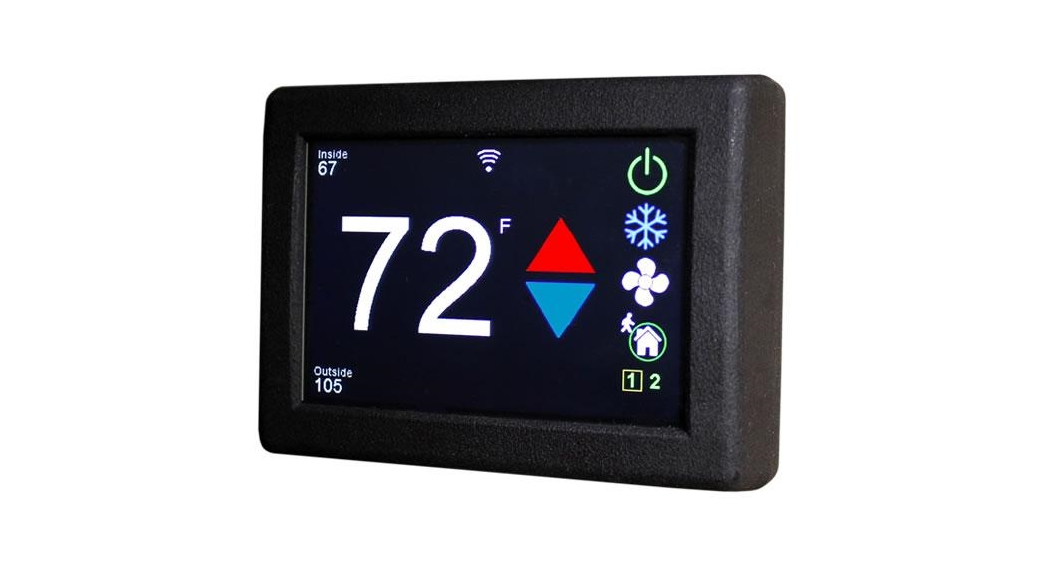
Operating the thermostat
Main screen
- Inside temperature shows the ambient temperature of the room.
- The WIFI indicator shows the state of the WIFI connection.Green indicates WIFI is connected properly, Red indicates a connection to the router only, bars indicate signal strength and no symbol indicates no connection.
- Raise and lower the temperature setpoint using the red and blue arrows.
- Use the power button to turn the system on or off.The button is red for off and green for on.

- Pressing the mode icon changes from cooling or heating modes depending on what is available in your system. See Table 2 for a list of all possible modes.
Fan only Automatic Cool Only Gas heating Zone off Electric Heating Zone on Table 2
- Pressing the fan icon selects between manual (always on) fan speeds and automatic fan speeds.Automatic will turn the fan off after the heating or cooling cycle is completed. See Table 3 for available fan speeds.
Available in mode
Indication Normal Option 1 Action
Manual fan low Manual fan, Cooling Manual fan, cooling, electric heat, gas heat The fan runs continually on low Manual fan high Manual fan, Cooling Manual fan, cooling, gas heat, electric heat The fan runs continually on high Auto fan Cooling, Auto Cooling, Auto Fan cycles with a compressor or electric element Auto fan low N/A Electric heat, gas heat The fan turns on low when heat is running Auto fan high N/A Electric heat, Gas heat The fan turns on high when heat is running Fan off N/A Gas heat The fan does not turn on when gas heating is active Note: Auto fan speed changes with temperature. More than 1 degree from the set point will run the high fan. The fan will run the low fan speed within one degree of the set point.
- Home-away-schedule icon. Pressing this button selects between these modes. Home mode is the normal operating mode using a single set point for temperature control. Schedule mode allows changing set points throughout the day programmatically. Away mode allows setting a heating and a cooling set point and automatically changing from heating to cooling.
- The zone selection button will show a zone in green when it is turned on. The zone number will show in gray if the zone is not available and in red if there is a fault with the zone. A frame will show around the zone number to indicate it is selected.
- Pressing the gear will change the settings screen to allow additional setup functions.
- Pressing the setpoint will change the system units from °F to °C and back. The setpoint is also used as an indicator of system operation. A red set point indicates a heating cycle is in process.A blue set point indicates a cooling cycle is in process. A white icon indicates no cycle is in process.


Away screen (Heat and cool setpoints)
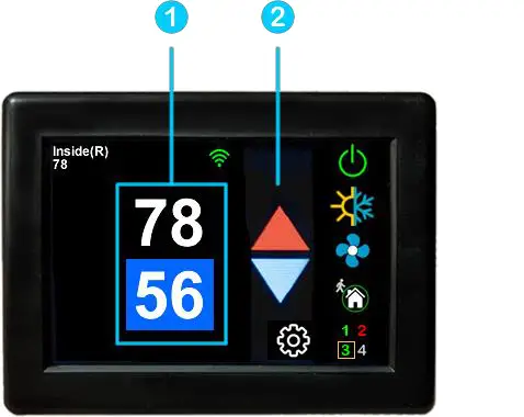
Away operation allows setting upper and lower limits for temperature with a non-operating area or “dead band” in the middle. This can be useful when setting a higher daytime cooling temperature and lower nighttime heating temperature. It can also be used to control the temperature extremes when you are away from the RV. The mode selected must be an automatic mode to allow both heating and cooling operation.
- Press the setpoints area to toggle between the selected values. A blue square will show around the value you are changing. The upper value changes the cooling set point and the lower value changes the heating setpoint.
- Use the up and down arrows to change the selected temperature value.
Schedule screen
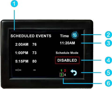
Setpoints may be changed on a time-based schedule. The mode used will be the heating or cooling mode set on the main screen.Setting a change event
- Events will show –:– when the event is disabled. Press the hour’s position to set the hours. A flashing bar will appear under the hours along with up and down adjustment selectors. Use the adjustment selectors to change the hours.Press the minutes to move the flashing bar under the minutes and allow ¼ hour adjustments.Use the up and down adjustment selectors to make changes.Press the temperature to change the desired temperature set point. This is the temperature the system will try to achieve after the time that was set.12- or 24-hour format
- Press the time in the upper right to change 12 and 24-hour time formats.Setting the time
- The Time zone is set and saved whenever the thermostat connects using Bluetooth. Time is set on power-up through the internet connection, or whenever a connection is made on either Bluetooth or WIFI.Enabling the schedule
- Press the enabled/disabled button to enable the schedule. The schedule will be active and make setpoint changes anytime the schedule is selected on the main screen. The Home/Schedule/Away button will only toggle between schedule and away when the schedule is enabled. The button will only select between home and away if the schedule is disabled. Away mode is not configurable on a schedule.
- Press the round arrow to return to the regular settings screen.
Settings Screen
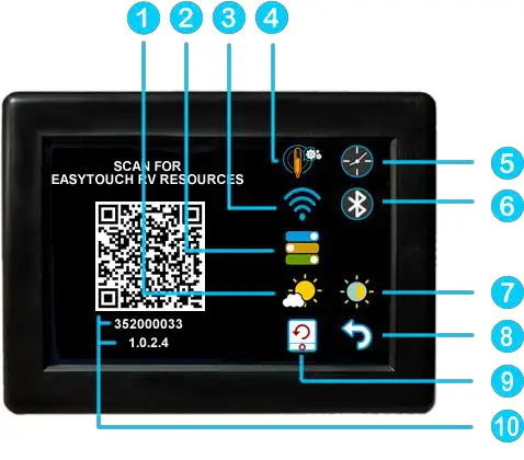
- Day/Night mode. Day mode (shown above) will dim the display down to the screen saver set point after 30 seconds. Night mode (moon icon) will turn off the backlight after 30 seconds. The display will brighten again once the touch screen is pressed. See (7) to set brightness.
- The DIP switches icon is used to configure the modes available in the thermostat. It must be used when installing the thermostat to set the available heat sources. See setting the available modes for more details.
- WIFI is used to view your WIFI settings and MAC address. Changes to the WIFI connection must be made using the smart device application.
- Temperature adjustment is used to adjust the inside temperature with an offset. This will only apply to zone 1.
- The schedule is used to change the setpoint automatically at a pre-determined time. See Schedule operation for more details.
- Bluetooth is used to reset the Bluetooth password. This password is saved from your account password. Only one account at a time may access the thermostat. Reset the password whenever you change your account password.
- Brightness settings allow dimming the normal brightness and setting the screen saver brightness.
- The back icon will return the display to the operating screen.
- Reset all will reset the thermostat to factory settings including all set points, schedule events, and other settings.
- The QR code will bring you to the Micro-Air EasyTouch page when selected using a QR-compatible phone app. Below the QR code is the serial number for the thermostat and the firmware revision for the thermostat. Firmware updates can be checked for in the smart device application.
Gas Heat OverrideThis feature turns on the gas furnace from an electric heat mode when the setpoint is five or mode degrees away from the ambient temperature and heating is required. It is only available on systems that have both gas and electric heating and is only active in electric heat or cool/electric heat modes.If the heating setpoint is 5 degrees or more above the inside temperature in an electric heating mode, the furnace will come on along with the electric heater. Both will remain on until the setpoint is reached. If this action is necessary more than twice in a row, gas heat will be used for the next two hours without electric heating. This is indicated by a red circle and line through the electric mode button.When the furnace is actively overriding the electric heat, a furnace symbol will appear at the top of the thermostat screen.
Smart device application only features
Reset deviceThis Bluetooth-only feature allows resetting the display just as if you removed and restored power.Calibrate Touchscreen It is normally not necessary to recalibrate the touchscreen. This selection prompts the user to press the four corners of the display then test the calibration using three diagonal marks. This feature is only available from Bluetooth.Check for updatesCheck to see if any updates are available for the thermostat. The smart device application must have internet and the thermostat must be connected to WIFI with a green WIFI symbol. Tap Check for Updates and follow the prompts.NotificationsNotifications provide a way for the thermostat to communicate back to a smart device like a tablet or phone. These notifications are indications of the temperature exceeding a set limit. Limits are set by connecting to the thermostat in the app, selecting the settings gear, and then selecting notifications. A minimum and maximum allowed temperature can be set. Table 4 shows an example of an operation with an 80°F maximum temperature set. Notification will be sent for each degree it rises above the maximum temperature. If the temperature drops, no notification will be sent unless the temperature exceeds the last maximum temperature again (82 in the example). If the temperature drops two degrees below the set maximum, (78 in the example) it will again alert for each degree above the set maximum. This behavior helps avoid nuisance notifications to your smart device.Table 4
| Temperature °F | Action |
| 80 | Send first notification |
| 81 | Send another notification |
| 82 | Send another notification |
| 81…79 | The temperature drops, no notification |
| 78 | Max temp resets |
Appendix A: Installation Troubleshooting
The most common problem is not knowing the thermostat operation. If the system is running a heating or cooling cycle, the setpoint will turn red for heating and blue for cooling. When the thermostat turns white, the heat pump, heat strip, and furnace should all be off. The fan may continue to run for a while after the cycle completes. If a fan is left in manual mode, it will not shut off.
WIFI Troubleshooting
No WIFI Icon
- SSID (Network name) and password are both cases sensitive.
- Be sure you are connecting to a 2.4 GHz network and not a 5GHz or 6GHz network.
- Set the security to WPA2 and TKIP+AES if you are having trouble.
- The thermostat has a limit of 31 characters for the SSID and 50 for the password.
- The number of devices limit for the network is not full.
- The WIFI source is not out of range or metal partitions blocking the signal
- Reset the router to renew the DHCP lease.
- If you are in a metal enclosure, try moving the router or thermostat a few inches (even if temporary) and trying again.
- If using MAC filtering, add the thermostat to the allowed devices list.
Red WIFI Icon
- The router must have an internet connection
- The server may be down, check back at a later time
- Be sure there is no firewall in the router blocking the incoming messages (port 443, HTTPS).
Appendix B: Connecting remotely
First connection steps
- This thermostat uses BLE which is a special implementation of Bluetooth. It is not necessary to “Pair” the thermostat with the phone but an account must be created for operation.
- Start the app on your smart device. The app will open and if you have not entered your account information, it will ask you to create an account. Enter your name, email, and password at the prompts. The system will send a confirmation email to your inbox. Enter the number in the confirmation email when asked.
- Once the account is created, the application may ask to add a device. If your device is powered it will show in the list to be added to your account. Select the control and enter a name or location for the control.
- If you added control, the app will ask if you want to connect to WIFI now. Enter your SSID (network name) and password in the boxes.
Adding a controlFollow the next steps if the accounting process does not add a control or a second thermostat is to be added.
- Press “Add” on the top of the selection screen (Apple) or press the settings gear and “Add Device” (Android).
- The second thermostat should be listed in the new selection window. Select the device and enter the name of the device.
- Press OK and the screen will return to the settings menu (Android) or the selection screen (Apple). Android users should press the back button to get to the selection screen.
- Select the device name to open the thermostat screen.
Connecting to a new WIFI network
- Connect to the thermostat in Bluetooth (Apple) and press the settings gear.
- Select WIFI Setup from the settings window.
- Enter the SSID (network name) and password (Both case sensitive).
- Press OK and the screen will return to the selection screen. The thermostat will reset and a green WIFI symbol will appear on the thermostat screen if the connection was successful.
Updating the thermostatEnsuring you have the latest thermostat software is key to having all the latest features.
- Ensure the thermostat is connected to WIFI with a green WIFI symbol.
- Connect to the thermostat and press the settings gear, then tap Check for Updates.
- Follow the prompts to update the thermostat or ensure that you already have the latest software.
Appendix C: 9430-334 wiring
 report this ad
Table 5
| Original thermostat wire color | Micro-Air harness color | Function |
Factory harness color (Provided to write in your color) |
| Purple | Purple | Signal 1 | |
| Black | Black | Signal 2 | |
| Green | Green | Zone 2 On | |
| White | White | Zone 1 High | |
| Blue | Blue | Ground in | |
| Red/white stripe | Red/white stripe | +12 VDC out | |
| Red | Red | + 12 VDC in | |
| Blue/White stripe | Blue/White stripe | Ground out | |
| Orange | Orange | Zone 2 High | |
| Yellow | Yellow | Zone 1 On |
Table 5 shows the wiring functions used for this model thermostat. Option B must be selected in the settings’ switches menu. Only two heating zones are possible in this configuration. Yellow and green are used to turn on single-stage furnaces for zones 1 and two respectively. This can be used in Aqua hot systems as well to turn on each of the two zones for heating.Two-stage furnaces like certain suburban models use orange and white wires to turn on the high furnace fan and high gas valve. This feature activates a high furnace if the ambient temperature is more than four degrees below the set point.
©2021 Micro-Air CorpJuly 1, 2021, revision 1.8
[xyz-ips snippet=”download-snippet”]