Micro-Air EasyTouch RV Thermostat Installation Guide
Important Safety Information
- CAUTION: Voltages inside air conditioning equipment are potentially lethal. Turn off all power to the equipment before installing or servicing the thermostat.
- RV systems can have multiple power sources that all must be disabled or turned off before installation. Power sources can include AC line or shore power, generators, inverters, batteries, vehicle connections, and solar energy. Be sure to inhibit or disconnect all sources before installation. Contact your RV manufacturer if you are not sure how to disable these systems.
- Do not reconnect or reapply power sources until the installation is completed.
- Read and retain instructions: Read all the safety and operating instructions associated with your equipment before installing and operating this device. Retain this documentation for future reference.
- Heed warnings: Adhere to all warnings and precautions listed in the operating instructions.
- Manufacturer cautions: These precautions do not replace manufacturer cautions given by the original equipment manufacturer. Read and follow all manufacturer guidelines related to the connected equipment.
- Follow instructions: Follow all operating instructions.
- Water: Do not expose this device to any dripping or splashing water. Do not expose to condensing humidity.
- Cleaning: Wipe the surfaces with a soft cloth only to prevent scratches. Do not use solvents as they may damage the device.
- CAUTION: Voltages inside the connected device are potentially lethal. Turn off all power to the device before installing or servicing the equipment.
- Ventilation: Install the device where adequate ventilation can be achieved.
- Heat: keep device away from heat sources that can adversely affect its operation.
- Grounding: Follow all applicable local guidelines for electrical safety regarding grounds.
- Moisture: Never operate or store this thermostat in a wet or condensing environment.
- Servicing: The user should not attempt to service this device beyond what is described in this manual. All other servicing should be referred to the factory or a qualified service person.
- Eye wear: Always wear eye protection when drilling holes for installation.
- Disassembly: There is no reason to disassemble our EasyTouch RV thermostat. Disassembly voids the product warranty. Wall mounting is made externally.
- Safe installation: Read this Manual for your display and use the provided installation screws and mounting bracket/template.
Installation
All installations are made via an external wall mount. Do not open your EasyTouch RV thermostat.
Single Zone DC (ASY-352)
Includes all Coleman™, Airxcel™, and RV Products™ (RVP) units except ZC and dual stage
- Push up gently on the bottom of the original thermostat. The thermostat will snap up and then can be removed from the wall.
- A. Models that have connectors on a short wire harness: Unplug the thermostat and remove it fromthe wall.
- 2B. Models with directly connected wires: Take a picture of the wiring so it can be matched to your new thermostat. Some installations may be able to move one wire at a time to the new thermostat.
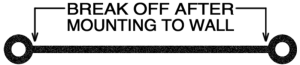
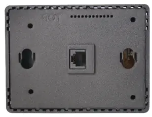
- Use the mounting template to locate and drill two 3/16” (4.76mm) holes. Insert the wall anchors into the holes. Place the plastic mounting bracket against the wall with the smaller side closest to the wall. Screw the wall mounting bracket into the wall anchors using the provided screws. Remove the center plastic spacer after the screws are tight.
- A. Models with connectors on a short harness can plug EasyTouch RV into the harness.
- B. Models with directly connected wires should connect the wires using the wiring order from the original thermostat. Match the wire label to the same label on the EasyTouch RV thermostat.

- Insert the thermostat mounting pins into the back of the thermostat in the provided holes while pressing it against the wall. Press down gently with the thermostat flush against the wall to lock down the thermostat.

Multi-Zone OEM (ASY-350)
Includes Dometic™ Multi-zone CCC2 systems only
- Press up on the tab located on the bottom of the original Dometic™ thermostat with a small screw driver and tilt the base of the display toward you to remove the thermostat faceplate.
- Remove the four mounting screws from the thermostat.
- Unplug the original thermostat from the cable. Press the small tab toward the cable and gently pull out the connector.
- Use the mounting template to locate and drill two 3/16” (4.76mm) holes. Insert the wall anchors into the holes. Place the plastic mounting bracket against the wall with the smaller side closest to the wall. Screw the wall mounting bracket into the wall anchors using the provided screws. Remove the center plastic spacer after the screws are tight.
- Plug the thermostat cable into the EasyTouch RV thermostat.
- Insert the thermostat mounting pins into the back of the thermostat in the provided holes while pressing it against the wall. Press down gently with the thermostat flush against the wall to lock down the thermostat.
Single-Zone OEM (ASY-351)
Includes Dometic™ Single zone systems only
- Press up on the tab located on the bottom of the original Dometic™ thermostat with a small screw driver and tilt the base of the display toward you to remove the thermostat faceplate.
- Take a picture of the three wires connected inside the thermostat. Disconnect the three wires.
- Remove the four mounting screws from the thermostat and completely remove the thermostat.
- Use the mounting template to locate and drill two 3/16” (4.76mm) holes. Insert the wall anchors into the holes. Place the plastic mounting bracket against the wall with the smaller side closest to the wall. Screw the wall mounting bracket into the wall anchors using the provided screws. Remove the center plastic spacer after the screws are tight.
- Connect 12V- to GND, COMMS to SIG, and 12V+ to 12V from the previously disconnected wires.
- Insert the thermostat mounting pins into the back of the thermostat in the provided holes while pressing it against the wall. Press down gently with the thermostat flush against the wall to lock down the thermostat.

Operation
Image Icons
Image icons are displayed on your screen as touch/press areas. A complete list of them is provided in Appendix I of this document. They are organized to show related icons with functions described in the text below. We recommend setting the home, away, or schedule operation first. Next set the desired operating mode such as cool only or a heating mode. Finally set the fan speed and desired set point.
Basic operations
![]() The power button icon on the top right of the thermostat turns the system off and on. Additional settings and scheduled temperature changes are available when the thermostat is off.
The power button icon on the top right of the thermostat turns the system off and on. Additional settings and scheduled temperature changes are available when the thermostat is off.
![]() Cool, heat strip, heat pump, and furnace-aqua modes are available based on system configuration. Press the image icon to select a different operating mode.
Cool, heat strip, heat pump, and furnace-aqua modes are available based on system configuration. Press the image icon to select a different operating mode.
![]() Automatic modes switch between cooling and the chosen heating mode as required to maintain temperature. These modes are available based on the heating modes offered by your system.
Automatic modes switch between cooling and the chosen heating mode as required to maintain temperature. These modes are available based on the heating modes offered by your system.
![]() Fan speed can be selected between low and high, medium (if available), and automatic. Automatic changes fan speeds as required for improved comfort.
Fan speed can be selected between low and high, medium (if available), and automatic. Automatic changes fan speeds as required for improved comfort.
![]() Home, away, and schedule functions provide three different thermostat experiences.
Home, away, and schedule functions provide three different thermostat experiences.
- Home: Traditional way a thermostat operates, changing at a specific setpoint.
- Away: Provides two set points allowing a wider range of temperatures. Set your desired auto mode, if available.
- Schedule: Allows changing the temperature up to four times each day.
Adjusting the brightness
The display automatically dims after 25 seconds without a touch. There are two dimming modes selectable for this feature. Day mode shows the screen but at a dimmer setting. Night mode completely turns off the screen while still functioning. Brightness adjustment is available for day mode. A touch will return the screen to active brightness.
Using the schedule
Schedule entries must be created before using the schedule. Press the power icon to turn the control off then press the schedule icon. Set up to four times and temperature changes in the change area under the 12/24-hour selection. –:– indicates not enabled. Press the time or –:– and a blue box will appear over the value. Use the up and down arrows to make the adjustment. Press the power icon when you are finished editing the times to save and exit the schedule. Press the home or away icon on the main screen until the schedule icon appears. This activates the schedule. The schedule temperature can be temporarily overridden by changing the set point. It will change the setpoint back at the next scheduled change.
Changing temperature units
Tap the set point temperature on the screen to change the temperature units from Celsius to Fahrenheit and back again.
Smart device applications
iPhone™ and Android™ applications are hosted by and available in the Apple App Store and from Google Play. They can be found by searching those stores for EasyTouch RV™ and making the free download to your phone.
Creating your account
Smart device application requires an account be created to access the device. Creating the account requires internet access on the smart device. If this is your first time using a Micro-Air device, create a new account. If you are adding a second phone or tablet, you can just sign in with your existing account and the control list will be imported for you.
Connecting with Bluetooth
Use Bluetooth whenever you are in range of your thermostat. For most users this will be up to 130 feet (40 meters). Your distance will vary depending on mounting and other conditions.
Adding your thermostat to the account
Your smart device must have internet access to add a device. Select Bluetooth and select “Add” at the top of the screen. If your thermostat is powered and operating, an entry will appear in the list for “EasyTouch nnnnnnnnn” where n is the device serial number. Select your device from the available device list. If no devices appear, try moving closer to the device or cycling power on the Micro-Air device. Give the device a name and press save to add the device. The screen will return to the selection window and you can now select the device to operate it.
Removing a device
Your smart device must be connected to the internet to remove a device. Swipe the device to the left (Apple) or press the garbage can (Android) to remove the device.
Resetting the Bluetooth password
Connecting to Bluetooth for the first time sets your account password as the device password. If you change your account password you must reset the Bluetooth password at the thermostat. Press the power icon to turn the control off, then press the Settings icon. Press the Bluetooth icon, then press the green check box to reset the password.
Connect the device to the internet
Select Bluetooth and select your thermostat. When the thermostat connects, select settings from the top of the screen. Select Connect to WIFI (Android) or Edit WIFI settings (Apple). Enter your network name (SSID) and password. The device will reset and connect to the internet on reset. The smart device will return to the selection screen when the signal is lost.
Connecting with WIFI
Use WIFI whenever you are not within Bluetooth range of your thermostat. A connection requires only that the thermostat and the smart device have internet connections and are connected to the account.
Calibrating the touchscreen
Each time the display is powered on it will go through a reset process and display the Micro-Airlogo. Touching the logo will cause the display to enter the calibration screen. Follow the on-screen instructions to complete calibration.
Note: The display may be reset without removing power by re-entering the SSID and password for your network from the Bluetooth settings screen. This will reset the display and show the Micro-Air logo again.
Appendix I: Image reference
System Off
- System off. Press to turn on system.
- Zone off. Press to turn on zone.
- Open settings menu.
- Open schedule menu.
System On
- Indicates system is active and working in the mode selected.
- Cooling only mode. Uses compressor to provide cooling.
- Heat pump mode (1). Uses compressor to provide heating.
- Heat strip mode (1). Uses heat strip to provide heating.
- Furnace mode (1). Uses furnace to provide heating.
- Cool and furnace mode (1). Uses compressor for cooling and furnace for heating.
- Cool and heat pump mode (1). Uses compressor for both heating and cooling.
- Cool and heat strip mode (1). Uses compressor for cooling and heat strip for heating.
- Low fan speed.
- High fan speed.
- Automatic selection between low and high fan speeds. Fan is off at setpoint, on low speed within 5°F (2.8°C) of set point, and high otherwise.
- Home mode. Thermostat operates based on selected set point.
- Away mode. Thermostat operates heating and/or cooling based on the upper and lower limits the user sets.
- Schedule mode. Operates like the home mode but will change the set point at specific times of day set in the schedule.
Note:
- Heating modes available are based on the system the thermostat is connected to. Only available heating modes will be displayed.
Settings
- Calibrate the displayed temperature by up to 10°F (5.5°C).
- Adjust the furnace or Aqua system temperature change to either 1° or 2°.
- Use WPS to connect to a router or connect the display to an account.
- Reset the Bluetooth password.
- View the system heating options.
- Select the day or night screen brightness.
- Set the display brightness for day or night.
- Reset the display to factory defaults.
- Return to the last screen.
Warranty
LIMITED WARRANTY
Micro-Air expressly warrants new products made by it to be free from manufacturing defects for a period of two (2) years from the date of delivery to the original purchaser of our product (“Purchaser”). Complete details of the Warranty may be found at https://www.microair.net/pages/legal.
Copyright ©2020 Micro-Air Inc.
No part of this publication may be reproduced, translated, stored in a retrieval system, or transmitted in any form or by any means electronic, mechanical, photocopying, recording or otherwise without prior written consent by Micro-Air, Inc. Every precaution has been taken in the preparation of this manual to ensure its accuracy. However,
 report this ad
Micro-Air Inc. assumes no responsibility for errors and omissions. Neither is any liability assumed nor implied for damages resulting from the use or misuse of this product and information contained herein.
References
[xyz-ips snippet=”download-snippet”]