Digital Console for Live and Studio with 40 Input Channels, 16 MIDAS PRO
Important Safety Instructions
Caution
- Terminals marked with this symbol carry electrical current of sufficient magnitude to constitute risk of electric shock.
- Use only high-quality professional speaker cables with ¼” TS or twist-locking plugs pre-installed. All other installation or modification should be performed only by qualified personnel.
- This symbol, wherever it appears, alerts you to the presence of uninsulated dangerous voltage inside the enclosure – voltage that may be sufficient to constitute a risk of shock.
- This symbol, wherever it appears, alerts you to important operating and maintenance instructions in the accompanying literature. Please read the manual.
- To reduce the risk of electric shock, do not remove the top cover (or the rear section). No user serviceable parts inside. Refer servicing to qualified personnel.
- To reduce the risk of fi re or electric shock, do not expose this appliance to rain and moisture. The apparatus shall not be exposed to dripping or splashing liquids and no objects filled with liquids, such as vases, shall be placed on the apparatus.
- These service instructions are for use by qualified service personnel only. To reduce the risk of electric shock do not perform any servicing other than that contained in the operation instructions. Repairs have to be performed by qualified service personnel.
- Read these instructions.
- Keep these instructions.
- Heed all warnings.
- Follow all instructions.
- Do not use this apparatus near water.
- Clean only with dry cloth.
- Do not block any ventilation openings. Install in accordance with the manufacturer’s instructions.
- Do not install near any heat sources such as radiators, heat registers, stoves, or other apparatus (including amplifiers) that produce heat.
- Do not defeat the safety purpose of the polarized or grounding-type plug. A polarized plug has two blades with one wider than the other. A grounding-type plug has two blades and a third grounding prong. The wide blade or the third prong are provided for your safety. If the provided plug does not fi t into your outlet, consult an electrician for replacement of the obsolete outlet.
- Protect the power cord from being walked on or pinched particularly at plugs, convenience receptacles, and the point where they exit from the apparatus.
- Use only attachments/accessories specified by the manufacturer.
- Use only with the cart, stand, tripod, bracket, or table specified by the manufacturer, or sold with the apparatus. When a cart is used, use caution when moving the cart/apparatus combination to avoid injury from tip-over.
- Unplug this apparatus during lightning storms or when unused for long periods of time.
- Refer all servicing to qualified service personnel. Servicing is required when the apparatus has been damaged in any way, such as power supply cord or plug is damaged, liquid has been spilled or objects have fallen into the apparatus, the apparatus has been exposed to rain or moisture, does not operate normally, or has been dropped.
- The apparatus shall be connected to a MAINS socket outlet with a protective earthing connection.
- Where the MAINS plug or an appliance coupler is used as the disconnect device, the disconnect device shall remain readily operable.
- Correct disposal of this product: This symbol indicates that this product must not be disposed of with household waste, according to the WEEE Directive (2012/19/EU) and your national law. This product should be taken to a collection center licensed for the recycling of waste electrical and electronic equipment (EEE). The mishandling of this type of waste could have a possible negative impact on the environment and human health due to potentially hazardous substances that are generally associated with EEE. At the same time, your cooperation in the correct disposal of this product will contribute to the efficient use of natural resources. For more information about where you can take your waste equipment for recycling, please contact your local city office, or your household waste collection service.
- Do not install in a confined space, such as a book case or similar unit.
- Do not place naked flame sources, such as lighted candles, on the apparatus.
- Please keep the environmental aspects of battery disposal in mind. Batteries must be disposed-of at a battery collection point.
- Use this apparatus in tropical and/or moderate climates.
LEGAL DISCLAIMER
MUSIC Tribe accepts no liability for any loss which may be suffered by any person who relies either wholly or in part upon any description, photograph, or statement contained herein.Technical specifications, appearances and other information are subject to change without notice.All trademarks are the property of their respective owners. MIDAS, KLARK TEKNIK, LAB GRUPPEN, LAKE, TANNOY, TURBOSOUND, TC ELECTRONIC, TC HELICON, BEHRINGER, BUGERA and COOLAUDIO are trademarks or registered trademarks of MUSIC Group IP Ltd.© MUSIC Group IP Ltd. 2018 All rights reserved.
LIMITED WARRANTY
For the applicable warranty terms and conditions and additional information regarding MUSIC Tribe’sLimited Warranty, please see complete details online at music-group.com/warranty.
Important information
- Register online. Please register your new MUSIC Tribe equipment right after you purchase it by visiting midasconsoles.com. Registering your purchase using our simple online form helps us to process your repair claims more quickly and efficiently. Also, read the terms and conditions of our warranty, if applicable.
- Malfunction. Should your MUSIC Tribe Authorized Reseller not be located in your vicinity, you may contact the MUSIC Tribe Authorized Fulfiller for your country listed under “Support” at midasconsoles.com. Should your country not be listed, please check if your problem can be dealt with by our “Online Support” which may also be found under “Support” at midasconsoles.com.Alternatively, please submit an online warranty claim at midasconsoles.com BEFORE returning the product.
- Power Connections. Before plugging the unit into a power socket, please make sure you are using the correct mains voltage for your particular model.Faulty fuses must be replaced with fuses of the same type and rating without exception.
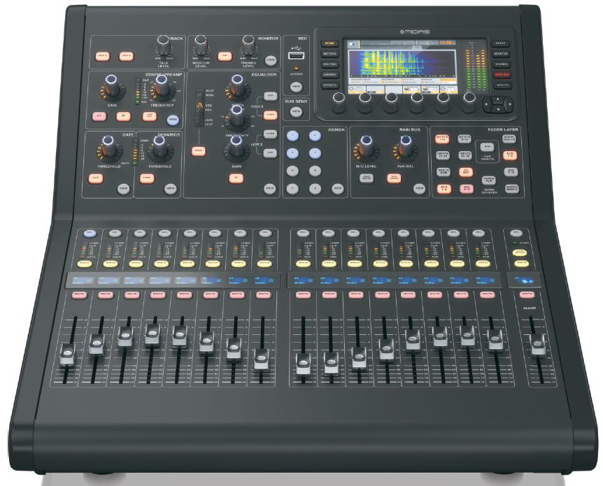
Control Surface

- CONFIG/PREAMP – Adjust the preamp gain for the selected channel with the GAIN rotary control. Press the 48 V button to apply phantom power for use with condenser microphones and press the Ø button to reverse the channel’s phase. The LED meter displays the selected channel’s level. Press the LOW CUT button and select the desired high-pass frequency to remove unwanted lows. Press the VIEW button to access more detailed parameters on the Main Display.
- GATE/DYNAMICS – Press the GATE button to engage the noise gate and adjust the threshold accordingly. Press the COMP button to engage the compressor and adjust the threshold accordingly. When the signal level in the LCD meter drops below the selected gate threshold , the noise gate will silence the channel. When the signal level reaches the selected dynamics threshold, the peaks will be compressed. Press the VIEW button to access more detailed parameters on the Main Display.
- EQUALISER – Press the EQ button to engage this section. Select one of the four frequency bands with the LOW, LO MID, HI MID and HIGH buttons. Press the MODE button to cycle through the types of EQ available. Boost or cut the selected frequency with the GAIN rotary control. Select the specific frequency to be adjusted with the FREQUENCY rotary control and adjust the bandwidth of the selected frequency with the WIDTH rotary control. Press the VIEW button to access more detailed parameters on the Main Display.
- TALKBACK – Connect a talkback microphone via a standard XLR cable via the EXT MIC socket. Adjust the level of the talkback mic with the TALK LEVEL rotary control. Select the destination of the talkback signal with the TALK A/TALK B buttons. Press the VIEW button to edit the talkback routing for A and B.
- MONITOR – Adjust the level of the monitor outputs with the MONITOR LEVEL rotary control. Adjust the level of the headphones output with the PHONES LEVEL rotary control. Press the MONO button to monitor the audio in mono. Press the DIM button to reduce the monitor volume. Press the VIEW button to adjust the amount of attenuation along with all other monitor-related functions.
- RECORDER – Connect an external memory stick to install firmware updates, load and save show data, and to record performances. Press the VIEW button to access more detailed Recorder parameters on the Main Display.
- BUS SENDS – Press this button to access detailed parameters on the Main Display. Quickly adjust the bus sends by selecting one of the four banks, followed by one of the corresponding rotary controls under the Main Display.
- MAIN BUS – Press the MONO CENTER or MAIN STEREO buttons to assign the channel to the main mono or stereo bus. When MAIN STEREO (stereo bus) is selected, the PAN/BAL adjusts to the left-to-right positioning. Adjust the overall send level to the mono bus with the M/C LEVEL rotary control. Press the VIEW button to access more detailed parameters on the Main Display.
- MAIN DISPLAY – The majority of the M32R’s controls can be edited and monitored via the Main Display. When the VIEW button is pressed on any of the control panel functions, it is here that they can be viewed. The main display is also used for accessing the 60+ virtual effects. See section 3. Main Display.
- ASSIGN – Assign the four rotary controls to various parameters for instant access to commonly-used functions. The LCD displays provide quick reference to the assignments of the active layer of custom controls. Assign each of the eight customASSIGN buttons (numbered 5-12) to various parameters for instant access to commonly used functions. Press one of the SET buttons to activate one of the three layers of custom assignable controls. Please refer to the User Manual for more details on this topic.
- LAYER SELECT – Pressing one of the following buttons selects the corresponding layer on the appropriate channel:• INPUTS 1-8, 9-16, 17-24 & 25-36 – the first, second, third and fourth blocks of eight channels assigned on the ROUTING / HOME page• FX RET – allows you to adjust the levels of the effects returns.• AUX IN / USB – the fifth block of six channels & USB Recorder, and eight channel FX returns (1L …4R)• BUS 1-8 & 9-16 – this allows you to adjust the levels of the 16 Mix Bus Masters, which is useful when including Bus Masters into DCA Group assignments, or when mixing buses to matrices 1-6• REM – DAW Remote Button – Press this button to enable remote control of your Digital Audio Workstation software using the Group/Bus fader section controls. This section can emulate HUI or Mackie Control Universal communication with your DAW• FADER FLIP – SENDS ON FADER Button – Press to activate the M32R’s Sends on Fader function. See Quick Reference (below) or the User Manual for more details.Press any of the above buttons to switch the input channel bank to any of the four layers listed above. The button will illuminate to show which layer is active.
- INPUT CHANNELS – The Input Channels section of the console offers eight separate input channel strips. The strips represent four separate layers of input for the console, which can each be accessed by pressing one of the buttons in the LAYER SELECT section. You will fi nd a SEL (select) button on top of every channel which is used to direct the control focus of the user’s interface, including all channel-related parameters to that channel. There is always exactly one channel selected.The LED display shows the current audio signal level through that channel.The SOLO button isolates the audio signal for monitoring that channel.The LCD Scribble Strip (which can be edited via the Main Display) shows the current channel assignment.The MUTE button mutes the audio for that channel.
- GROUP/BUS CHANNELS – This section offers eight channel strips, assigned to one of the following layers:• GROUP DCA 1-8 – Eight DCA (Digitally Controlled Amplifier) groups• BUS 1-8 – Mix Bus masters 1-8• BUS 9-16 – Mix Bus Masters 9-16• MTX 1-6 / MAIN C – Matrix Outputs 1-6 and the Main Centre (Mono) bus.The SEL, SOLO & MUTE buttons, the LED display, and the LCD scribble strip all behave in the same way as for the INPUT CHANNELS.
- MAIN CHANNEL – This controls the Master Output stereo mix bus.The SEL, SOLO & MUTE buttons, and the LCD scribble strip all behave in the same way as for the INPUT CHANNELS.The CLR SOLO button removes any solo functions from any of the other channels.
Please refer to the User Manual for more information on each of these topics.
Rear Panel
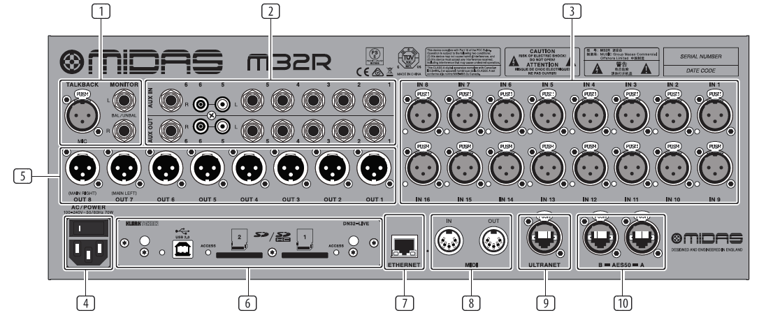
- MONITOR/CONTROL ROOM OUTPUTSconnect a pair of studio monitors using XLR or ¼” cables. Also includes a 12 V / 5 W lamp connection.
- AUX IN/OUT – Connect to and from external equipment via ¼” or RCA cables.
- INPUTS 1 – 16 – Connect audio sources (such as microphones or line level sources) via XLR cables.
- POWER – The IEC mains socket and ON/OFF switch.
- OUTPUTS 1 – 8 – Send analogue audio to external equipment using XLR cables. Outputs 15 and 16 by default carry the main stereo bus signals.
- DN32-LIVE INTERFACE CARD – Transmit up to 32 channels of audio to and from a computer via USB 2.0, as well as record up to 32 channels to SD/SDHC cards.
- REMOTE CONTROL INPUTS – Connect to a PC for remote control via Ethernet cable.
- MIDI IN/OUT – Send and receive MIDI commands via 5-pin DIN cables.
- ULTRANET – Connect to a personal monitoring system, such as the BEHRINGER P16, via Ethernet cable.
- AES50 A/B – Transmit up to 96 channels in and out via Ethernet cables.
Please refer to the User Manual for more information on each of these topics.
Main Display
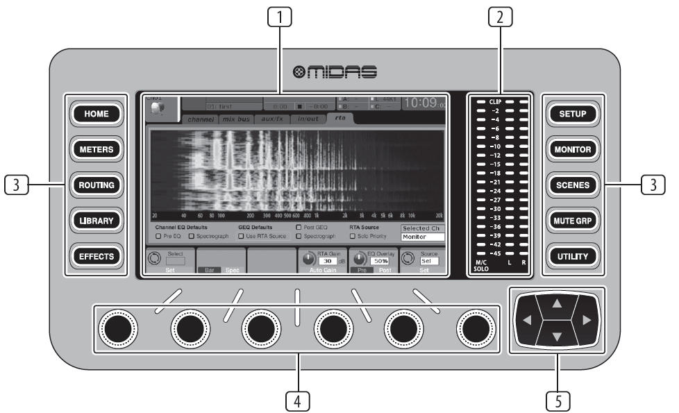
DISPLAY SCREEN
The controls in this section are used in conjunction with the colour screen in order to navigate and control the graphical elements it contains.By including dedicated rotary controls that correspond to the adjacent controls on the screen, as well as including cursor buttons, the user can quickly navigate and control all of the colour screen’s elements.The colour screen contains various displays that give visual feedback for the operation of the console, and also allow the user to make various adjustments not provided for by the dedicated hardware controls.
MAIN/SOLO METERS
This triple 24-segment meter displays the audio signal level output from the main bus, as well as the main centre or solo bus of the console.
SCREEN SELECTION BUTTONS
These eight illuminated buttons allow the user to immediately navigate to any of the eight master screens that address different sections of the console. The sections that can be navigated are:
• HOME – The HOME screen contains an overview of the selected input or output channel, and offers various adjustments not available through the dedicated top panel controls.The HOME screen contains the following separate tabs:home: General signal path for the selected input or output channel.config: Allows selection of the signal source/destination for the channel, configuration of insert point, and other settings.gate: Controls and displays the channel gate effect beyond those offered by the dedicated top-panel controls.dyn: Dynamics – controls and displays the channel dynamics effect (compressor) beyond those offered by the dedicated top-panel controls.eq: Controls and displays the channelEQ effect beyond those offered by the dedicated top-panel controls. sends: Controls and displays for channel sends, such as sends metering and send muting. main: Controls and displays for the selected channel’s output.
• METERS – The meters screen displays different groups of level meters for various signal paths, and is useful for quickly ascertaining if any channels need level adjustment. Since there are no parameters to adjust for the metering displays, none of the metering screens contain any ‘bottom of the screen’ controls that would normally be adjusted by the six rotary controls.The METER screen contains the following separate screen tabs, each containing level meters for the relevant signal paths: channel, mix bus, aux/fx, in/out and rta.
• ROUTING – The ROUTING screen is where all signal patching is done, allowing the user to route internal signal paths to and from the physical input/output connectors located on the console’s rear panel.The ROUTING screen contains the following separate tabs:
home: Allows patching of physical inputs to the 32 input channels and aux inputs of the console. out 1-16: Allows patching of internal signal paths to the console’s 16 rear panel XLR outputs.aux out: Allows patching of internal signal paths to the console’s six rear panel ¼” / RCA auxiliary outputs. p16 out: Allows patching of internal signal paths to the 16 outputs of the console’s 16-channel P16 ULTRANET output.card out: Allows patching of internal signal paths to the 32 outputs of the expansion card.aes50-a: Allows patching of internal signal paths to the 48 outputs of the rear panel AES50-A output.aes50-b: Allows patching of internal signal paths to the 48 outputs of the rear panel AES50-B output.xlr out: Allows the user to configure theXLR outs on the rear of the console in blocks of four, from either local inputs, the AES streams, or expansion card.
• LIBRARY – The LIBRARY screen allows loading and saving of commonly used setups for the channel inputs, effects processors, and routing scenarios.The LIBRARY screen contains the following tabs:channel: This tab allows the user to load and save commonly used combinations of the channel processing, including dynamics and equalisation. effects:This tab allows the user to load and save commonly used effects processor presets.
routing: This tab allows the user to load and save commonly used signal routings.
• EFFECTS – The EFFECTS screen controls various aspects of the eight effects processors. On this screen the user can select specific types of effects for the eight internal effects processors, configure their input and output paths, monitor their levels, and adjust the various effects parameters.The EFFECTS screen contains the following separate tabs:
home: The home screen provides a general overview of the virtual effects rack, displaying what effect has been inserted in each of the eight slots, as well as displaying input/output paths for each slot and the I/O signal levels.fx1-8: These eight duplicate screens display all of the relevant data for the eight separate effects processors, allowing the user to adjust all parameters for the selected effect.
• SETUP – The SETUP screen offers controls for global, high-level functions of the console, such as display adjustments, sample rates & synchronisation, user settings, and network configuration.The SETUP screen contains the following separate tabs:
global: This screen offers adjustments for various global preferences of how the console operates.config: This screen offers adjustments for sample rates and synchronisation, as well as configuring high-level settings for signal path buses.remote: This screen offers different controls for setting up the console as a control surface for various DAW recording software on a connected computer. It also configures the MIDI Rx/Tx preferences.network: This screen offers different controls for attaching the console to a standard Ethernet network. (IP address, Subnet Mask, Gateway.)scribble strip: This screen offers controls for various customisation of the console’s LCD scribble strips.preamps: Shows the analogue gain for local mic inputs (XLR at the rear) and phantom power, including setup from remote stage boxes (e.g. DL16) connected via AES50.card: This screen selects the input/ output configuration of the installed interface card.
• MONITOR – Displays the MONITOR section’s functionality on the Main Display.• SCENES – This section is used to save and recall automation scenes in the console, allowing different configurations to be recalled at a later time. Please refer to the User Manual for more details on this topic.• MUTE GRP – The MUTE GRP screen allows for quick assignment and control of the console’s six mute groups, and offers two separate functions:
1. Mutes the active screen during the process of assigning channels to mute groups. This ensures that no channels are accidentally muted during the assignment process during a live performance.2. It offers an additional interface for muting/unmuting the groups in addition to the dedicated mute group buttons at the bottom of the console.
• UTILITY – The UTILITY screen is a supplemental screen designed to work in conjunction with the other screens that may be in view at any particular moment. The UTILITY screen is never seen by itself, it always exists in the context of another screen, and typically brings up copy, paste and library or customisation functions.
ROTARY CONTROLS –
These six rotary controls are used to adjust the various elements located directly above them. Each of the six controls can be pushed inward to activate a button-press function. This function is useful when controlling elements that have a dual on/off status that is best controlled by a button, as opposed to a variable state that is best adjusted by a rotary control.
UP/DOWN/LEFT/RIGHT NAVIGATION CONTROLS
The LEFT and RIGHT controls allow for left-right navigation among the different pages contained within a screen set. A graphical tab display shows which page you are currently on. On some screens there are more parameters present than can be adjusted by the six rotary controls underneath. In these cases, use the UP and DOWN buttons to navigate through any additional layers contained on the screen page. The LEFT and RIGHT buttons are sometimes used to confirm or cancel confirmation pop-ups.Please refer to the User Manual for more information on each of these topics.
Quick Reference Section
Editing Channel Strip LCDs
- Hold down the select button for the channel you wish to change and press UTILITY.
- Use the rotary controls below the screen to adjust parameters.
- There is also a dedicated Scribble Strip tab on the SETUP menu.
- Select the channel while viewing this screen to edit.
Using Buses
Bus Setup:The M32R offers ultra flexible busing as each channel’s bus sends can be independently Pre- or Post-Fader, (selectable in pairs of buses). Select a channel and press VIEW in the BUS SENDS section on the channel strip.Reveal options for Pre/Post/Subgroup by pressing the Down Navigation button by the screen.To configure a bus globally, press its SEL button and then press VIEW on the CONFIG/PREAMP section on the channel strip. Use the third rotary control to change configurations. This will affect all channel sends to this bus.
Note: Mix buses can be linked in odd-even adjacent pairs to form stereo mix buses. To link buses together, select one and press the VIEW button near the CONFIG/PREAMP section of the channel strip. Press the first rotary control to link. When sending to these buses, the odd BUS SEND rotary control will adjust send level and even BUS SEND rotary control will adjust pan/balance.
Matrix Mixes
Matrix mixes can be fed from any mix bus as well as the MAIN LR and Centre/Mono bus.To send to a Matrix, first press the SEL button above the bus you want to send. Use the four rotary= controls in the BUS SENDS section of the channel strip. Rotary controls 1-4 will send to Matrix 1-4.Press the 5-8 button to use the first two rotary controls to send to Matrix 5-6. If you press the VIEW button, you will get a detailed view of the six Matrix sends for the selected bus.
Access the Matrix mixes using layer four on the output faders. Select a Matrix mix in order to access its channel strip, including dynamics with 6-band parametric EQ and crossover.
For a stereo Matrix, select a Matrix and press the VIEW button on the CONFIG/PREAMP section of the channel strip. Press the first rotary control near the screen to link, forming a stereo pair.Note, stereo panning is handled by even BUS SEND rotary controls as described in Using Buses above.
Using DCA Groups
Use DCA Groups to control the volume of multiple channels with a single fader.
- To assign a channel to a DCA, first be sure you have the GROUP DCA 1-8 layer selected.
- Press and hold the select button of the DCA group you wish to edit.
- Simultaneously press the select buttons of a channel you wish to add or remove.
- When a channel is assigned, its select button will light up when you press the SEL button of its DCA.
Sends on Fader
To use Sends on Faders, press the Sends on Faders button located near the middle of the console.You can now use Sends On Faders in one of two different ways.
- Using eight input faders: Select a bus on the output fader section on right and the input faders on the left will reflect the mix being sent to the selected bus.
- Using eight bus faders: Press the select button of an input channel on the input section on the left. Raise the bus fader on the right side of the console to send the channel to that bus.
Mute Groups
- To assign/remove a channel from a Mute Group, press the MUTE GRP screen selection button.You will know you are in edit mode when the MUTE GRP button lights and the six Mute Groups appear on the six rotary controls.
- Now press and hold one of the six Mute Group buttons you wish to use and simultaneously press the SEL button of the channel you wish to add to or remove from that Mute Group.
- When complete, press the MUTE GRP button again to reactivate the dedicated Mute Group buttons on the M32R.
- Your Mute Groups are ready to use.
Assignable Controls
1. The M32R features user-assignable rotary controls and buttons in three layers.To assign them, press the VIEW button on the ASSIGN section.2. Use the Left and Right Navigation button to select a Set or layer of controls. These will correspond to the SET A, B and C buttons on the console.3. Use the rotary controls to select the control and choose its function.Note: The LCD Scribble Strips will change to indicate the controls for which they are set.
Effects Rack
- Press the EFFECTS button near the screen to see an overview of the eight stereo effects processors. Keep in mind that effects slots 1-4 are for Send type effects, and slots 5-8 are for Insert type effects.
- To edit the effect, use the sixth rotary control to select an effects slot.
- While a effects slot is selected, use the fifth rotary control to change which effect is in that slot, and confirm by pressing the control.Press the sixth rotary control to edit the parameters for that effect.
- Over 60 effects include Reverbs, Delay, Chorus, Flanger, Limiter, 31-Band GEQ, and more.Please refer to the User Manual for a full list and functionality.
Firmware Updates & USB Stick Recording
To Update Firmware:
- Download the new console firmware from the M32R product page onto the root level of a USB memory stick.
- Press and hold the RECORDER section’s VIEW button while switching the console on to enter the update mode.
- Plug the USB memory stick into the top panel USB connector.
- The M32R will wait for the USB drive to become ready and then run a fully-automated firmware update.
- When a USB drive fails to get ready, updating will not be possible and we recommend switching the console off / on again for booting the previous firmware.
- The update process will take two to three minutes longer than the regular boot sequence.
To Record to the USB Stick:
- Insert the USB Stick into the port on the RECORDER section and press the VIEW button.
- Use the second page for configuring the recorder.
- Press the fifth rotary control under the screen to begin recording.
- Use the first rotary control to stop. Wait for the ACCESS light to turn off before removing the stick.
Notes: Stick must be formatted for FAT fi le system. Maximum record time is approximately three hours for each fi le, with a fi le size limit of 2 GB. Recording is at 16-bit, 44.1 kHz or 48 kHz depending on console sample rate.
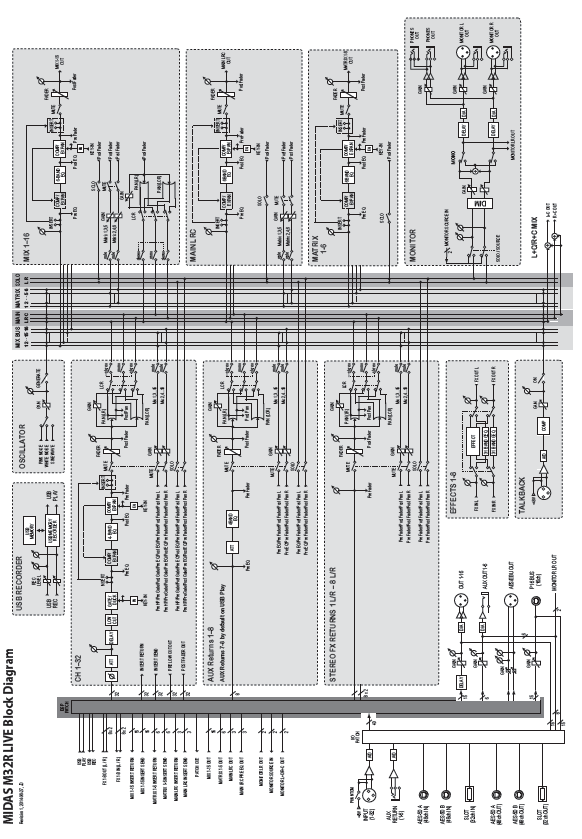
Block Diagram
Technical Specifications
Processing
| Input Processing Channels | 32 Input Channels, 8 Aux Channels, 8 FX Return Channels |
| Output Processing Channels | 8 / 16 |
| 16 aux buses, 6 matrices, main LRC | 100 |
| Internal Effects Engines (True Stereo / Mono) | 8 / 16 |
| Internal Show Automation (structured Cues / Snippets) | 500 / 100 |
| Internal Total Recall Scenes (incl. Preamplifiers and Faders) | 100 |
| Signal Processing | 40-Bit Floating Point |
| A/D Conversion (8-channel, 96 kHz ready) | 24-Bit, 114 dB Dynamic Range, A-weighted |
| D/A Conversion (stereo, 96 kHz ready) | 24-Bit, 120 dB Dynamic Range, A-weighted |
| I/O Latency (Console Input to Output) | 0.8 ms |
| Network Latency (Stage Box In > Console > Stage Box Out) | 1.1 ms |
Connectors
| MIDAS PRO Series Microphone Preamplifier (XLR) | 16 |
| Talkback Microphone Input (XLR) | 1 |
| RCA Inputs / Outputs | 2 / 2 |
| XLR Outputs | 8 |
| Monitoring Outputs (XLR / ¼” TRS Balanced) | 2/2 |
| Aux Inputs/Outputs (¼” TRS Balanced) | 6 / 6 |
| Phones Output (¼” TRS) | 1 (Stereo) |
| AES50 Ports (KLARK TEKNIK SuperMAC) | 2 |
| Expansion Card Interface | 32 Channel Audio Input / Output |
| ULTRANET P-16 Connector (No Power Supplied) | 1 |
| MIDI Inputs / Outputs | 1 / 1 |
| USB Type A (Audio and Data Import / Export) | 1 |
| USB Type B, rear panel, for remote control | 1 |
| Ethernet, RJ45, rear panel, for remote control | 1 |
Mic Input Characteristics
| Design | MIDAS PRO Series |
| THD+N (0 dB gain, 0 dBu output) | < 0.01% unweighted |
| THD+N (+40 dB gain, 0 dBu to +20 dBu output) | < 0.03% unweighted |
| Input Impedance (Unbalanced / Balanced) | 10 kΩ / 10 kΩ |
| Non-Clip Maximum Input Level | +23 dBu |
| Phantom Power (Switchable per Input) | +48 V |
| Equivalent Input Noise @ +45 dB gain (150 Ω source) | -125 dBu 22 Hz-22 kHz, unweighted |
| CMRR @ Unity Gain (Typical) | > 70 dB |
| CMRR @ 40 dB Gain (Typical) | > 90 dB |
Input /Output Characteristics
| Frequency Response @ 48 kHz Sample Rate | 0 dB to -1 dB 20 Hz – 20 kHz |
| Dynamic Range, Analogue In to Analogue Out | 106 dB 22 Hz – 22 kHz, unweighted |
| A/D Dynamic Range, Preamplifier and Converter (Typical) | 109 dB 22 Hz – 22 kHz, unweighted |
| D/A Dynamic Range, Converter and Output (Typical) | 109 dB 22 Hz – 22 kHz, unweighted |
| Crosstalk Rejection @ 1 kHz, Adjacent Channels | 100 dB |
| Output level, XLR Connectors (Nominal / Maximum) | +4 dBu / +21 dBu |
| Output Impedance, XLR Connectors (Unbalanced / Balanced) | 50 Ω / 50 Ω |
| Input impedance, TRS Connectors (Unbalanced / Balanced) | 20 kΩ / 40 kΩ |
| Non-Clip Maximum Input Level, TRS Connectors | +21 dBu |
| Output Level, TRS (Nominal / Maximum) | +4 dBu / +21 dBu |
| Output Impedance, TRS (Unbalanced / Balanced) | 50 Ω / 50 Ω |
| Phones Output Impedance / Maximum output Level | 40 Ω / +21 dBu (Stereo) |
| Residual Noise Level, Out 1-16 XLR Connectors, Unity Gain | -85 dBu 22 Hz-22 kHz, unweighted |
| Residual Noise Level, Out 1-16 XLR Connectors, Muted | -88 dBu 22 Hz-22 kHz, unweighted |
| Residual Noise Level, TRS and Monitor out XLR Connectors | -83 dBu 22 Hz-22 kHz, unweighted |
DN32-LIVE USB Interface
| USB 2.0 high speed, type-B (audio/MIDI interface) | 1 |
| USB input / output channels, duplex | 32, 16, 8, 2 |
| Windows DAW applications (ASIO, WASAPI and WDM audio device interface) | Win 7 32/64-bit, Win10 32/64-bit |
| Mac OSX DAW applications (Intel CPU only, no PPC support, CoreAudio) | Mac OSX 10.6.8**, 10.7.5, 10.8, 10.9, 10.10, 10.11, 10.12 |
DN32-LIVE SD Card Interface
| SD card slots, SD/SDHC | 2 |
| SD/SDHC supported file system | FAT32 |
| SD/SDHC card capacity, each slot | 1 to 32 GB |
| Battery for power blackout protection (optional) | CR123A Lithium cell |
| SD card input / output channels | 32, 16, 8 |
| Sample rates (console clock) | 44.1 kHz / 48 kHz |
| Sample word length | 32 bit PCM |
| File format (uncompressed multi-channel) | WAV 8, 16 or 32 channels |
| Maximum recording time (32 ch, 44.1 kHz, 32-bit on two 32 GB SDHC media) | 200 min |
| Typical performance recording or playback | 32 channels on class 10 media, 8 or 16 channels on class 6 media |
Display
| Main Screen | 5″ TFT LCD, 800 x 480 Resolution, 262k Colours |
| Channel LCD Screen | 128 x 64 LCD with RGB Colour Backlight |
| Main Meter | 18 Segment (-45 dB to Clip) |
Physical
| Standard Operating Temperature Range | 5°C – 40°C (41°F – 104°F) |
| Dimensions | 478 x 617 x 208 mm (18.8 x 24.3 x 8.2″) |
| Weight | 14.3 kg (31.5 lbs) |
![]()
References
[xyz-ips snippet=”download-snippet”]