Middleby Marshall PS540-Series Ovens PS540E
User Manual
WARNINGFOR YOUR SAFETY, DO NOT STORE OR USE GASOLINE OR OTHER FLAMMABLE VAPORS AND LIQUIDS IN THE VICINITY OF THIS OR ANY OTHER APPLIANCE.
WARNINGImproper installation, adjustment, alteration, service, or maintenance can cause property damage, injury, or death. Read the installation, operation, and maintenance instructions thoroughly before installing or servicing this equipment.
NOTICEThe warranty is NOT VALID unless the oven is installed, started, and demonstrated under the supervision of a factory-authorized installer.
NOTICEContact your authorized Service Agency to perform maintenance and repairs. A Service Agency Directory is supplied with your oven.
NOTICEUsing any parts other than genuine Middleby Marshall factory-manufactured parts relieves the manufacturer of all warranty and liability.
NOTICEMiddleby Marshall (Manufacturer) reserves the right to change specifications at any time.
KEEP THIS MANUAL IN A VISIBLE LOCATION NEAR THE OVEN FOR FUTURE REFERENCE.
Model No._______ Serial No._______ Installation Date_______
MIDDLEBY MARSHALL
NO QUIBBLE LIMITED WARRANTY (U.S.A. ONLY)
MIDDLEBY MARSHALL, HEREINAFTER REFERRED TO AS “THE SELLER”, WARRANTS EQUIPMENT MANUFACTURED BY IT TO BE FREE FROM DEFECTS IN MATERIAL AND WORKMANSHIP FOR WHICH IT IS RESPONSIBLE. THE SELLER’S OBLIGATION UNDER THIS WARRANTY SHALL BE LIMITED TO REPLACING OR REPAIRING, AT SELLER’S OPTION, WITHOUT CHARGE, ANY PART FOUND TO BE DEFECTIVE AND ANY LABOR AND MATERIAL EXPENSE INCURRED BY SELLER IN REPAIRING OR REPLACING SUCH PART. SUCH WARRANTY SHALL BE LIMITED TO THE ORIGINAL PURCHASER ONLY AND SHALL BE EFFECTIVE FOR A PERIOD OF ONE YEAR FROM DATE OF ORIGINAL INSTALLATION, OR 18 MONTHS FROM DATE OF PURCHASE, WHICHEVER IS EARLIER, PROVIDED THAT TERMS OF PAYMENT HAVE BEEN FULLY MET.
This warranty is valid only if the equipment is installed, started, and demonstrated under the supervision of a factory-authorized installer.
Normal maintenance functions, including lubrication, cleaning, or customer abuse, are not covered by this no quibble warranty .
Seller shall be responsible only for repairs or replacements of defective parts performed by Seller’s authorized service personnel. Authorized service agencies are located in principal cities throughout the contiguous United States, Alaska, and Hawaii. This warranty is valid in the 50 United States and is void elsewhere unless the product is purchased through Middleby International with warranty included. The foregoing warranty is exclusive and in lieu of all other warranties, expressed or implied. There are no implied warranties of merchantability or of fitness for a particular purpose.
The foregoing shall be Seller’s sole and exclusive obligation and Buyer’s sole and exclusive remedy for any action, including breach of contract or negligence. In no event shall Seller be liable for a sum in excess of the purchase price of the item. Seller shall not be liable for any prospective or lost profits of Buyer.
This warranty is effective on Middleby Marshall equipment sold on, or after, February 15, 1995.
MIDDLEBY MARSHALL INC. OVEN LIMITED WARRANTY (Non U.S.A.)
The Seller warrants equipment manufactured by it to be free from defects in material and workmanship for which it is responsible. The Seller’s obligation under this warranty shall be limited to replacing or repairing, at Seller’s option, without charge, F.O.B. Seller’s factory, any part found to be defective and any labor and material expense incurred by Seller in repairing or replacing such part. Such warranty is limited to a period of one year from date of original installation or 15 months from date of shipment from Seller’s factory, whichever is earlier, provided that terms of payment have been fully met. All labor shall be performed during regular working hours. Overtime premium will be charged to the Buyer.
This warranty is not valid unless equipment is installed, started, and demonstrated under the supervision of a factory-authorized installer.
Normal maintenance functions, including lubrication, adjustment of airflow, thermostats, door mechanisms, microswitches, burners and pilot burners, and replacement of light bulbs, fuses and indicating lights, are not covered by warranty.
Any repairs or replacements of defective parts shall be performed by Seller’s authorized service personnel. Seller shall not be responsible for any costs incurred if the work is performed by other than Seller’s authorized service personnel.
When returning any part under warranty, the part must be intact and complete, without evidence of misuse or abuse, freight prepaid.
Seller shall not be liable for consequential damages of any kind which occur during the course of installation of equipment, or which result from the use or misuse by Buyer, its employees or others of the equipment supplied hereunder, and Buyer’s sole and exclusive remedy against Seller for any breach of the foregoing warranty or otherwise shall be for the repair or replacement of the equipment or parts thereof affected by such breach.
The foregoing warranty shall be valid and binding upon Seller if and only if Buyer loads, operates and maintains the equipment supplied hereunder in accordance with the instruction manual provided to Buyer. Seller does not guarantee the process of manufacture by Buyer or the quality of product to be produced by the equipment supplied hereunder and Seller shall not be liable for any prospective or lost profits of Buyer.
THE FOREGOING WARRANTY IS EXCLUSIVE AND IN LIEU OF ALL OTHER EXPRESS AND IMPLIED WARRANTIES WHAT SO EVER. SPECIFICALLY THERE ARE NO IMPLIED WARRANTIES OF MERCHANTABILITY OR OF FITNESS FOR A PARTICULAR PURPOSE.
The foregoing shall be Seller’s sole and exclusive obligation and Buyer’s sole and exclusive remedy for any action, whether in breach of contract or negligence. In no event shall seller be liable for a sum in excess of the purchase price of the item.
SECTION 1 DESCRIPTION
MODEL IDENTIFICATION
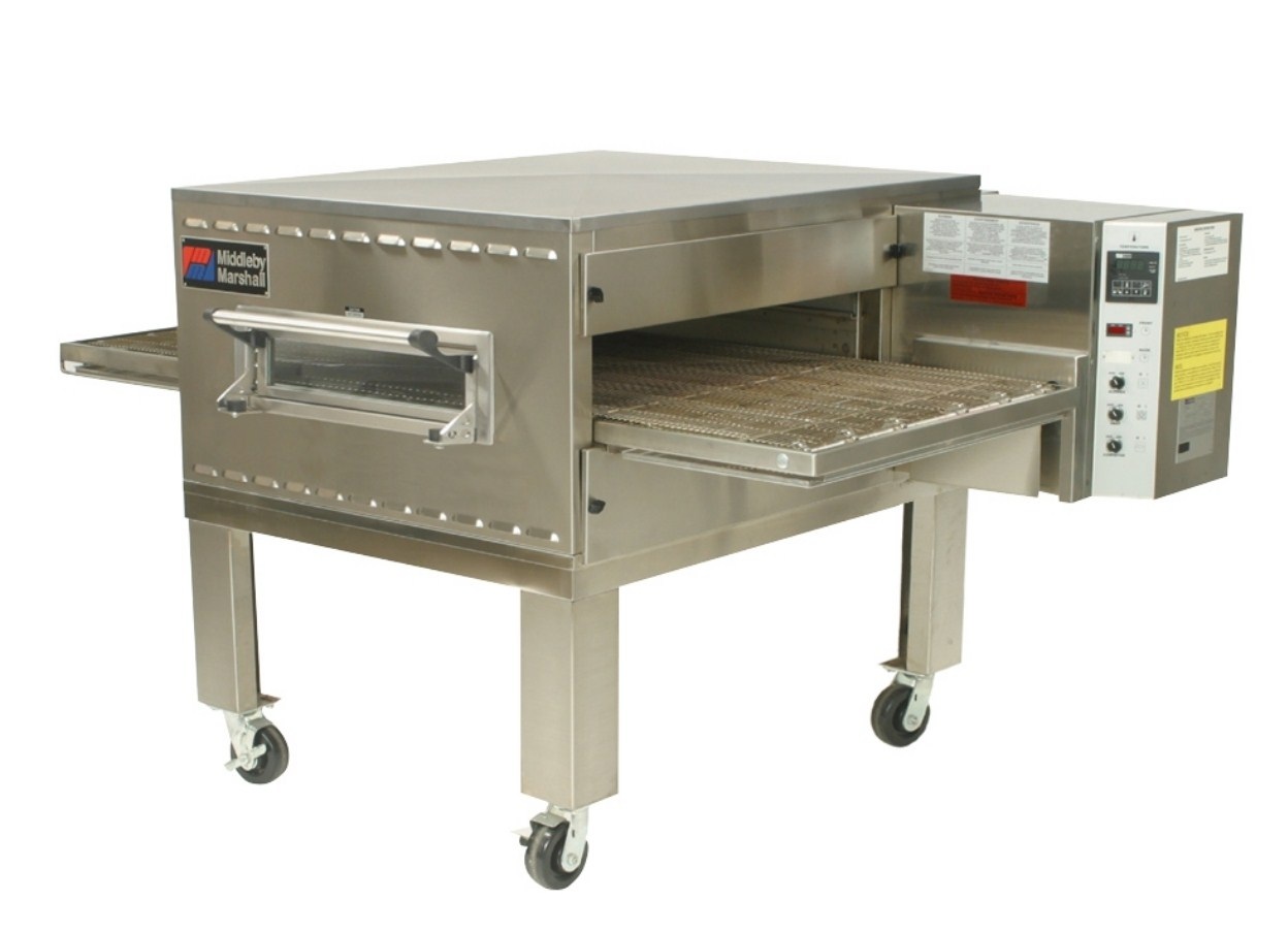
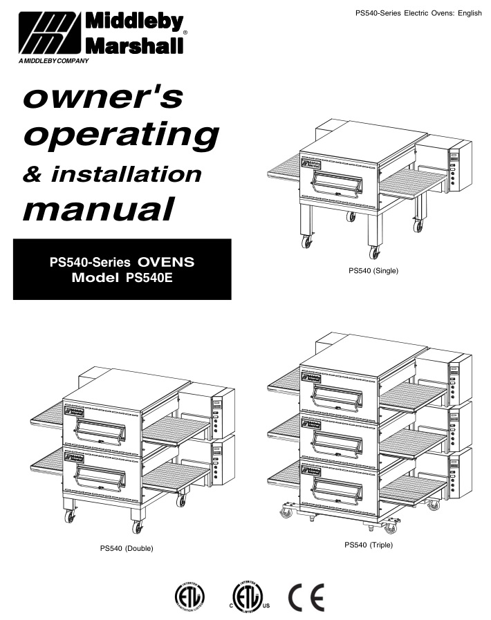
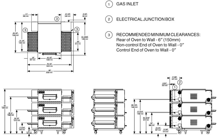
The Middleby Marshall PS540-Series may be used either as a single oven or stacked for use as double or triple ovens. The major difference between the oven models in this series is the width of the conveyor.
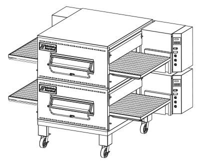
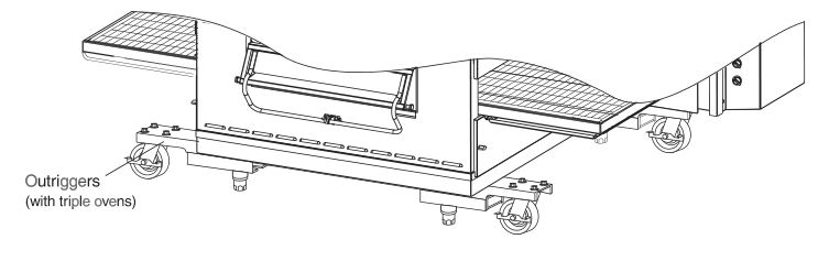
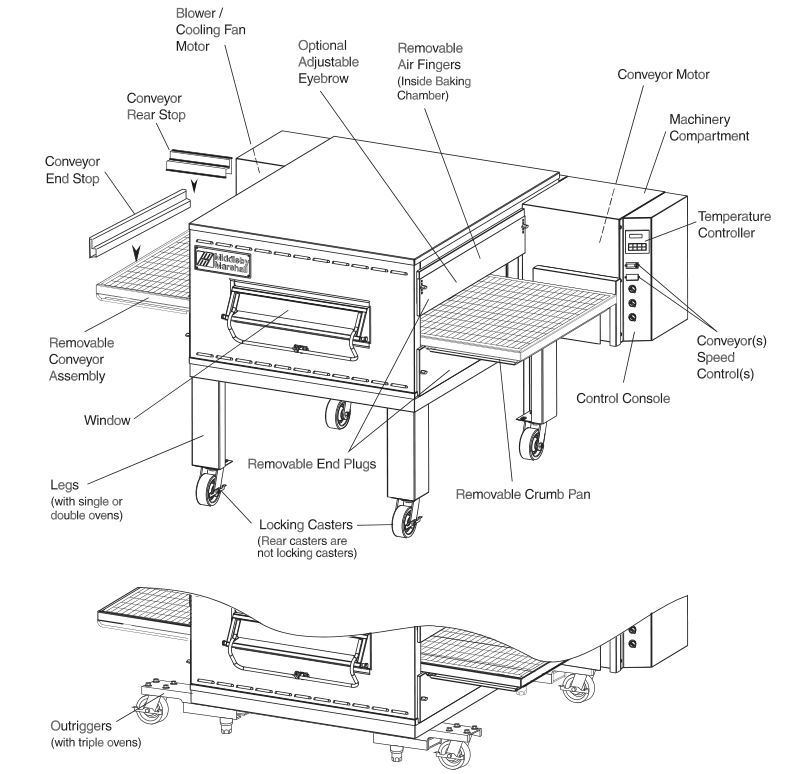
A single PS540-Series Oven (Figure 1-1) is mounted on a base pad with legs and casters. A double oven (Figure 1-2) consists of two, stacked, single ovens. A triple oven (Figure 1-3) consists of three stacked single ovens. The lower oven is mounted on a base pad with short legs and casters.
On a double or triple oven, the ovens operate completely independent. All ovens use identical controls and components. One oven can be cleaned or serviced, while the others are operating.


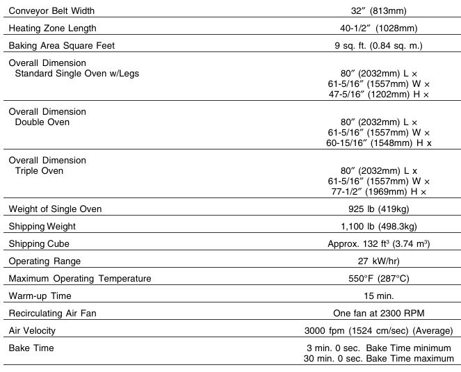
PS540 SERIES OVEN SPECIFICATIONS
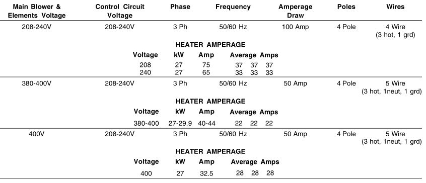
SERIES PS540 ELECTRICAL SPECIFICATIONS
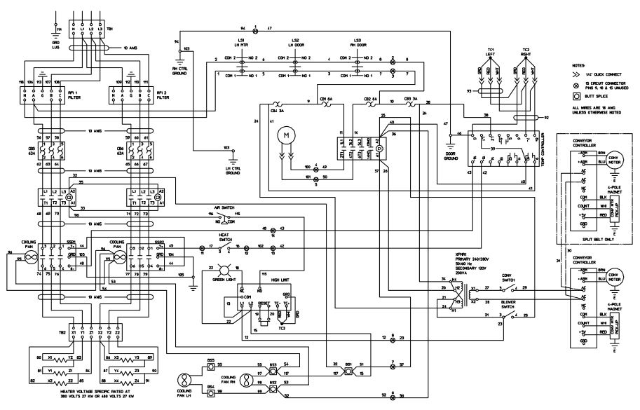
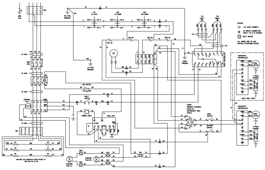
NOTEWiring Diagrams are contained in Section 7 of this Manual and are also located inside the oven at the bottom of the Control Panel
This Manual Must Be Kept For Future Reference
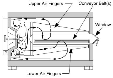
PRINCIPLE OF AIR FLOW
The fan-style blower draws air into the oven plenum where it is heated. The blower then pushes the hot air through the air fingers into the baking chamber. Each air finger contains an inner plate and outer plate that form the hot air into jets, distributing it across a conveyor belt on which the food product rides. Air is then pulled back into the blower and the process continues. The curving, black arrows of Figure 1-4 show this air flow.
Heat Transfer and How It Works
- Heat constantly moves from a warm object to a cold object. Heat moves using three different paths: Conduction; Radiation; and Convection.Conduction: This path utilizes surface-to-surface contact. The pizza dough in contact with the pan is a goodexample of conduction.Radiation: This path has to do with objects radiating heat. Dark objects absorb heat whereas light or shiny objects reflect more heat. This is the reason that the inside of a PS540-Series Oven is light in color: To reflect more heat back onto the food product.Convection: This path has to do with moving a volume of air. It explains why hot air rises and cooler air replaces hot air. An industrial application of this principle is to incorporate a fan to force the hot air movement, which in turn increases the heat transfer to the food product.Each PS540-Series Oven has a large fan-style blower to move the hot air through the air fingers and onto the product to cook/bake the food product most efficiently.
- Temperature is the intensity of heat at the point where it is sensed. As discussed above, heat flows by conduction, radiation and convection. The speed at which the heat flows is determined by the temperature difference between the oven and the food product. The larger the difference, the faster the heat flows to the item that is being baked.
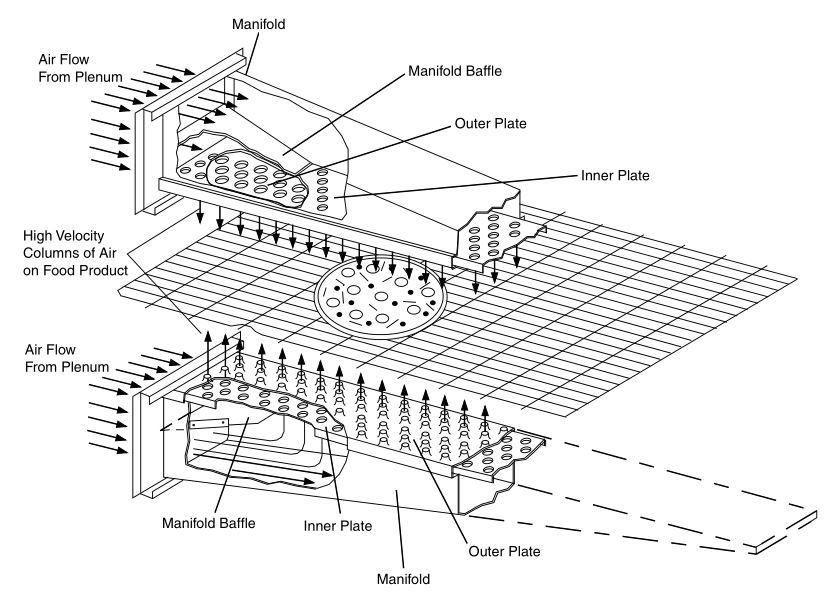
Air Fingers
The PS540-Series Ovens are conveyorized ovens that employ vertical jets of hot air streaming from air fingers (Figure 1-5) to give uniform, intense heating. The vertical streams of hot air provide an exceptional heat transfer rate and generally bake faster and at lower temperatures than convection hot air or infrared heating ovens.
A PS540-Series Oven can accommodate up to four bottom air fingers and four top air fingers. Some PS540-Series ovens used to bake pizza have four bottom fingers and two top fingers. For special product baking requirements, a number of other styles of fingers and finger arrangements are available from the factory.
NOTE: Some customers have a predetermined finger arrangement. If you have any questions pertaining to the finger arrangement, please call the factory.
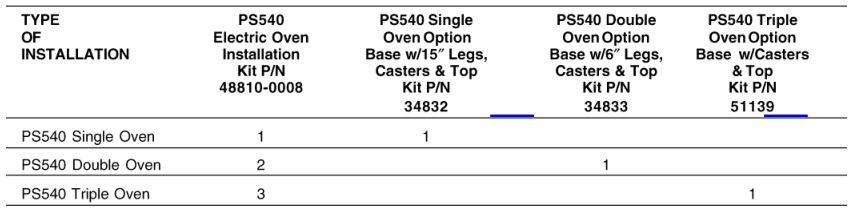
COMPONENT FUNCTION (Figure 1-6)

Conveyor Motor and Conveyor Belt
The conveyor belt is driven by a variable-speed electric motor (Figure 1-7) operating through a gear reducer. The motor speed is controlled by a digital control. The stainless-steel wire belt can travel in either direction at variable rates ranging from 3 minutes to 30 minutes; this is the time that a product can take to pass through the oven.
Blower Fan
The blower fan is located at the rear of the oven. This blower forces heated air through the air fingers. The BLOWER switch must be set to “ON” or “I” for oven warmup and baking.
Electric Heaters
There is one heater element mounted on the inside of the rear panel. The element is connected to an electrical control which is energized by the temperature controller.
If the pilot flame does not light or a loss of flame occurs, the main gas valve closes.
The main burner gas is extinguished when the HEAT switch is set to “OFF” or “O”.
Window
A window on the front of the oven permits viewing the items being baked and provides access to the oven for items that do not require full baking time, such as sandwiches, cookies, small items, or cheese-melting processes.
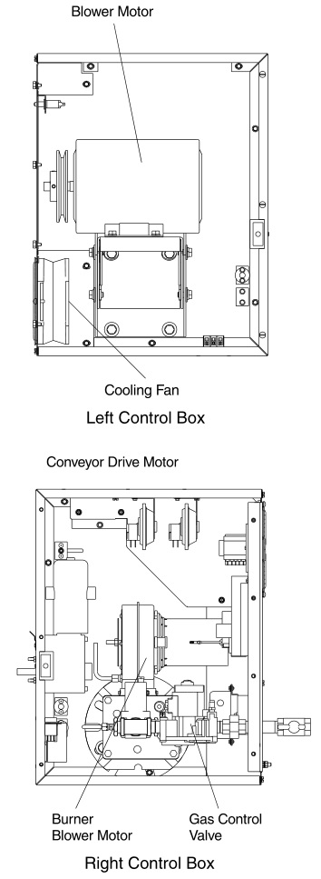
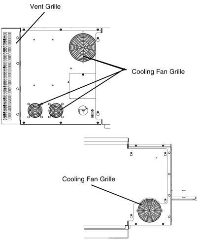
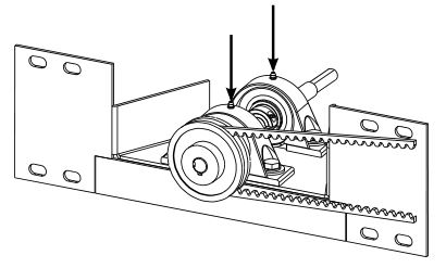
Cooling Fan — See Figure 1-8
The cooling fans are located in the back of the oven. These cooling fans draw air through its grille, blowing it through the blower motor compartment and the control compartment into the oven top and exhausted out the front louvers.

Air Fingers and Blank Plates – See Figure 1-9
Air Fingers
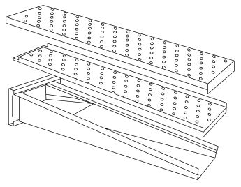
An Air Finger Assembly is made up of three parts:
- Outer Plate – The Outer Plate is the removable covering with tapered holes, which direct the air stream onto the product being baked.
- Inner Plate -The perforated Inner Plate is vital in forming the unique air jets. It must be assembled into the manifold with its holes aligned with the holes of the outer plate.
- Manifold – The Manifold is the assembly which slides on tracks into the oven plenum.
Blank Plates
- Blank Plates– The Blank Plates are available to install on the plenum where an air finger is not required.
SECTION 2 INSTALLATION
NOTE: The oven, when installed, must be electrically grounded in accordance with local codes, or in the absence of local codes, with the National Electrical Code (NEC), or ANSI/NFPA70.
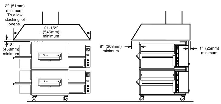
NOTEThere must be adequate clearance between the oven and any adjacent combustible construction. Clearance must also be provided for servicing and for operation.
CAUTIONIt is required that the oven be placed under a ventilation hood for adequate air supply and ventilation.
CAUTIONDo not obstruct the flow of combustion and ventilation air to and from your oven. Do not obstruct the ventilation holes in the Control Panel.
CAUTIONOn ovens with the Machinery Drive Compartment located at the right end, a minimum clearance of 0″ to a left side wall, 18″ to a right side wall and 6″ from a back wall to air openings at the rear of the oven must be maintained. On ovens with the machinery/drive compartment located at the left end, a minimum clearance of 0″ to a right side wall, 18″ to a left side wall and 6″ from a back wall to air openings at the rear of the oven must be maintained.
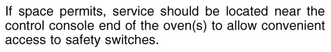
For servicing and cleaning, a minimum of 18″ clearance from all walls is recommended.
UNLOADING
Your Middleby Marshall PS540-Series Oven is shipped partially assembled. It will arrive in a carton on a crate.Carton size for a PS540-Series Oven is:
84″ (2134mm) Long ×58″ (1473mm) Wide ×44″ (1118mm) High ×
The crate and carton must be examined before signing the Bill of Lading. Report any visible damage to the transport company, and check for the proper number of crates. If apparent damage is found, make arrangements to file a claim against the carrier. Surface Interstate Commerce Regulations (U.S.A.) require that the claim must be initiated by the consignee within 10 days from the date that the shipment is received.
A Pre-installation Procedures Manual (MM P/N 88910-0009) is attached to the exterior wall of the carton. This manual contains detailed instructions on unpacking and moving the oven(s) to the operating site. When the transport company notifies you of an impending delivery, arrange to have a forklift at your facility to unload the carton(s).
Instructions for stacking the ovens is continued in a separate manual used by Middleby Marshall Authorized Installers.
If you have a door wider than the carton, simply move the carton into your facility and arrange an appointment with your Middleby Marshall Authorized Installer.
If your door is narrower than the carton, then the oven will have to be unpacked. Follow the directions shown in the Pre-Installation Procedures Manual.
PS540 OVEN INSTALLATION REQUIRED KITS AND EQUIPMENT
PARTS LIST FOR SERIES PS540 ELECTRIC OVEN INSTALLATION KIT P/N 48810-0008(Two required for double oven)(Three required for triple oven)
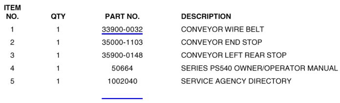

PARTS LIST FOR PS540 SERIES SINGLE OVEN OPTION – BASE w/15″ ″ ″ LEGS & TOP P/N 34832
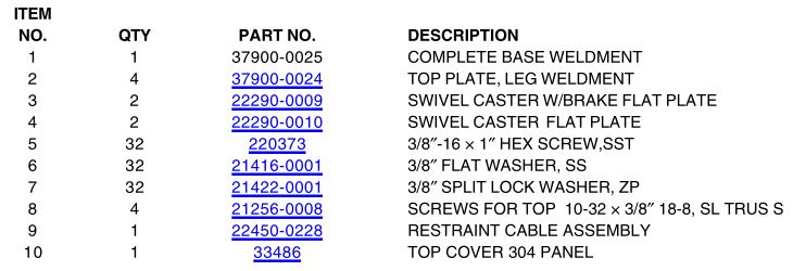
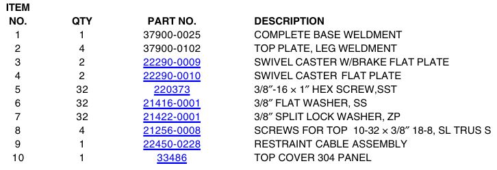
PARTS LIST FOR PS540 SERIES DOUBLE OVEN OPTION – BASE w/6″ LEGS, CASTERS & TOP P/N 34833
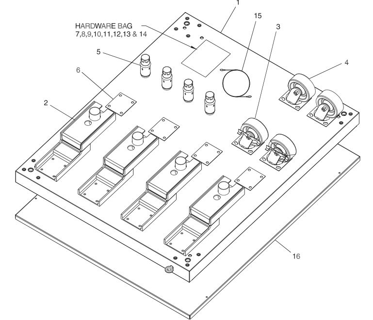
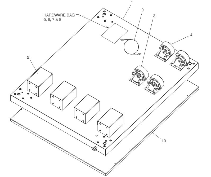
PARTS LIST FOR PS540 SERIES TRIPLE OVEN OPTION – BASE w/CASTERS & TOP P/N 51139
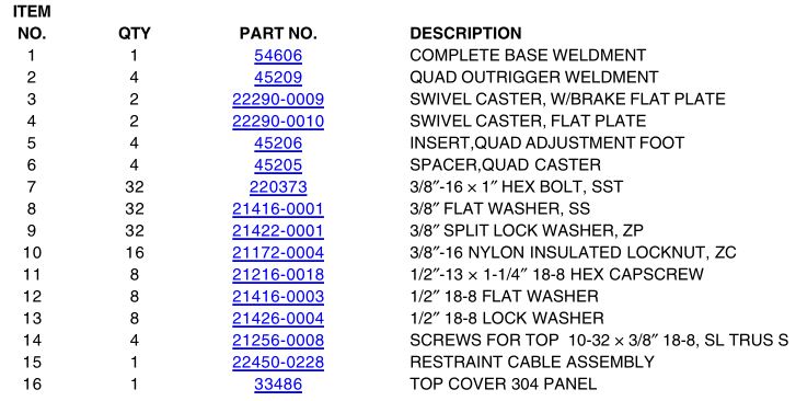

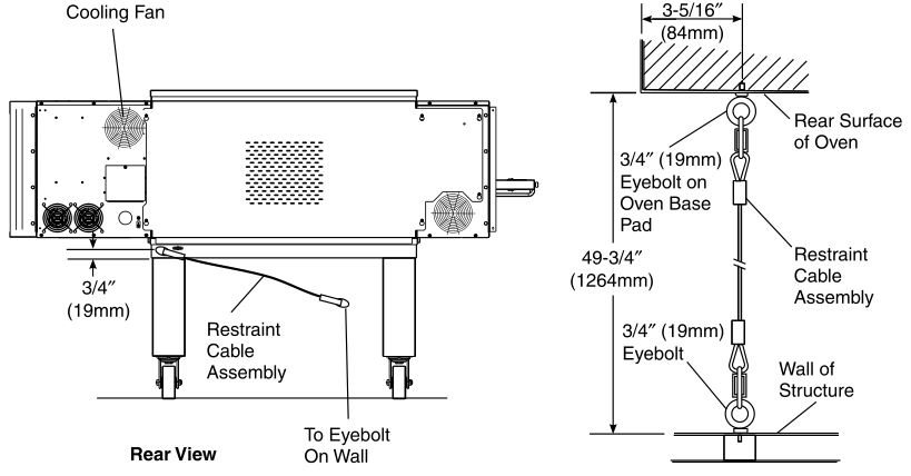
RESTRAINT CABLE INSTALLATION
Install the restraint cable assembly on the oven, as shown in Figure 2-6.
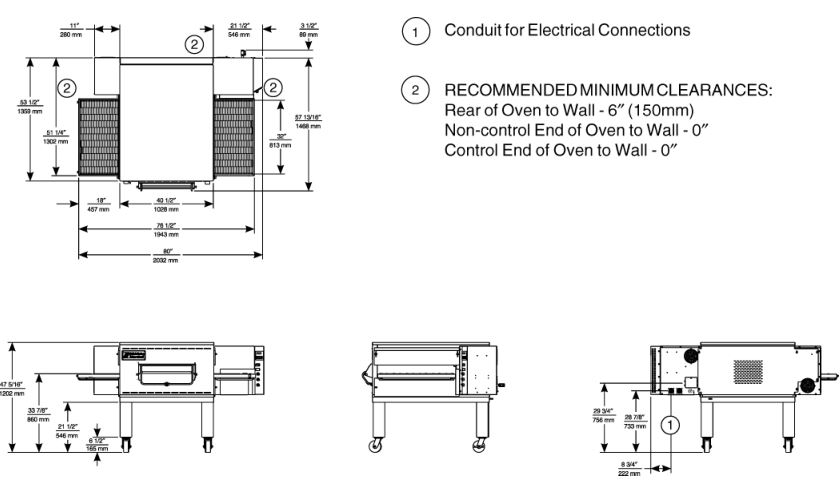
UTILITY ROUGH-IN DIMENSIONS AND POSITIONING FOR PS540-SERIES OVENS
WARNINGDO NOT USE CONDUIT OR GAS LINE FOR GROUND CONNECTION.
CAUTIONIT IS REQUIRED THAT THE OVEN BE PLACED UNDER A VENTILATION HOOD FOR ADEQUATE AIR SUPPLY AND VENTILATION.
ELECTRIC AND GAS SUPPLY TO BE PROVIDED BY CUSTOMER
CIRCUIT BREAKER
Separate circuit breaker with lockout/tagout electrical shutoff for each oven. Wire each oven separately.
100 Amp circuit breaker for 200-240V, or 50 Amp circuit breaker for 380-480V.
ELECTRICAL SPECIFICATIONS
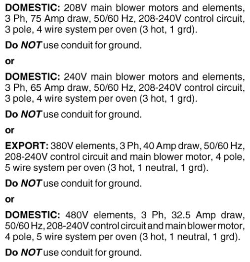

Electrical Rating
27 kw/hr
Supply Wire
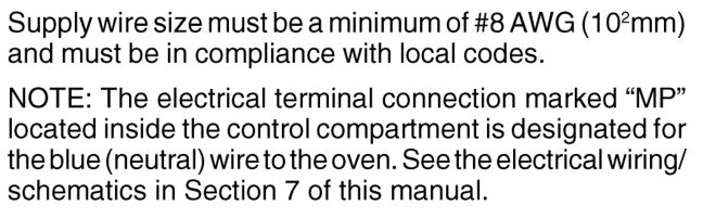
Suggested
VENTILATION GUIDELINES
A mechanically driven ventilation system is required for the PS540 Series Middleby Marshall conveyorized electric ovens. The minimum hood canopy dimensions are outlined below.
Local codes and conditions vary greatly from one area to another and must be complied with. Following are the suggested requirements for good ventilation. Please remember these are recommendations or guidelines, you may have a special condition or problem that will require the services of a ventilation engineer or specialist. Proper ventilation is the oven owner’s responsibility. Improper ventilation can inhibit oven performance. It is recommended that the ventilation and duct work be checked out every three months. Grease filters in the intake of the hood may be required by local codes.
VENTILATION HOOD
The rate of air flow exhausted through the ventilation system is generally between 1400 and 2500 cu. ft./min. (40 and 70 m 3 /min), but may vary depending on the oven configuration and hood design. To avoid a negative pressure condition in the kitchen area, return air must be brought back to replenish the air that was exhausted. A negative pressure in the kitchen can cause heat related problems to the oven components as if there were no ventilation at all. The best method of supplying return air is through the heating, ventilation and air conditioning system. Through they system, the air can be temperaturecontrolled for summer and winter. Return air can be brought in directly from outside the building, but detrimental affects can result from either extreme seasonal hot and cold temperature from the outdoors.
NOTE: Return air from fan driven system within the hood must not blow at opening of bake chamber or poor oven baking performance will result.
ELECTRICAL CONNECTION INFORMATION FOR PS540-SERIES OVENS.
WARNINGAuthorized supplier personnel normally accomplish the connections for the ventilation system, electric supply, and gas supply, as arranged by the customer. Following these connections, the factory-authorized installer can perform the initial startup of the oven.
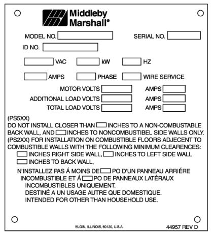
Check the oven data plate (Figure 2-11) before making any electric supply connections. Electric supply connections must agree with data on the oven data plate.
NOTE: The electric supply installation must satisfy the requirements of the appropriate statutory authority, such as the National Electrical Code (NEC), ANSI/NFPA70, (U.S.A.); the Canadian Electrical Code, CSA C22.2; the Australian Code AG601; or other applicable regulations.
A fused disconnect switch or a main circuit breaker (customer furnished) MUST be installed in the electric supply line for each oven; it is recommended that this switch/ circuit breaker have lockout/tagout capability. The electric supply connection must meet all national and local electrical code requirements. Copper is the recommended material for the electrical supply conductors.
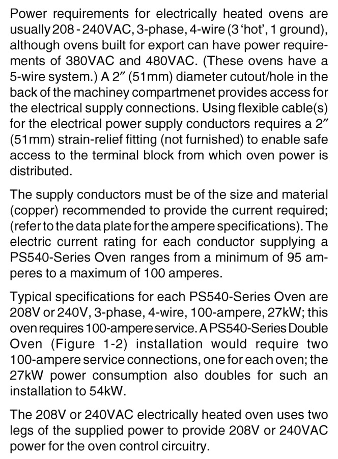
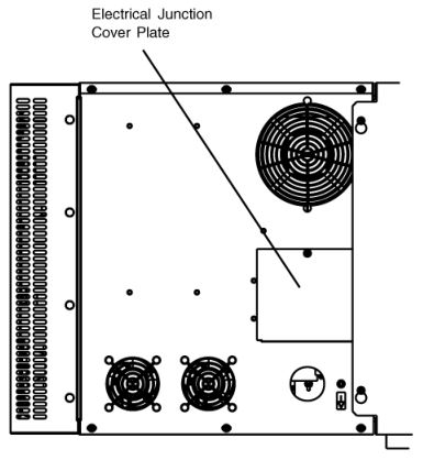
Electric Supply For Electrically Heated Ovens
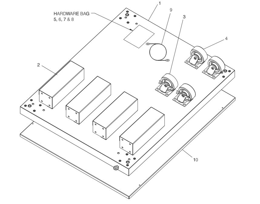
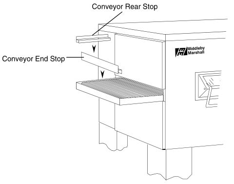
CONVEYOR REAR STOP AND END STOP INSTALLATION
Locate the conveyor rear stop and end stop in the installation kit. Install the rear stop and end stop at the exit end of the oven. See Figure 2-13.
SECTION 3 OPERATION
CONTROL FUNCTIONS
WARNINGA possibility of injury from rotating parts and electric shock exists in this oven. Never disassemble or clean the oven with the BLOWER switch or any other oven control turned “ON” or “I”. Turn “OFF” or “O” and lockout or tagout all electric power to the oven before attempting to clean or service this oven.
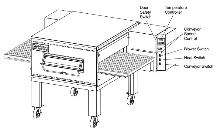
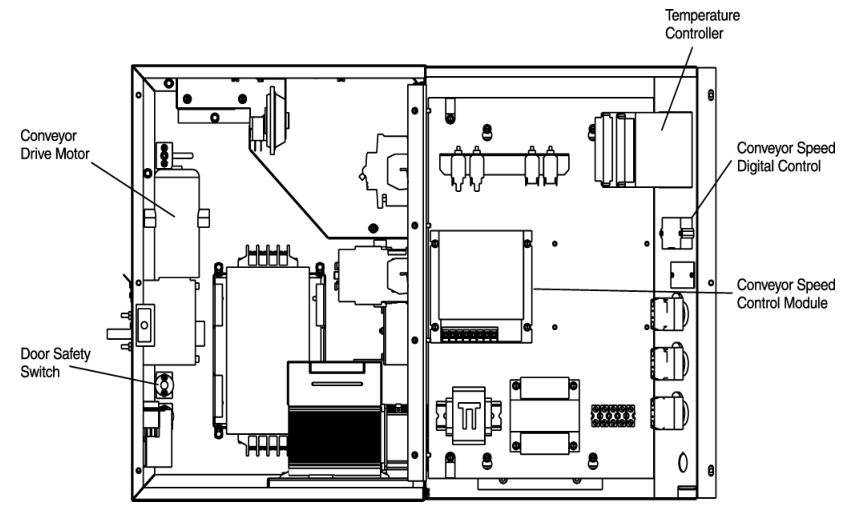
COMPONENT INFORMATION AND LOCATION (Figures 3-1 and 3-2)
Door Safety Switch
The Door Safety Switch is located at the lower left side of control panel opening. Opening the control panel door permits this switch to open, disconnecting power to all electrical controls.
CAUTIONDo NOT touch the wires going to this safety switch. Current is always present.
Blower Switch
The blower switch has two positions. The switch must be “ON” or “I” for the burner to come on and permit the oven to warm up. The fan circulates the air throughout the oven and must stay on during baking and during the cool down cycle above 200°F (93°C) to prevent blower bearing damage. To protect the blower motor and bearings a thermostatic override is built into the oven. If the temperature inside the oven is over 180°F (82°C) the main blower will continue to run after the blower switch is turned to the “OFF” or “O” position.
An air pressure switch monitors the air flow from the blower, acting as a safety interlock for the burner. The burner cannot light, if the air switch does not sense air flow off the main blower fan.
Heat Switch
Turning the HEAT switch to “ON” or “I” will initially set up the oven purge circuit. After approximately 30 seconds, the burner lights. After the burner is lit, a flame sensor sends a signal to the ignition module to stop the spark. The burner will run unless the flame sensor does not detect a flame or the heat switch is turned to the “OFF” or “O” position.
The HEAT switch is in series with the burner blower motor centrifugal switch, the high-temperature safety switch, and the blower fan air pressure switch. All three safety switches must be closed for gas to flow and the burner to light.
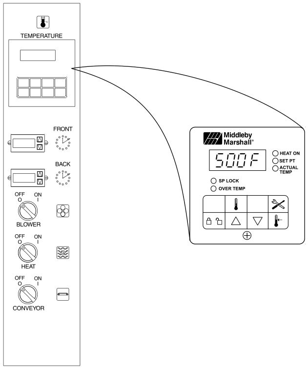
Temperature Controller
The temperature controller is a solid-state, on/off type to maintain the operator-set temperature. The temperature controller continuously monitors the oven temperature and turns on the modulating solenoid valve in a gas-heated oven. The heat is on for the time required to maintain a constant oven temperature.
The temperature controller contains a low-limit switch which allows the oven to cool down to 200°F (93°C) before shutting off the blower. A high-limit indication (ALM 1) will appear on the display if the oven reaches 650°F (343°C).
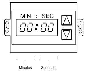
Conveyor
The on-off switch for the conveyor motor is on the control panel. Also on the control panel is the digital conveyor speed control. The digital control can be adjusted from 3 min. to 30 min. bake time (conveyor speed). Refer to Figure 3-3.
Conveyor speed is measured by the amount of time it takes for an item to go through the bake chamber of the oven.
MEASURING CONVEYOR SPEED.See Figures 3-4 and 3-5.To check conveyor speed, place a product item at the entrance end of baking chamber as shown. Time how long it takes for the leading edge of the item to go from the entrance end of the baking chamber to the exit end. This should be the conveyor speed shown on the conveyor speed digital control.
NOTE: In Figures 3-4 and 3-5, the oven shown is with the conveyor running right to left.
WARNINGPossibility of injury from rotating parts and electrical shock exist in this oven. Never disassemble or clean the oven with the blower switch or any other part of the oven turned “ON” or “I”. Turn “OFF” or “O” and lockout or tagout all electrical power to the oven before attempting to clean or service this oven.


WARNINGOVEN MUST BE KEPT CLEAR OF COMBUSTIBLES AT ALL TIMES.
STEP-BY-STEP OPERATION
Control Panel (On split belt ovens, two conveyor speed controls are mounted on the control panel.)
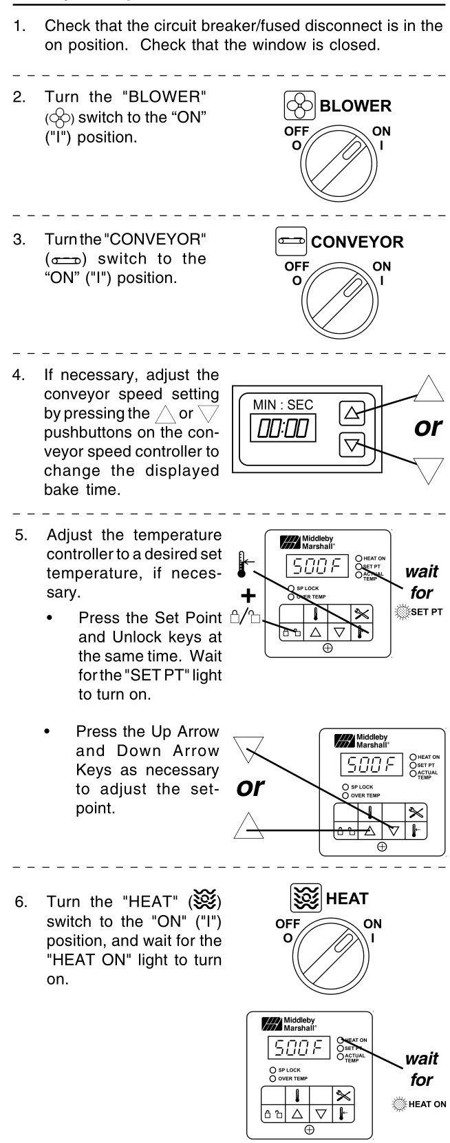
Startup Procedures
Daily Startup
- Turn the BLOWER switch (Figure 3-6) to the “ON” or “I” position. This starts the main blower fan and the cooling fan. The blower circulates air through the air fingers and must stay on during the cooking or baking process.
- Check to see if the cooling fan (see Figure 1-8) is operating when the blower switch (see Figure 3-6) is turned “ON” or “I”. The cooling fans cool the control components and burner blower motor. The cooling fan, located at the rear of the electrical control cabinet blows air into and through the cabinet. Air is exhausted through the front of the cabinet and also out the front of the oven. Refer to Daily Maintenance Section for fan intake checking procedure.IMPORTANT NOTEThe cooling fan operates when the BLOWER switch is turned “ON” or “I”. It must operate to keep the control console below 140°F (60°C).
- Turn the CONVEYOR switch (Figure 3-6) to the “ON” or “I” position. This starts the conveyor belt moving through the oven. Set the conveyor speed for the desired baking time. Refer to the following Procedures E, F and G.
- Set the temperature controller to the desired baking temperature. See section on bake times to determine desired temperature.NOTE: For complete temperature controller operation instructions refer to Step C.
- Turn the HEAT switch (Figure 3-6) to the “ON” or “I” position. This completes a circuit to supply electric power to the electric heating system.
- Close front window.
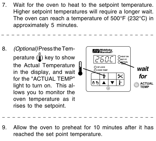
- Oven will reach a baking temperature of 500°F (232°C) in approximately 10 minutes. Allow the oven to cycle for 30 minutes after it has reached desired bake temperature. The oven is now ready for baking.
Power Failure
In case of power failure, turn off all switches; open oven window and remove product. After power has been reestablished follow normal startup procedure.
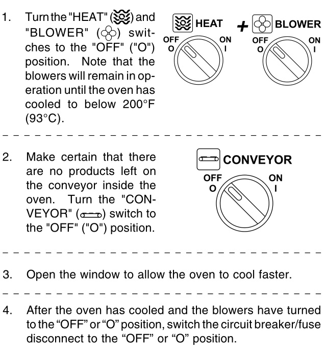
Shutdown Procedure
- Turn the BLOWER and HEAT switches to “OFF” or “O”.NOTE: The blowers will remain on until the oven temperature cools down to 200°F (93°C) at which time they will stop automatically.
- Make certain that there are no products left on the conveyor inside the oven. Turn the CONVEYOR switch to “OFF” or “O”.
- Turn off the main gas supply valve.
- Open the oven window.
NORMAL OPERATION – STEP-BY-STEP
Daily Startup Procedure
DAILY SHUTDOWN PROCEDURE
CAUTIONIn case of power failure, turn all switches to the “OFF” (“O”) position, open the oven window, and remove the product. After the power has been restored, perform the normal startup procedure. IF THE OVEN WAS SWITCHED OFF FOR LESS THAN 5 MINUTES, WAIT FOR AT LEAST FIVE MINUTES BEFORE RE- STARTING THE OVEN.
The burner will not operate and gas will not flow through the burner without electric power. No attempt should be made to operate the oven during a power failure.

QUICK REFERENCE: TROUBLESHOOTING

IF THESE STEPS FAIL TO RESOLVE THE PROBLEM, CONTACT YOUR LOCAL MIDDLEBY MARSHALL AUTHORIZED SERVICE AGENT. A SERVICE AGENCY DIRECTORY IS SUPPLIED WITH YOUR OVEN.
SECTION 4 MAINTENANCE
WARNINGPossibility of injury from rotating parts and electrical shock exist in this oven. Turn off and lockout or tagout electrical supply to oven(s) before attempting to disassemble, clean or service oven(s). Never disassemble or clean the oven with the blower switch or any other part of the oven turned on.
WARNINGBefore performing any maintenance work or cleaning, turn main power switch off.
CAUTIONWhen cleaning do not use any abrasive cleaning materials or water spray, wipe clean only. Never use a water hose or pressurized steam cleaning equipment when cleaning this oven.
NOTICEIf the oven is to be removed from its installed location for servicing, perform the following procedure:
- Switch off the oven and allow it to cool. Do NOT service the oven while it is warm.
- Turn off main circuit breakers and disconnect connector from oven.
- Turn the adjustable legs to put weight on the casters.
- Move oven to desired location for servicing.
- When servicing is complete, move oven to original location.
- Adjust legs to level oven and take weight off casters.
- Connect electrical and gas connectors to oven.
- Turn on main circuit breakers.
- Follow normal startup instructions.
MAINTENANCE – DAILY
Exterior
Everyday you should clean the outside of the oven with a soft cloth and mild detergent.
WARNINGNever use a water hose or pressurized steam cleaning equipment when cleaning the oven.
Cooling Fan
- TWO COOLING FAN GRILLES AT THE REAR OF EACH OVEN CONTROL COMPARTMENT MUST BECLEANED DAILY – Clean grilles with a stiff nylon type brush.
- Check the air intake of the cooling fan daily. The best time to check is right after starting the oven.IMPORTANT NOTEThe cooling fan operates when the blower switch is turned to “ON” (“I”). It must operate to keep the electrical control cabinet below 140°F (60°C).WARNINGIF FAN BLADE IS NOT ROTATING, BROKEN, OR FAN ASSEMBLY IS MISSING FROM MAIN BLOWER MOTOR SHAFT, DO NOT OPERATE OVEN. REPLACE COOLING FAN BLADE BEFORE OPERATING OVEN. Serious damage could be done to the burner blower motor and/or solid-state electrical components if oven isoperated while cooling fan is not running or vent grille is plugged.
- Using a stiff nylon brush clean control compartment vent grille. Hot air from control compartment exits from this grille.
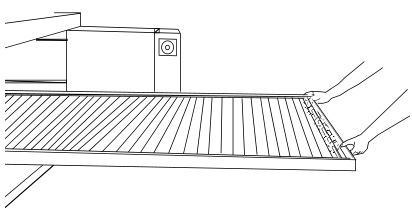
Conveyor Belt (Figure 4-2)
Everyday, just after starting the oven, stand at the unloading end of the conveyor, and with a brush, remove food particles (crumbs, etc.) clinging to the conveyor belt, brushing them into the crumb pan.
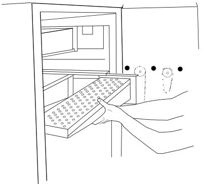
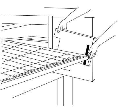
Crumb Pans (Figure 4-2)
Remove and clean the crumb pan at each end of the oven. Each crumb pan can be removed by sliding it out, as shown in Figure 4-2. Reinstall the crumb pans after cleaning.
Window
The window can be cleaned daily while it is in place.

MAINTENANCE – MONTHLY
NOTE: The oven interior may require cleaning more than once a month depending on the volume of baking. To clean the interior, you have to disassemble some parts of the oven.
When cleaning your Series PS540 Oven note the following:
PRECAUTIONS–
- Do not use excessive water or saturation of oven insulation will occur.
- Do not use a caustic oven cleaner or the aluminized finger manifold surfaces will be severely damaged.When cleaning your oven, first remove all heavy debris with a vacuum cleaner. Use a damp cloth for light cleaning.For heavier cleaning of baked on grease and carbon deposits use a non-caustic cleaner that will not react with the aluminized finger manifold surfaces.You can order non-caustic cleaner from your local authorized Middleby Marshall Parts Distributor in the quantities listed below:Part # _________________Quantity27170-0244 _____________ Case of Quarts (6)27170-0246 _____________ Case of Gallons (4)
Removing Conveyor From Oven For Cleaning
- Remove crumb pans as shown in Figure 4-2.
- Remove upper and lower end plugs from each end of oven by removing the two wing screws from each end plug.
- Remove the conveyor end stop and the conveyor rear stop (Figure 4-3).

Figure 4-3 Figure 4-4 Figure 4-5 Figure 4-6 - Remove conveyor drive chain cover as shown.
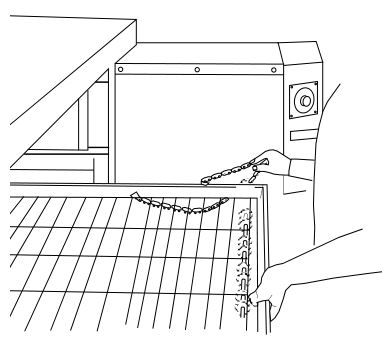
- Remove tension from drive chain by lifting and pushing the conveyor slightly into the oven. Remove drive chain from conveyor drive sprocket as shown.NOTE: The split belt conveyor assembly can only be removed from the drive end of the oven.
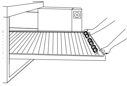
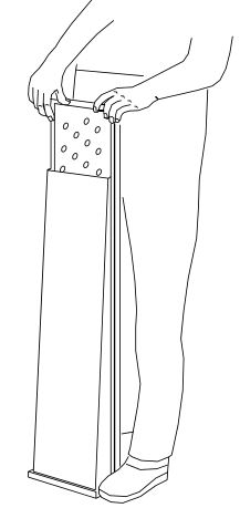
- Begin sliding conveyor out of the oven as shown.
Figure 4-7 - Continue sliding the conveyor completely out of the oven, fold it in half and then place it to the side for cleaning. Be careful not to bump drive sprocket while handling conveyor or damage may result to drive shaft.
Figure 4-8


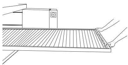
CAUTIONBe careful not to bump the drive sprocket while handling the conveyor, to avoid damaging the drive shaft.
Air Fingers Disassembly For Cleaning
- As the air fingers are removed use a felt pen to mark all parts of the fingers. This includes the finger manifold, innerplate and the outer plate (refer to Figure 1-9). If a blank or choke plate is used, mark that plate also. Fingers are marked in the order shown; as viewed from the front of the oven. (The marks for an upper oven should be preceded with a “U”, example UB1, UT2, etc.)
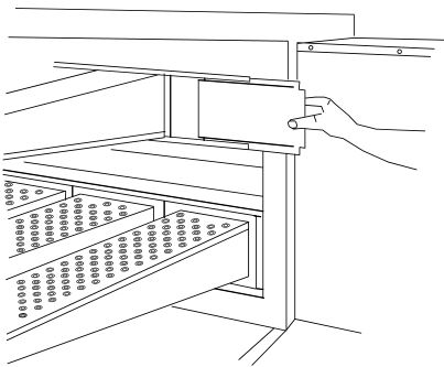
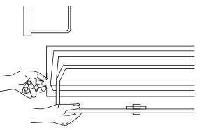
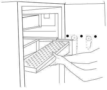
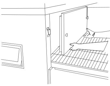
Standard Fingers - Slide blank plates straight out.
Figure 4-9 - Remove air fingers.NOTE: Some oven users require a custom finger arrangement where the quantity of air fingers may vary.You can remove top and bottom fingers and blank plates from each or either end. It is highly recommended that each finger be marked before removing so it is placed in exactly the same position when reassembled (refer to step 1).Remove the air fingers, pull the finger at the back side – pull straight out.
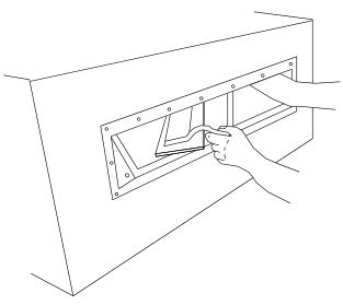
Figure 4-10 - With air fingers out, place them in an upright position to remove the outer plate.
- Gently step o the lip of the finger and pull the outer plate off.
Figure 4-11 - To remove the inner plate, pull the plate out and then up.
- The outer finger plate is stainless and may be cleaned by either soaking in a hot, strong detergent solution or using a caustic cleaner. The conveyor belt can also be cleaned in the same way.
Figure 4-13. Standard Lower Finger Figure 4-14. Standard Upper Finger


Cleaning the Window
The window can be cleaned in place. If it needs a thorough cleaning it may have to be removed.
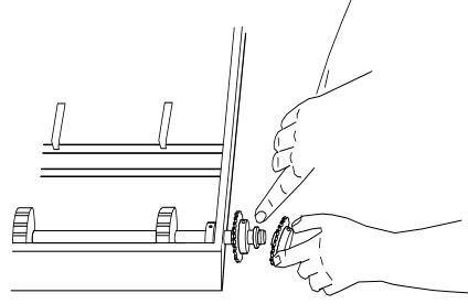
- Remove the window by opening the window and un-screwing the window knobs from each end.
Figure 4-15 - Push the window all the way inside the oven, making sure it is clear of the frame. Now, turn the window sideways while inside the oven and then remove it. This will avoid breaking the window.
Figure 4-16.
Reassembly of Air Fingers
- Air fingers are made up of one inner plate, one outer plate and the finger housing manifold. Be sure to match up the markings (T1, T2, T3, etc.) on all the parts of the air fingers as you are reassembling.
Figure 4-17. - Reassemble the inner plate. Keep your fingers clear so you won’t pinch them. The inner plate of a finger will only go in one way because of its design.
- Replace the outer plate by placing your hands flat on the top of the plate and pushing down. Keep your fingers clear so you won’t pinch them.
Figure 4-18. - Replace the air fingers by pushing in at the back side. Remember to replace them according to the numbers marked on them when they were removed. They must go back in the same way they came out.
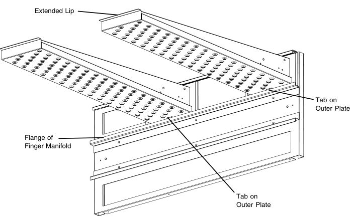
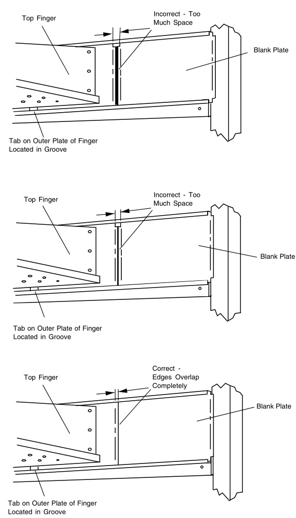
Figure 4-19. IMPORTANT: Only M6 Fingers fit in the bottom row. All M3 and M1 finger cover plates have extended lips at front. This extended lip will not allow these fingers to be installed in the bottom row.IMPORTANT: When inserting fingers the tab on the outer plate must be in the groove as shown in Figure 4-20. There is a blocking tab on the outside of the groove which will prevent inserting the finger in the groove if the outer plate is moved away from the flange of the finger manifold.
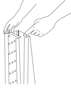
Figure 4-20. - Install fingers and blank plates correctly with edges interlocked and no space between edges.
Figure 4-21.
Reinstall End Plugs
- Reinstall lower end plug. Be sure to tighten two wing screws on the end plug.
- Reinstall conveyor.
- Reinstall upper end plug. Be sure to tighten two wing screws on the end plug.
Conveyor Reassembly Into Oven
- Lift conveyor and position it in oven as shown.NOTE: Conveyor assembly may be inserted into either end of oven. If it is to be installed from the non-drive endof the oven the drive sprocket assembly must be removed as shown in conveyor disassembly section.NOTE: Split belt conveyors can only be inserted from the drive end of the oven.
Figure 4-24. - Reinstall the conveyor rear stop. Reinstall the conveyor end stop.
Figure 4-25.

Checking Conveyor Belt Tension
WARNINGOven conveyor belt must be cool when adjusting belt. Do not adjust belt if HOT.
- With the conveyor assembly in the oven, stand at one end of conveyor and check tension by lifting the conveyor belt at the center of the oven chamber opening. The belt should not lift higher that 3″ to 4″ (75mm to 102mm).
- Adjust conveyor belt tension screws (located on left end of oven) for the 3″ to 4″ (75mm to 102mm) deflection as shown in Figure 4-26. If there is proper tension, proceed to “J. Attaching Drive Chain”. If belt is still too loose, continue to step 3 below.
- If conveyor belt is still not under proper tension, an entire link must be removed. Use the following procedure “H. Conveyor Belt Link Removal” to remove a link. If conveyor belt is under proper tension proceed directly to “J. Attaching Drive Chain”.
Figure 4-26.

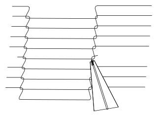
Conveyor Belt Link Removal
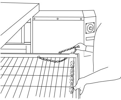
- Using long nose pliers, an entire link can be removed with the conveyor assembly either in or out of the oven. Position master links at end of conveyor as shown in Figure 4-27.
Figure 4-27 - Using long nose pliers, unhook master links at left end of conveyor as shown in Figure 4-28.
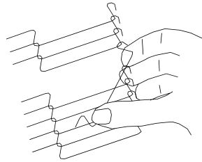
Figure 4-28. - Remove the outside master links on the right and left sides of the conveyor belt as shown in Figure 4-29.
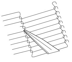
Figure 4-29. - Unhook the link to be removed.
- Pull up on the belt link section and remove. Do not discard the link removed as it may be used for making spare master links.NOTE: If a section of the conveyor belt is being replaced it should be done now. Remove the links that needreplacing and use the section of conveyor belt furnished in your installation kit to replace them.
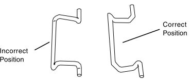
Figure 4-30. NOTE: Before connecting the inside master links, notice that these links have a correct position (Figure 4-31). Thelink at the right is in the correct (horns up) position for inserting into the conveyor belt. The horns facing down are in the incorrect position.
Figure 4-31. - Reconnect the inside master links (Figure 4-32.)
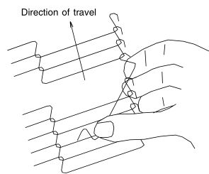
Figure 4-32. NOTE: The outside master links have right and left sides to them. The right edge master link has an open hook facing you as shown in Figure 4-33. This will match up with the outer edges of the conveyor belt. Remember this hook travels backwards on the conveyor.
Figure 4-33. - Reconnect the outside master links.
- Replace all parts removed from the oven.
Figure 4-34.


Replacing Conveyor Belt
If a section of the conveyor belt needs replacing it can be done with the conveyor assembly either in or out of the oven. The section of the conveyor belt furnished with the oven in the installation kit may then be used to replace a section. Follow the preceding procedure “H. Conveyor belt link removal” which outlines the disassembly procedure.
Attaching Drive Chain
- If drive sprocket assembly was removed reassemble it into the conveyor drive shaft. Be sure flat on end of drive shaft aligns with set screw in conveyor shaft collar. Once in place tighten 3/32″ set screw.
- Lift conveyor and install drive chain to conveyor drive sprocket and motor sprocket.
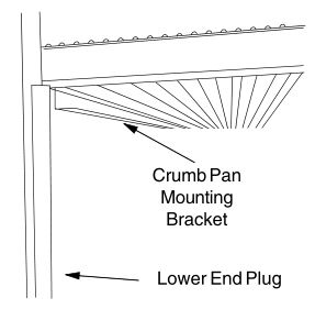
Figure 4-35. - The angle plate located on the underside of the conveyor must be against the lower end plug. This is true on both sides of oven.
Figure 4-36. - Reassemble conveyor drive chain cover and then reassemble the bottom cover to the drive chain cover. Install both upper end plugs.
Figure 4-37.
MAINTENANCE – EVERY 3 MONTHS
WARNINGShut OFF all electrical power and lock/tag out the switch before attempting maintenance work.Shut OFF gas supply to oven.
NOTE: It is recommended that the 3-month maintenance be performed by an authorized Middleby Marshall technician.
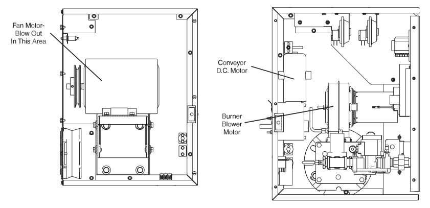
Cleaning the Blower/Fan Motor
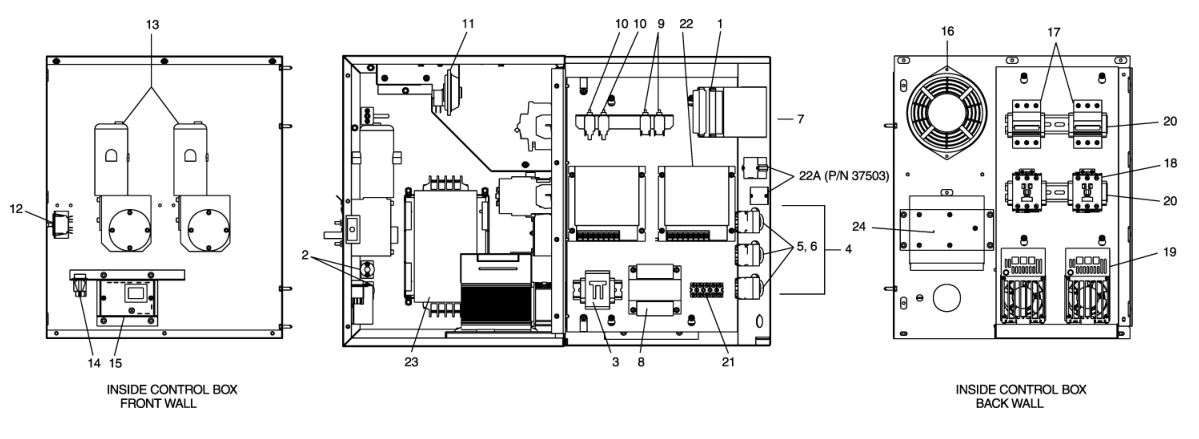
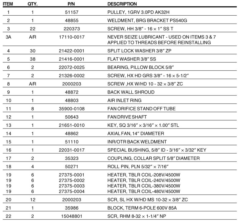
To gain access to the blower/fan motor, open the control cabinet door by removing the three screws. Clean the motor, burner blower motor, the conveyor drive motor and the surrounding area, using either compressed air or CO². Thoroughly blow out the motor compartment and vents inside the motor (Figure 4-38). Failure to do this can cause premature failure of blower fan motor.
CAUTIONNot cleaning the blower/fan motor properly can cause premature failure.
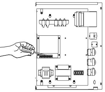
Electrical Terminals
Open the control cabinet door by removing the three screws from the control cabinet door. Tighten all electrical control terminal screws including the electrical contactor terminal screws as shown in Figure 4-39.
Ventilation
Check that the air circulation throughout the oven is not blocked and is working properly.
Checking the Blower/Fan Belt
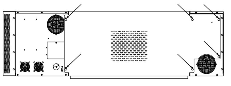
- Check the main blower/fan belt for proper tension and wear. To gain access, loosen the six screws (Figure 4-40) of the rear shroud and lift shroud cover up and off.
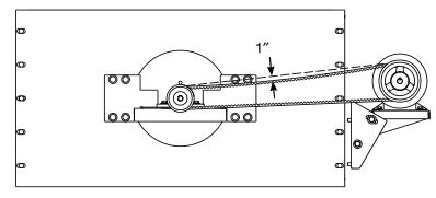
- The fan belt should deflect no less than 1″ (25mm) at the center (Figure 4-41) and have no cracks or excessive wear.
Figure 4-40. CAUTIONOvertightening the belt will cause premature bearing failure and possible vibration problems. A spare belt is located inside the control compartment on the rear wall.
- When replacing the belt, loosen the tension adjustment bolts (Figure 4-42) on the motor mounting bracket. Next, pull back on the motor. Retighten adjustment bolts. Do not overtighten because the fan bearings may be damaged.
Figure 4-41. Figure 4-42.
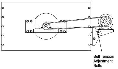
Blower Fan Shaft Bearing Lubrication
CAUTIONOver-greasing damages the bearing seals and accelerates grease loss, which shortens bearing life. Wipe off any excess grease on and around the bearing. Reinstall the rear shroud to allow the oven to operate
Grease the two (2) main blower fan shaft bearings (Figure 4-43), using a special grease (MM P/N 17110-0015 lithium-base, high-temperature grease). ONLY ONE STROKE of a grease gun is required for each bearing.
Upon completing the fan belt check (or replacement) and the bearing lubrication, reinstall the rear shroud, fastening it with six screws of the rear shroud.
Split-belt Conveyor Shaft Cleaning
It is very important that the split-belt conveyor drive and idler shafts are removed from the conveyor frame for cleaning and lubrication.
CAUTIONUse a turbine oil or light machine oil. DO NOT USE WD40 or similar product. These oils evaporate and cause the shafts to seize.
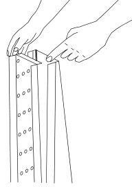
- Perform the conveyor removal steps described in Monthly Maintenance, paragraph “A”. After the conveyor is removed, lay it on a flat surface.
- Remove the two conveyor belts by disassembling the conveyor master links, as described in Monthly Maintenance, paragraph “H”. Then, remove the two conveyor belts by rolling them up.
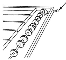
- Remove the conveyor adjustment bolts to allow the idler brackets to swing free.
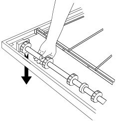
Figure 4-44. - Drop the idler shaft assembly clear of the frame through the front frame slot.
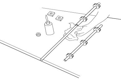
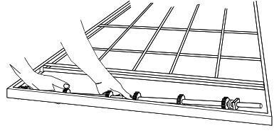
Figure 4-45. - Pull the front and rear shafts apart and apply oil to both the extended shaft and the interior of the hollow shaft. Using a rag, wipe oil off parts. Repeat until shafts are clean. Apply more oil to shafts then reassemble.
Figure 4-46. - Make sure bronze washer is in between the two halves.
Figure 4-47. - Place the idler shaft assembly back into place and reinstall the adjustment screws.
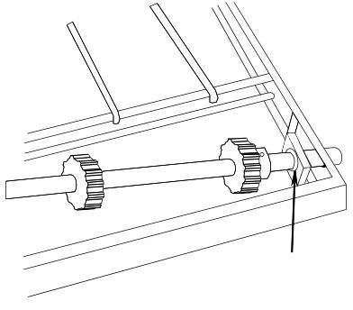
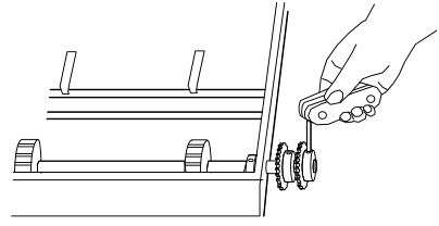
Figure 4-48. - Loosen the set screw on each conveyor drive sprocket and remove sprockets.
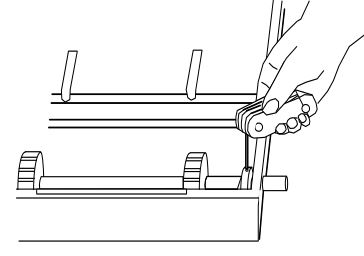
Figure 4-49. - Loosen the split locking collar.
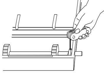
Figure 4-50. - Remove drive shafts by sliding to right then lifting the left side. Follow cleaning and lubricating procedures out-lined in Steps 4-6.
Figure 4-51. - Reassemble conveyor drive shafts into frame, making sure nylon spacer is in place.
Figure 4-52. - Slide shaft assembly to right side, holding assembly in place. Slide split locking collar to the left side and tighten.
- Slide rear conveyor drive sprocket onto shaft. Tighten the set screw of this drive sprocket until it extends into the hole of the hollow shaft. It should NOT touch the inner, solid shaft. Check to see that only the rear shaft moves when the sprocket is turned. If both shafts move, you have tightened the set screw too tight. Loosen the set screw until only the rear shaft moves when the sprocket is turning.
- Insert adaptor bushing into remaining drive sprocket then place onto shaft. Make sure nylon spacer is in place. Tighten set screw making sure screw goes through slot in adaptor bushing and locks onto shaft.
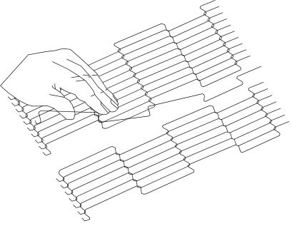
- Thread conveyor belts back onto frame making sure the links will be traveling in the proper direction.
- Follow conveyor reassembly instructions in Monthly Maintenance Paragraph “F”.


NOTE: It is recommended that the 6 Month Maintenance schedule be performed by a Middleby Marshall authorized service technician.
MAINTENANCE – EVERY 6 MONTHS
- Check brushes on D.C. conveyor motor, when worn to less than 1/10″ (2.4mm), replace the brushes.
- Clean and inspect the burner nozzle and electrode assembly. Also check your oven venting system.
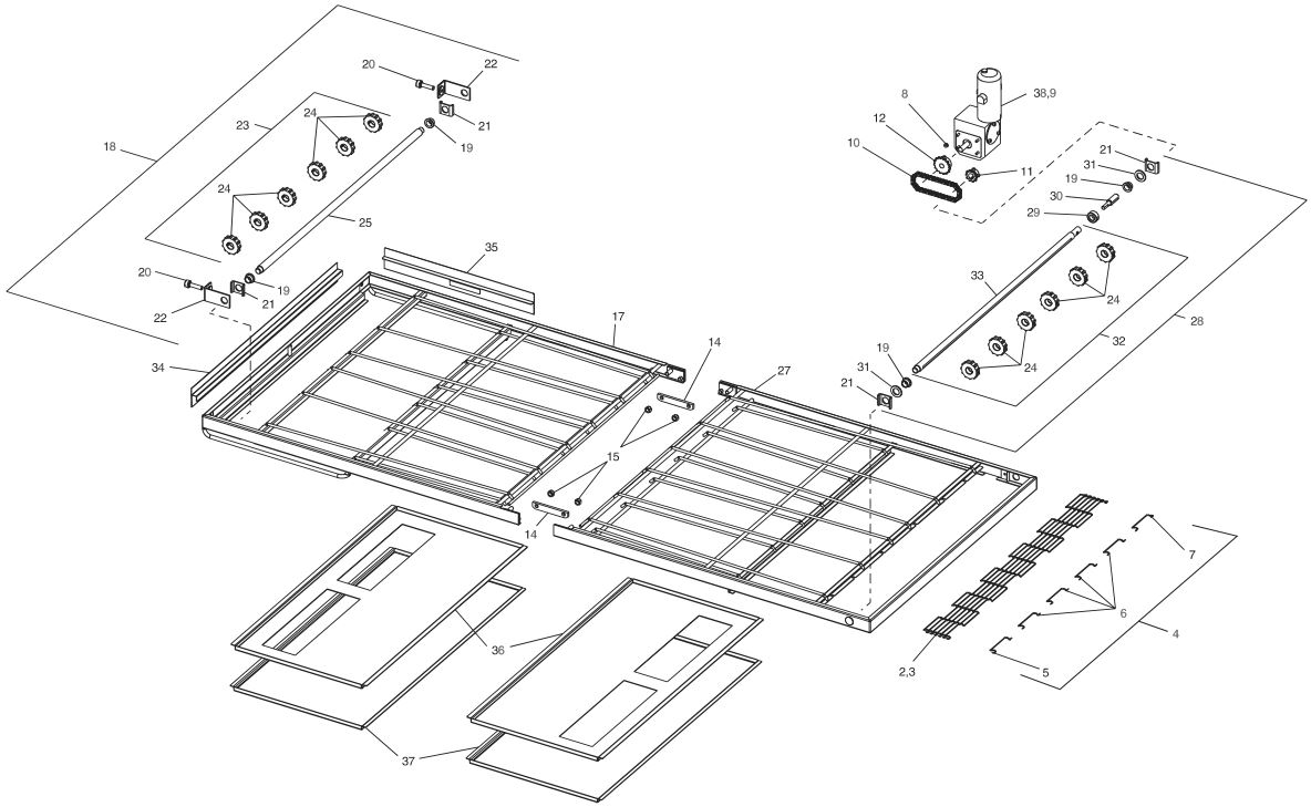
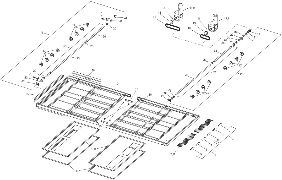
- Check conveyor shaft bushings and spacers. Replace them if they are worn. See Figure 6-5, Conveyor Exploded Drawing, items 15, 30 and 31 or Figure 6-6, Split Belt Conveyor, items 19, 23, 31, 35 and 36.
IMPORTANT NOTICES:
- Installation of replacement parts requiring access to the interior of the oven is permitted only by an authorized service technician.
- If there are any problems with the operation of the oven, the authorized service technician must be called.
- It is suggested to obtain a service contract with a manufacturer’s authorized service technician.

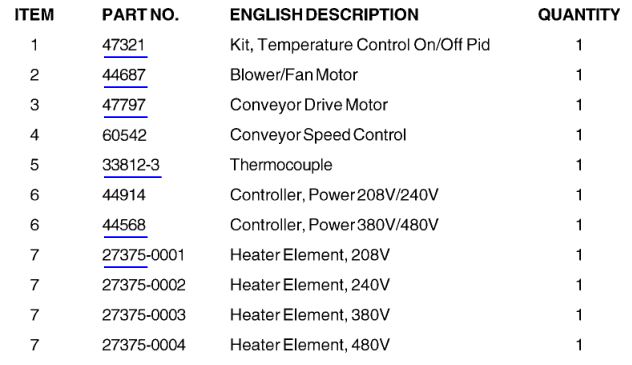
KEY SPARE PARTS KIT
An oven can be purchased with a Key Spare Parts Kit (Figure 4-56). (The kit can be purchased when the oven is ordered, or later, from a Middleby Marshall Authorized Parts Distributor). The kit contains many of the crucial parts that can reduce serious downtime and loss of production, if a failure occurs.
Replacement parts for this kit can be purchased from your Middleby Marshall Authorized Parts Distributor.
PS540-SERIES ELECTRIC OVEN KEY SPARE PARTS KIT (Figure 4-56)

SECTION 5 TROUBLESHOOTING

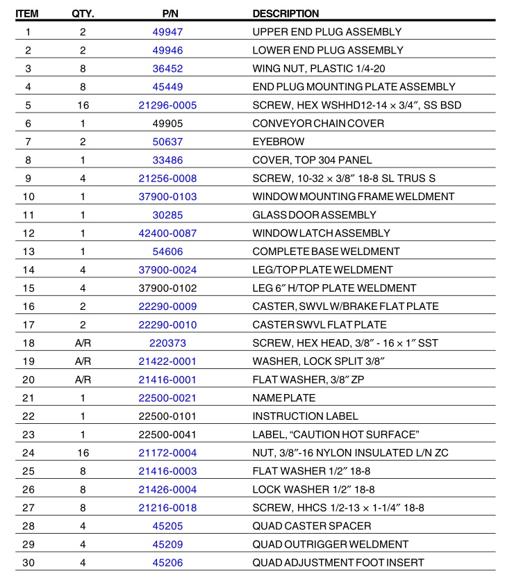
SECTION 6 – PARTS LIST
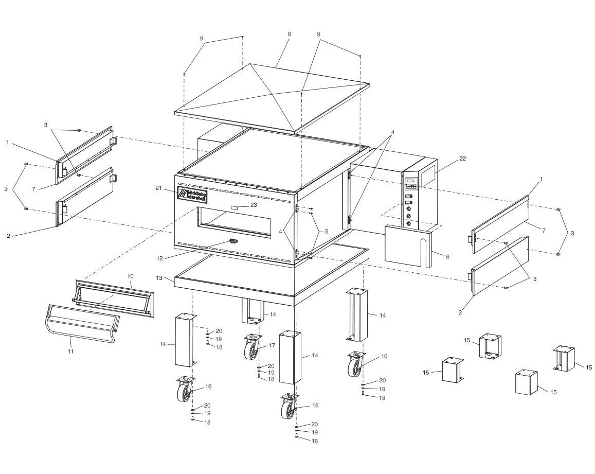
OVEN PANELS, WINDOW AND LEGS
CONTROL PANEL


BLOWER AND SHROUD
CONVEYOR
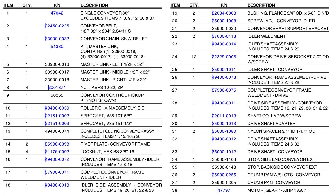
SPLIT BELT CONVEYOR

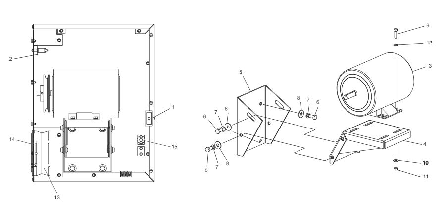
MACHINERY COMPARTMENT

SECTION 7 ELECTRICAL SCHEMATICS


WARNINGImproper installation, adjustment, alteration, service or maintenance can cause property damage, injury or death. Read the installation, operating and maintenance instructions thoroughly before installing or servicing this equipment.
NOTICEDuring the warranty period, ALL parts replacement and servicing should be performed by your Middleby Marshall Authorized Service Agent. Service that is performed by parties other than your Middleby Marshall Authorized Service Agent may void your warranty.
NOTICEUsing any parts other than genuine Middleby Marshall factory manufactured parts relieves the manufacturer of all warranty and liability.
NOTICEMiddleby Marshall reserves the right to change specifications at any time.
![]()
Middleby is proud to support the Commercial Food Equipment Service Association (CFESA). We recognize and applaud CFESA’s ongoing efforts to improve the quality of technical service in the industry.
Middleby Cooking Systems Group • 1400 Toastmaster Drive • Elgin, IL 60120 • USA • (847)741-3300 • FAX (847)741-440624-Hour Service Hotline: 1-(800)-238-8444www.middleby.com

Middleby Marshall PS540-Series Ovens PS540E User Manual – Middleby Marshall PS540-Series Ovens PS540E User Manual –
[xyz-ips snippet=”download-snippet”]