![]() ACCESS CONTROLS
ACCESS CONTROLS
 Wireless Gate Entry IntercomInstallation Instructions
IMPORTANT: Allow the intercom base unit’s battery to charge for 12 hours before using the system for the first time.Crystal clear two-way wireless communication up to 500 feetThank you for purchasing the Mighty Mule Wireless Gate Entry Intercom.Please read the directions carefully and completely before installing.SAFETY NOTE:NEVER install the keypad portion of this system where a person can reach through the gate to activate it, or where a person can touch the gate while activating the keypad.The recommended minimum distance between the gate and keypad is 10 ft.
 Features of the Wireless Intercom/Keypad
 Features of the Wireless Intercom/Keypad
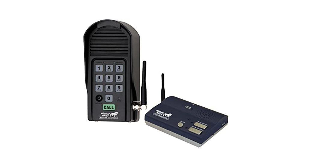
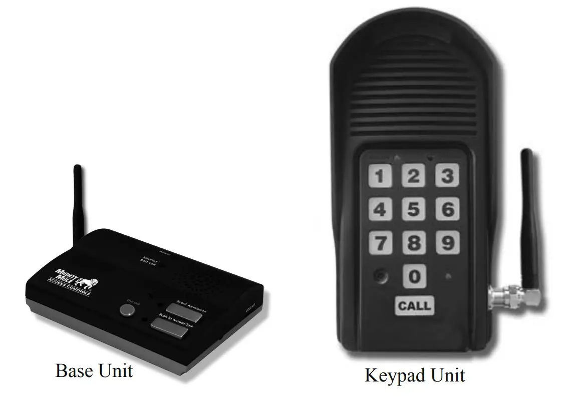
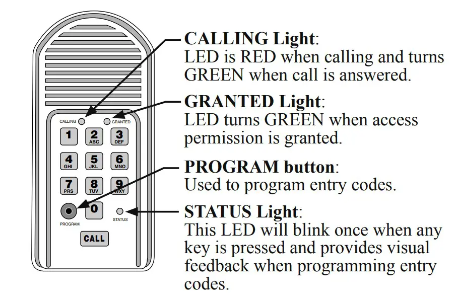
The Wireless Intercom/Keypad has two separate units: the KEYPAD and the BASE UNIT. The keypad should be mounted outside the gate allowing visitors to press the CALL button from their vehicle. The base unit is powered by a rechargeable battery; the charge is maintained by the transformer. It can also be disconnected from the transformer allowing it to go anywhere within range for convenience. Up to three additional base units can be added for convenience in different locations throughout the house.When someone without an access code approaches the gate, they can press the CALL button on the keypad which will ring the base unit inside the house. To answer the CALL, the person inside presses and holds the ANSWER button to talk to the person at the gate, releasing the ANSWER button to listen. To allow the person calling to open the gate, the GRANT PERMISSION button must be pressed. Then the person at the gate can press any number key on the keypad to open the gate. The END CALL button terminates the calls and the ON/OFF switch can be used to conserve power when using the unit on battery (note: the base station will not receive a signal if turned OFF).Up to 25 different personal Entry Codes may be programmed into the keypad, allowing you to give different temporary and permanent Entry Codes to different users. For example, you can give a delivery person their own temporary entry code, which you can easily change after he has made the delivery. This will prevent him from being able to regain access, while still allowing those to whom you gave permanent Entry Codes full access.After entering a valid code, pressing any key on the keypad while the gate is opening will stop the gate; pressing any key while the gate is stopped will cause the gate to reverse direction. The keypad will not affect the auto-close setting of your gate opener system.The keypad will light up and the unit will beep at the press of any key. The keypad memory will recognize your entry code in a string of up to 20 digits. If it finds the correct sequence, it will activate the gate opener. As a security feature, the keypad will shut down for 40 seconds if it does not find the correct code sequence within a 20-digit string. This will discourage an unauthorized person from trying to use random numbers to access your property.Entry Codes will remain stored in memory even when the batteries go dead. The keypad will remember your Entry Codes as long as you don’t press the RESET button.IMPORTANT: In areas of high radio frequency (RF) interference, the keypad may need to be connected (hard-wired) directly to the gate opener using 16 gauge (AWG) stranded, direct burial, low voltage wire (RB509, not included).FCC WARNING: Changes or modifications to this unit not expressly approved by the party responsible for compliance could void the user’s authority to operate the equipment.NOTE: This equipment has been tested and found to comply with the limits for a Class B digital device, pursuant to Part 15 of the FCC Rules. These limits are designed to provide reasonable protection against harmful interference in a residential installation. This equipment generates, uses and can radiate radio frequency energy and, if not installed and used in accordance with the instructions, may cause harmful interference to radio communications.However, there is no guarantee that interference will not occur in particular installations. If this equipment does cause harmful interference to radio or television reception, which can be determined by turning the equipment off and on, the user is encouraged to try to correct the interference by one or more of the following measures:
- Reorient or replace the receiver antenna.
- Increase the separation between the equipment and the receiver.
- Connect the equipment into an outlet on a circuitdifferent from that to which the receiver is connected.
- Consult the dealer or an experienced radio/TV technician for help.
The contents of all material available on this installation manual are copyrighted by Gates That Open, LLC (“GTO”), unless otherwise indicated. All rights are reserved by GTO, and content may not be reproduced, downloaded, disseminated, published, or transferred in any form or by any means, except with the prior, written permission of GTO. Any reprinting of GTO publications is by permission only. Copyright infringement is a violation of federal law.GTO®, GTO/PRO®, Mighty Mule® are registered trademarks of GTO – Gates That Open, LLC. GTO Access Systems™ is a trademark of GTO – Gates That Open, LLC. These marks are the exclusive property of GTO – Gates That Open, LLC (“GTO”). All rights are reserved by GTO, and these marks may not be used, in any form, without the prior, written permission of GTO.
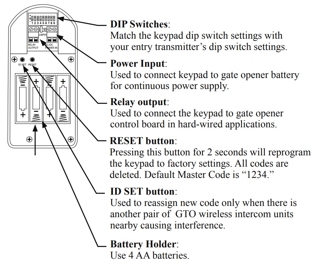
Keypad Description
|
Keypad Front |
Keypad Interior |
Install Batteries
Four (4) AA batteries (not included) are required to power the keypad. If an external DC power supply such as the gate opener’s battery is used (see 2.B.“Hard-Wired Installation”), the AA batteries will act as a backup.Step 1: Remove the two screws from the bottom of the keypad and separate the keypad from its housing.Step 2: Install four (4) AA batteries (not included).
Install Keypad
A. Wireless Installation
 |
 |
For wireless applications, the keypad must be in the line of sight of the gate opener receiver and no more than 50 ft. away from the receiver. Always test the keypad range before permanently mounting it.NOTE: a metal housing or metal object could cause interference.
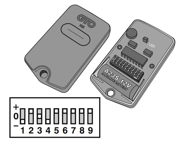
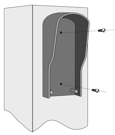
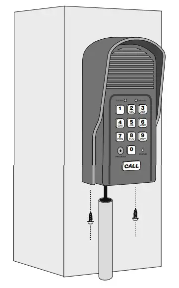
Step 1: Mount the keypad housing using the screws provided.Step 2: Set the keypad DIP switches to match your entry transmitter’s DIP switch settings.NOTE: If you have not adjusted your gate opener’s entry transmitter from the factory setting, see the “Personalize Transmitter Settings” section in the gate opener’s installation manual.Then set the keypad DIP switches to match the entry transmitter DIP switch setting.Step 3: Slide the keypad into the housing and secure it with the small screws provided.B. Hard-Wired Installation
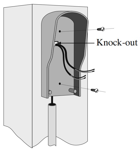 To power the keypad with the gate opener’s battery and hard wire the communication between the keypad and the gate opener, you will need to run two pairs of wires: one pair to hard-wire the keypad to the gate opener’s control board; the other pair to connect the keypad to the gate opener’s battery.Step 1: Turn the gate opener’s power switch OFF. Use two pairs of 16 gauge (AWG) stranded, direct burial, low voltage wire (RB509) to connect the keypad to the gate opener control board and battery. Run the wire through the PVC pipe from the ground to the keypad and from the ground to the opener control board to protect it from lawnmowers or grazing animals.Determine how the wires will enter the keypad (e.g., from the back through a hole drilled in the post; running the wire on the post surface). Remove the small rectangular knock-out on the back of the keypad housing and pull the wires into the housing. Then mount the housing to the post using the screws provided.Step 2: Strip 3/16″ off the ends of one pair of low-voltage wires. Attach the wires to the terminal block marked RELAY OUTPUT on the keypad control board as shown. Connect the other end of the wires to the gate opener’s control board as shown in Control Board Connections (below).Step 3: Strip 3/16″ off the ends of the second pair of low voltage wires.Attach the wires to the terminal block marked AC/DC POWER IN on the keypad control board as shown. Connect the other end of the wires to the opener’s battery: one end to the POSITIVE (RED) pole and the other to the NEGATIVE (BLACK) pole.Jumper OFF wireless mode Jumper ON wired mode
|
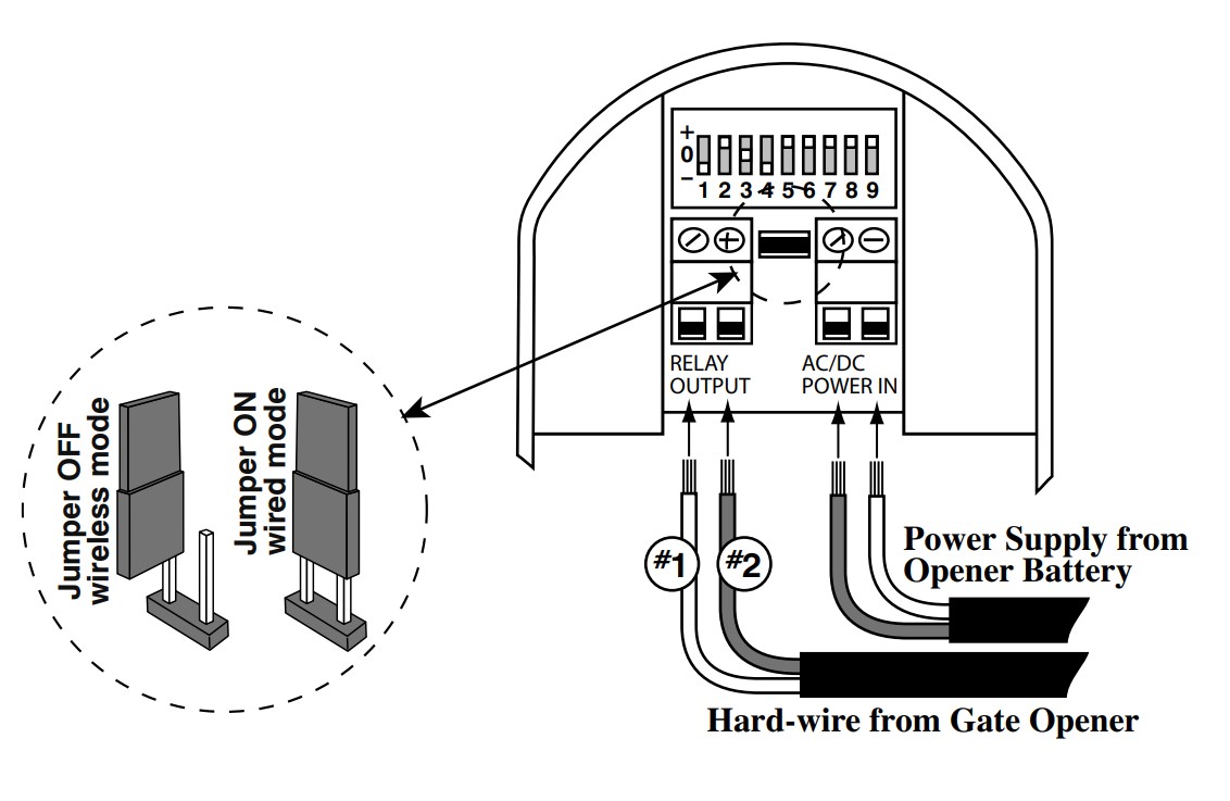 |
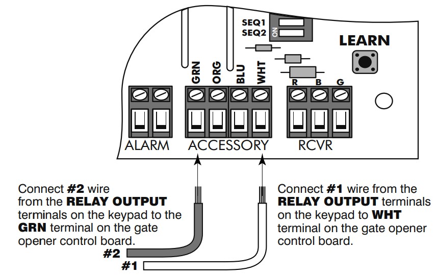
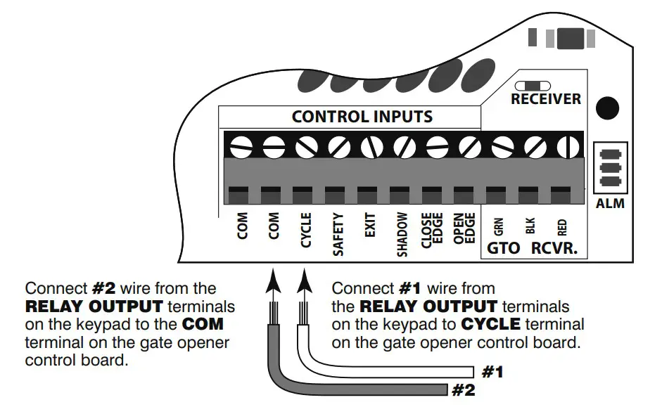
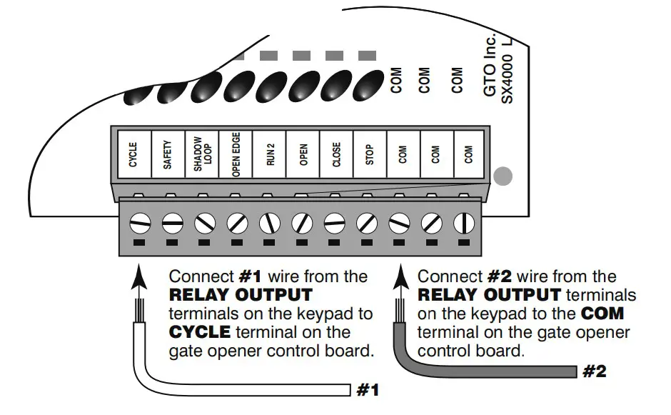
Step 4: Connect the jumper between the two terminals on the keypad control board (ON) as shown.Step 5: Slide the keypad into the housing and secure it with the small screws provided.Step 6: Replace the control board cover and turn the power switch ON.Control Board ConnectionsIf your control board doesn’t look like any of these diagrams, please refer to your gate opener installation manual or call GTO Technical Service at 1-800-543-1236 or 850-575-4144.
|
PRO-1000/2000, PRO-SL1000/SL2000, and Old Mighty Mule Control Boards |
Mighty Mule 350 Control Board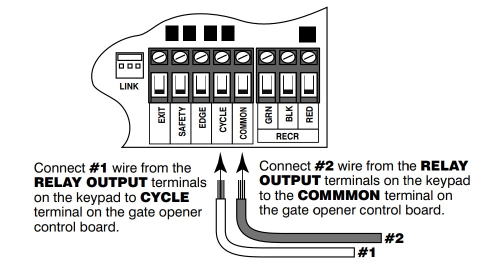 |
Mighty Mule 500 & 502 Control Boards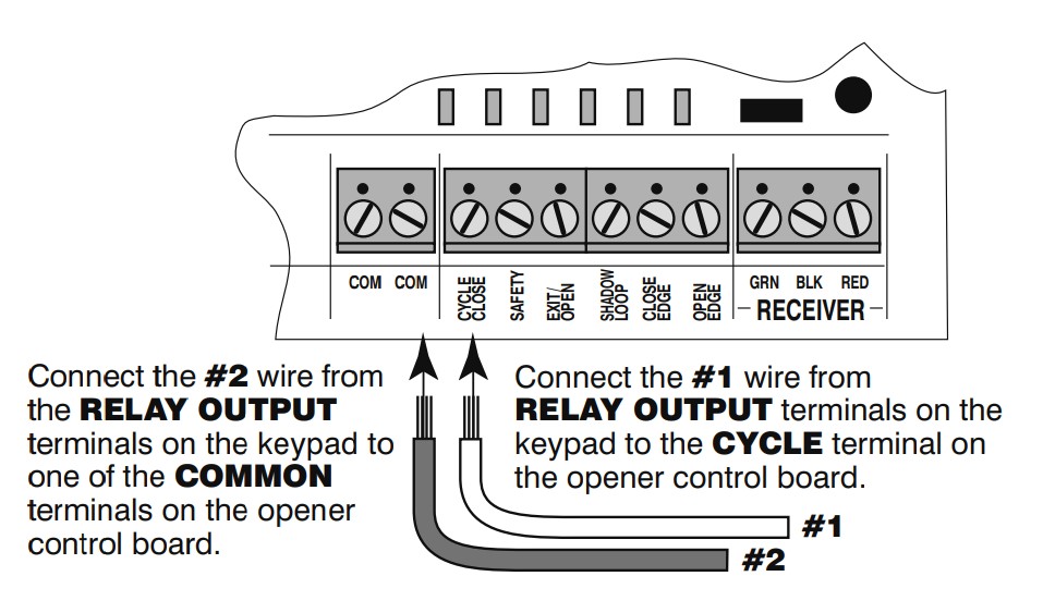 |
GEN-3 (Blue) Control Boards |
GTO/PRO DC Powered PRO-SW3000 and PRO-SW4000 Control Boards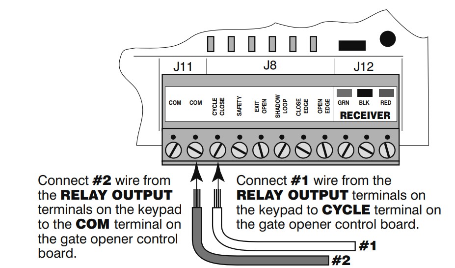 |
GTO/PRO GP-SL100 and GP-SW100 Control Boards |
Test Keypad
Turn the gate opener power switch to ON. Test the keypad by entering “1234.”
Program the Keypad
Programming Interface/Keypad Operation:
- In these instructions, the symbol for the Programming Button is:
- All codes are four (4) digits in length.
- Entry Code is a four (4) digit code needed to activate the gate.
- Master Code is needed to add, remove or reset Entry Codes.
- Master Code also functions as an Entry Code.
- Factory default Master Code is “1234.”
- The STATUS light should blink and the keypad should beep (once) whenever any button is pressed.
- If more than 10 seconds elapse between key presses, the keypad returns to idle mode.
- The keypad can only enter program mode from idle mode.
- The keypad will beep three times before going into idle mode.
- When a programmed Entry Code is used, the keypad STATUS light will blink twice and the keypad will beep twice to confirm that a matched code is entered.
- No more than 20 key presses are allowed to obtain a 4-digit Entry Code. For example, “1234” is one of the programmed Entry Codes. The user can enter “x1234” or“xxxxxxxxxxxxxxxx1234” (with “x” being any key) and the gate will be activated. If more than 20 key presses are entered without matching one of the Entry Codes, then the STATUS light will flash rapidly and the keypad will go into “lock-down” mode for 40 seconds. The user must not enter any code for at least 40 seconds before the unit returns to idle mode.
Add Temporary Entry Code:
- Press and release the PROGRAM button.
- Enter the Master Code then press and release the PROGRAM button.
- Enter “8” and any number between 1 thru 7 then press and release the PROGRAM button. The second number (1 thru 7) indicates the number of days after which the code will be automatically removed from memory.*
- Enter the new Entry Code then press and release the PROGRAM button. The keypad will beep 3 times to confirm that the new Entry Code is accepted.**Example: Keypress sequence to add “3456” as a temporary Entry Code that will remain valid for only three days (“1234” is the Master Code).

*NOTE: If memory is full (there are already 25 programmed Entry Codes) the STATUS light will flash rapidly and the Keypad will beep for 2 seconds before returning to idle mode without saving.**NOTE: If the code is NOT 4-digits in length or an error has occurred, the STATUS light will flash rapidly and the keypad will beep for 2 seconds before returning to idle mode without saving.
Program New Master Code:
- Press and release the PROGRAM button.
- Enter the old Master Code, then press and release the PROGRAM button.
- Enter “06” then press and release the PROGRAM button.
- Enter the new Master Code, then press and release the PROGRAM button.
- Enter the new Master Code again for confirmation, then press and release the PROGRAM button.
- The keypad beeps 3 times to confirm that the new Master Code is accepted.NOTE: If the new Master Code is not a matched pair or an error occurs (e.g., if the entry code is NOT a 4-digit code), the STATUS light will flash rapidly and the keypad will beep for 2 seconds before returning to idle mode with old Master Code.Example: Keypress sequence to change Master Code from “1234” to “3121.”
Delete An Entry Code:
- Press and release the PROGRAM button.
- Enter the Master Code then press and release the PROGRAM button.
- Enter “03” then press and release the PROGRAM button.
- Enter the Entry Code to be deleted, then press and release the PROGRAM button. The keypad will beep 3 times to confirm that the Entry Code is deleted.NOTE: If no matching code is found or the code is NOT 4-digit in length, then an error has occurred. The STATUS light will flash rapidly and the keypad will beep for 2 seconds before returning to idle without saving.Example: Keypress sequence to delete entry code “3456” from memory (“1234” is the Master Code).

Add New Entry Code:
- Press and release the PROGRAM button.
- Enter the Master Code, then press and release the PROGRAM button.
- Enter “02” then press and release the PROGRAM button.*
- Enter the new Entry Code, then press and release the PROGRAM button. The keypad will beep 3 times to confirm that the new Entry Code is accepted. **Example: Keypress sequence to add “3456” as a new entry code (“1234” is the Master Code).

Delete ALL Entry Codes:
- Press and release the PROGRAM button.
- Enter the Master Code then press and release the PROGRAM button.
- Enter “07” then press and release the PROGRAM button. The keypad will beep 3 times to confirm that all Entry Codes are deleted.Example: Keypress sequence to delete all entry codes from memory (“1234” is the Master Code).

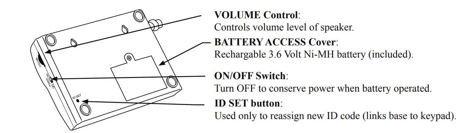
Base Unit Description
Base Unit Face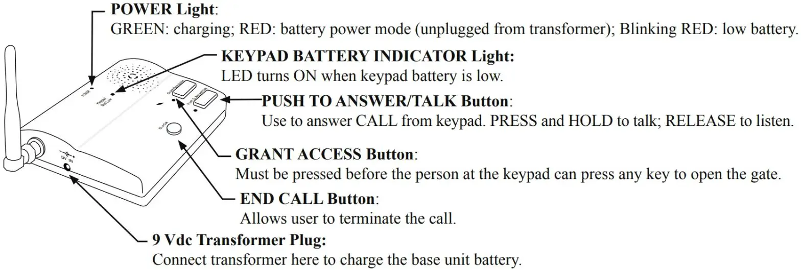 |
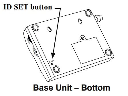
Base Unit Bottom |
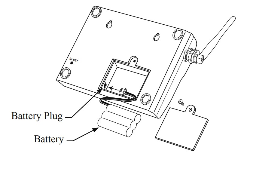
Install Base Unit Battery
Step 1: Remove the battery access cover using a small Phillips head screwdriver.Step 2: Plug the rechargeable Ni-MH battery into the receptacle inside the battery compartment.Step 3: Replace the battery access cover.
Connect the Transformer
Step 1: Find a convenient location near an outlet to mount or place the base unit. If you are mounting the base unit on the wall, use the template (page 6) to place screws.Step 2: Plug the transformer into the AC outlet and connect it to the base unit’s power jack marked DC 9V.IMPORTANT: Allow the base unit’s battery to charge for 12 hours before using the system for the first time.

The base unit can be disconnected from the transformer for use in another location. The battery will last approximately four (4) hours when unplugged from the transformer. IMPORTANT: You can turn the base unit OFF to conserve battery power, however it will not receive a signal when OFF.
Add Additional Base Units (optional)
Intercom ID CodesThe keypad and base unit are programmed at the factory to communicate with each other and do not need the ID Codes programmed. This base unit is the MASTER or #1 unit.If you have purchased additional base units (F3101MBC) to enhance your system, each additional unit’sID Code must be programmed into the keypad so they can communicate.
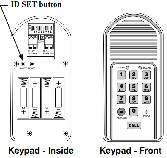
Step 1: Install the battery and turn the base unit ON.Step 2: Press and release the “ID SET” button on the keypad.Step 3: Press the number on the keypad that corresponds to the base unit you are adding. You will hear a number of beeps corresponding to the number you pressed. For Example: if you are adding a second base unit to the system, PRESS “2,” the keypad will beep TWO times.Step 4: Press the “ID SET” button on the base unit for approximately two seconds then release. You will hear TWO beeps from the base unit and TWO beeps from the keypad, which means the ID Code is set.IMPORTANT: Base units need to be placed at least 10 feet apart to prevent interference.
Test the System
IMPORTANT: The base unit and the keypad cannot be within 30 feet of each other when operating. If units are closer than 30 feet the signal will be inconsistent and emit speaker feedback. Also, multiple base units must be no closer than 10 feet from each other to prevent interference.Have someone press the CALL button on the keypad at the gate. When the base unit inside the house rings, press the ANSWER button and talk to the person at the gate to check the connection and range. Then press the GRANT PERMISSION button and have the person at the gate press any key on the keypad to activate the gate.
Troubleshooting
Make sure all connections are secure and correct, batteries installed, and the base unit is ON. If you have multiple base units, they should be at least 10 feet apart to prevent interference.In rare cases, other devices operating in the same frequency band may cause interference with the intercom signal. If the system does not communicate at all, reassign the base unit/keypad ID code as follows (this will require two people):
 report this ad
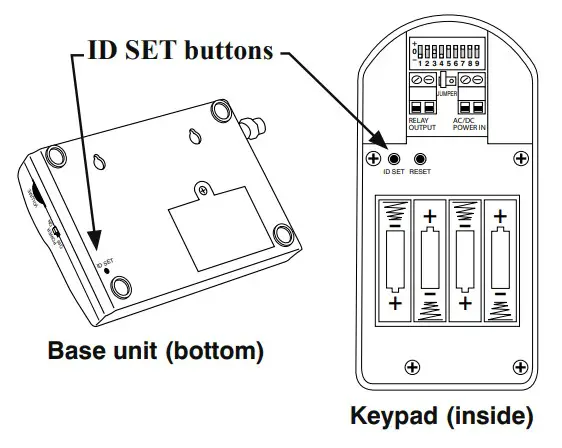
- Open the keypad and locate the “ID SET” button above the batteries. Locate the “ID SET” button on the bottom of the intercom base unit.
- Make sure the “antenna-to-antenna” distance between the keypad and the base unit is at least 30 feet.
- Press the “ID SET” button on the keypad until you hear a beep, then release. This erases all stored ID Codes.
- Press the “ID SET” button on the MASTER base unit for approximately 2 seconds then release. You will hear ONE beep from the base unit and TWO from the keypad, which means the ID Codes are reassigned.
- Test the system by pressing the CALL button on the keypad to see if the base unit receives the signal. Once the system is working, you will need to reset additional base stations (see page 5).
If all connections are correct and the ID SET change didn’t solve the communication problem, please call our Technical Service Department at 1-800-543-1236, Monday–Friday, 8:00 am to 7:00 p.m. (ET).
|
INTERCOM/KEYPAD SPECIFICATIONS |
|
| Frequency | 318 MHz from the keypad to gate opener900 MHz from the keypad to the base station |
| Memory – Keypad | Stores up to 25 four-digit entry codes |
| Power Consumption – Keypad | 60 mA when the relay is closed |
| Power Supply – Keypad | 8-24 Vdc or four AA batteries |
| Power Supply – Base Unit | 9 Vdc 300 ma transformer: 3.6V Ni-MH 800 mA rechargeable battery pack |
| Range from Keypad to Base Unit | 500′ wireless |
| Range from Reypad to Gate Opener | 50′ wireless 100′ wired using 16 AWG wire |
| Relay Output – Keypad | Momentary, normally open dry contact closes for 2 seconds upon activation |
| Relay Output Rating – Keypad | 12 or 24 Vdc 100 mA |
| Wiring – Keypad Power & Relay Output | 16 AWG stranded low voltage direct burial wire |
Limited One Year Warranty
Gates That Open, LLC (“GTO”). gate opener accessories are warranted by the manufacturer against defects in workmanship for a period of one (1) year from the date ofpurchase, provided recommended installation procedures have been followed.In the case of product failure due to defective material or manufacturer workmanship within the one (1) year warranty period, the accessory will be repaired or replaced (at the manufacturer’s option) at no charge to the customer, if returned freight prepaid to GTO – Gates That Open, LLC • 3121 Hartsfield Rd. • Tallahassee, FL 32303.IMPORTANT: Call 850/575-4144 or fax 850/575-8950 for a Return Goods Authorization (RGA) number before returning goods to the factory. Products received at the factory without an RGA will not be accepted. Replacement or repaired parts are covered by this warranty for the remainder of the one (1) year warranty period. GTO will pay the shipping charges for return to the owner of items repaired.The manufacturer will not be responsible for any charges or damages incurred in the removal of the defective parts for repair, or for the reinstallation of those parts after repair. This warranty shall be considered void if damage to the product(s) was due to improper installation or use, connection to an improper power source, tampering, or if the damage was caused by lightning, electrical power surge, wind, fire, flood, insects, or another natural agent.After the one (1) year warranty period, GTO or one of its authorized service centers will make any necessary repairs for a nominal fee. Call GTO at 850/575-4144 for more information. This warranty gives you specific legal rights, and you may also have other rights which may vary from state to state. This warranty is in lieu of all other warranties, expressed or implied.NOTE:Verification of the warranty period requires copies of receipts or other proof of purchase. Please retain those records.If you have any questions or concerns, please contact our Technical Service Department Monday thru Friday 8:00 a.m. to 7:00 p.m. (ET) at 1-800-543-1236 or 850-575-4144
![]() GTO–Gates That Open, LLC3121 Hartsfield RoadTallahassee, Florida 32303Telephone (850) 575-0176Fax (850) 575-8912www.gtoinc.com
GTO–Gates That Open, LLC3121 Hartsfield RoadTallahassee, Florida 32303Telephone (850) 575-0176Fax (850) 575-8912www.gtoinc.com
References
[xyz-ips snippet=”download-snippet”]