
![]()
hAP ac lite
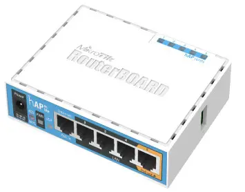
The hAP ac lite is a simple home wireless access point. It is configured out of the box, you can simply plug in your internet cable and start using wireless internet. We recommend you to set up a password to secure your device, follow these steps.
QuickstartMake sure that your ISP is allowing hardware change, please follow these quick steps to set up your device:
- Connect your ISP Ethernet cable to the Ethernet port 1.
- Connect the device to the power source (see “Powering”).
- Open network connections on your PC, mobile phone, or other device and search for MikroTik wireless network and connect to it.
- The Configuration has to be done through the wireless network using a web browser or mobile app – (see“MikroTik mobile app”). Alternatively, you can use WinBox configuration tool http://mt.lv/winbox.
- Once connected to the wireless network, open http://192.168.88.1 in your web browser to start configuration, user name: admin and there is no password by default.
- When using a mobile application choose Quick setup and it will guide you through all necessary configurations in six easy steps.
- We recommend clicking the “Check for updates” button and updating your RouterOS software to the latest version to ensure the best performance and stability.
- Choose your country, to apply country regulation settings, and set up your password in the screen that loads.
MikroTik mobile app
Use the MikroTik smartphone app to configure your router in the field, or to apply the most basic initial settings foryour MikroTik home access point.
- Scan QR code and choose your preferred OS.
- Install and open application.
- By default, the IP address and user name will be already entered.
- Click Connect to establish a connection to your device through a wireless network.
- Choose Quick setup and application will guide you through all basic configuration settings in a couple of easy steps.
- Advanced menu is available to fully configure all necessary settings.

https://mikrotik.com/mobile_app
PoweringThe device accepts power from the power jack or from the first Ethernet port (Passive PoE):
- Direct-input power jack (5.5 mm outside and 2 mm inside, female, pin positive plug) accepts 10-30 V DC.
- First Ethernet port accepts passive Power over Ethernet accepts 12-30 V DC.
The power consumption under maximum load can reach 5 W. The Ether5 port supports PoE output for powering other RouterBOARD devices. The port has the auto-detection feature, so you can connect Laptops and other non-PoE devices without damaging them. The PoE on Ether5 outputs approximately 2 V below input voltage and supports up to 0.58A (So provided 24 V PSU will provide 22V/0.58 A output to the Ether5 PoE port).
See mikrotik.com/products for the latest version of this document.
Document #40860 Modified on: 20.JAN.2020
ConfigurationOnce logged in, we recommend clicking the “Check for updates” button in the QuickSet menu, as updating your RouterOS software to the latest version ensures the best performance and stability. For wireless models, please make sure you have selected the country where the device will be used, to conform with local regulations. RouterOS includes many configuration options in addition to what is described in this document. We suggest starting here to get yourself accustomed to the possibilities: http://mt.lv/help. In case IP connection is not available, the Winbox tool (http://mt.lv/winbox) can be used to connect to the MAC address of the device from the LAN side (all access is blocked from the Internet port by default). For recovery purposes, it is possible to boot the device for reinstallation, see section Buttons and Jumpers.
MountingThe device is designed to be used indoors and placed on a flat surface with all needed cables connecting to the front of the unit.Alternatively unit can be mounted on the wall, mounting points are located on the bottom side of the device, screws are not included in the package. Screws with size 4×25 mm fit nicely, depending on your wall structure you can use dowels 6×30 mm and 6 mm drill bit if needed.![]() When mounting on the wall, please ensure that cable feed is pointing downwards. The IP rating scale of this device is IPX0. We recommend using Cat6 shielded cables. Warning! This equipment should be installed and operated with a minimum distance of 20 cm between the device and your body. Operation of this equipment in the residential environment could cause radio interference.
When mounting on the wall, please ensure that cable feed is pointing downwards. The IP rating scale of this device is IPX0. We recommend using Cat6 shielded cables. Warning! This equipment should be installed and operated with a minimum distance of 20 cm between the device and your body. Operation of this equipment in the residential environment could cause radio interference.
Extension Slots and Ports
- Five individual 10/100 Ethernet ports, supporting automatic cross/straight cable correction (Auto MDI/X), so you can use either straight or cross-over cables for connecting to other network devices.
- Integrated Wireless 2.4 GHz and 5 GHz 802.11 a/b/g/n/ac, simultaneous dual-band radio with onboard PIF antennas, max gain 1.5 dBi.
Buttons and JumpersThe reset button has the following functions:
- Hold this button during boot time until LED light starts flashing, release the button to reset RouterOS configuration (total 5 seconds).
- Keep holding for 5 more seconds, LED turns solid, release now to turn on CAP mode. The device will now look for a CAPsMAN server (total 10 seconds).
- Or Keep holding the button for 5 more seconds until until LED turns off, then release it to make the RouterBOARD look for Netinstall servers (total 15 seconds).
Regardless of the above option used, the system will load the backup RouterBOOT loader if the button is pressed before power is applied to the device. Useful for RouterBOOT debugging and recovery.
AccessoriesPackage includes the following accessories that come with the device:
- EU Switching Power Supply 24 V.
SpecificationsFor more information about this product, specifications, pictures, downloads, and test results please visit our webpage: https://mikrotik.com/product/RB952Ui-5ac2nDOperating system supportThe device supports RouterOS software version 6. The specific factory-installed version number is indicated in theRouterOS menu /system resource. Other operating systems have not been tested.
Federal Communication Commission Interference StatementFCC identifier: TV7RB952-5AC2NDThis equipment has been tested and found to comply with the limits for a Class B digital device, pursuant to Part 15 of the FCC Rules. These limits are designed to provide reasonable protection against harmful interference in a residential installation.![]() This equipment generates, uses, and can radiate radio frequency energy and, if not installed and used in accordance with the instructions, may cause harmful interference to radio communications. However, there is no guarantee that interference will not occur in a particular installation. If this equipment does cause harmful interference to radio or television reception, which can be determined by turning the equipment off and on, the user is encouraged to try to correct the interference by one of the following measures:
This equipment generates, uses, and can radiate radio frequency energy and, if not installed and used in accordance with the instructions, may cause harmful interference to radio communications. However, there is no guarantee that interference will not occur in a particular installation. If this equipment does cause harmful interference to radio or television reception, which can be determined by turning the equipment off and on, the user is encouraged to try to correct the interference by one of the following measures:
- Reorient or relocate the receiving antenna.
- Increase the separation between the equipment and receiver.
- Connect the equipment into an outlet on a circuit different from that to which the receiver is connected.
- Consult the dealer or an experienced radio/TV technician for help.
FCC Caution: Any changes or modifications not expressly approved by the party responsible for compliance could void the user’s authority to operate this equipment. This device complies with Part 15 of the FCC Rules. Operation is subject to the following two conditions: (1) This a device may not cause harmful interference, and (2) this device must accept any interference received, including interference that may cause undesired operation. This device and its antenna must not be co-located or operation inconjunction with any other antenna or transmitter.IMPORTANT: Exposure to Radio Frequency Radiation. 20 cm minimum distance has to be maintained between the antenna and user. Under such a configuration, the FCC radiation exposure limits set forth for a population/uncontrolled environment can be satisfied. Antenna Installation.WARNING: It is installer’s responsibility to ensure that when using the authorized antennas in the United States (or where FCC rules apply); only those antennas certified with the product are used. The use of any antenna other than those certified with the product is expressly forbidden in accordance to FCC rules CFR47 part 15.204. The installer should configure the output power level of antennas, according to country regulations and per antenna type. Professional installation is required of equipment with connectors to ensure compliance with health and safety issues.
Innovation, Science and Economic Development CanadaThis device contains license-exempt transmitter(s)/receiver(s) that comply with Innovation, Science, and EconomicDevelopment Canada’s license-exempt RSS(s). Operation is subject to the following two conditions:
- This device may not cause interference;
- This device must accept any interference, including interference that may cause undesired operation of the device.
IMPORTANT: Exposure to Radio Frequency Radiation.This equipment complies with the IC radiation exposure limits set forth for an uncontrolled environment. This equipment should be installed and operated with a minimum distance of 20 cm between the radiator and any part of your body.
CAN ICES-3 (B)/NMB-3(B)IC: 7442A-9525ACThe device for operation in the band 5150–5250 MHz is only for indoor use to reduce the potential for harmful interference to co-channel mobile satellite systems.
CE Declaration of Conformity![]() Manufacturer: Mikrotik SIA, Brivibas gatve 214i Riga, Latvia, LV1039.
Manufacturer: Mikrotik SIA, Brivibas gatve 214i Riga, Latvia, LV1039.
Hereby, Mikrotīkls SIA declares that the radio equipment type RouterBOARD is in compliance with Directive 2014/53/EU. The full text of the EU declaration of conformity is available at the following internet address: https://mikrotik.com/products
MPE statementThis equipment complies with EU radiation exposure limits set forth for an uncontrolled environment. This equipment should be installed and operated with a minimum distance of 20 cm between the radiator and your body unless specifically stated otherwise on page 1 of this document. In RouterOS you must specify your country, to make sure local wireless regulations are observed.
Frequency bands terms of use
| Frequency range (for applicable models) | Channels used | Maximum Output Power (EIRP) | Restriction |
| 2412-2472 MHz | 1 – 13 | 20 dBm | Without any restriction to use in all EU Member States |
| 5150-5250 MHz | 26 – 48 | 23 dBm | Restricted to indoor use only* |
| 5250-5350 MHz | 52 – 64 | 20 dBm | Restricted to indoor use only* |
| 5470-5725 MHz | 100 – 140 | 27 dBm | Without any restriction to use in all EU Member States |
* It is the customer’s responsibility to follow local country regulations, including operation within legal frequency channels, output power, cabling requirements, and Dynamic Frequency Selection (DFS) requirements. All Mikrotik radio devices must be professionally installed!Note. Information contained here is subject to change. Please visit the product page on www.mikrotik.com for the most up-to-date version of this document.

 report this ad
Instruction manual: Connect the power adapter to turn on the device. Open 192.168.88.1 in your web browser, to configure it. More information on https://mt.lv/help
References
MikroTik Routers and Wireless – Products
Manual:TOC – MikroTik Wiki
MikroTik Routers and Wireless – Products
MikroTik Routers and Wireless
MikroTik Routers and Wireless
MikroTik Routers and Wireless – Products: hAP ac lite
MikroTik Routers and Wireless – Products
MikroTik Routers and Wireless
Labelled content – User manuals – MikroTik Documentation
Labeled content – User manuals – MikroTik Documentation
MikroTik Routers and Wireless – Products: hAP ac²
Pages – User manuals – MikroTik Documentation
User Manuals – User manuals – MikroTik Documentation
MikroTik Wiki
hAP ac² – User manuals – MikroTik Documentation
Atlassian | Software Development and Collaboration Tools
Wireless for home and office – User manuals – MikroTik Documentation
MikroTik Routers and Wireless
hAP ac – User manuals – MikroTik Documentation
MikroTik Routers and Wireless – Products: hAP ac
Labelled content – User manuals – MikroTik Documentation
Pages – User manuals – MikroTik Documentation
Manual:TOC – MikroTik Wiki
hAP ac – User manuals – MikroTik Documentation
MikroTik Routers and Wireless
Wireless for home and office – User manuals – MikroTik Documentation
User Manuals – User manuals – MikroTik Documentation
MikroTik Routers and Wireless – Products
Labeled content – User manuals – MikroTik Documentation
MikroTik SFP module compatibility table – MikroTik Wiki
MikroTik Routers and Wireless
Atlassian | Software Development and Collaboration Tools
[xyz-ips snippet=”download-snippet”]