MikroTikHeavy-Duty Weatherproof Design ModemUser Guide

LtAP LR8 LTE kit (RBLtAP-2HnD&R11e-LTE&LR8)
Quick Start
Please follow these quick steps to set up your device:
- Open the bottom lid;
- Insert the SIM card into the SIM 2 slot (middle);
- Connect the device to the power source;
- Connect with your computer to the MikroTik wireless network;
- Open https://192.168.88.1 in your web browser to start the configuration;
- The user name: admin and there is no password set, by default;
- Once connected, in the QuickSet LTE AP menu, enter your PIN code https://mt.lv/configuration;
- Upgrade the RouterOS software to the latest version https://mt.lv/upgrade;
- Connect again and in the QuickSet LTE AP menu set your wireless network password;
- Choose your country on the left side of the screen, to apply country regulation settings;
- Secure your device and set a strong password.
- Find your LR Gateway ID on the label within the product and register it in your Network Server.
Extension slots and ports
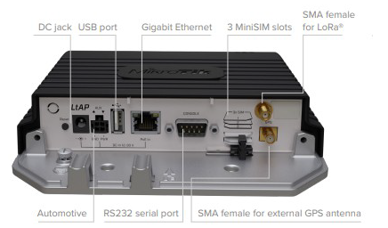
- Built-in 2 GHz wireless access point module, AP/station/bridge/p2p modes are supported. Onboard PIF antennas built-in, as well as MMCX connectors for external antennas (software selectable).
- Two miniPCIe slots and three SIM slots.
- Built-in GPS module with an external SMA connector.
- Gigabit Ethernet port, supporting automatic cross/straight cable correction (Auto MDI/X). Either straight or crossover cable can be used for connecting to other network devices. The Ethernet port accepts 12-30 V DC powering from a passive PoE injector.
- One DB9 RS232 serial port for serial console access. Configured as 115200 bit/s, 8 data bits, 1 stop bit, no parity.
- One USB 2.0 port.
- R11e-LR8, miniPCIe card with external SMA connector.
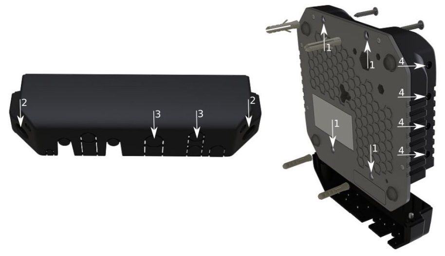
Mounting
- 1. It is possible to attach the device to a wall, using the provided four screws and designed four holeson the unit.
- The ports are protected with a small door, that is held in place with two screws. Remove to accessEthernet ports, antenna connector, SIM slots, etc.
- The door has cut-out places for all available ports, so you can guide through all necessary cables,but please only break out the openings that you will use.
- Several places for external antennas are provided on the case, use an appropriate size drill, to makethem available. Be careful and measure the chosen antenna, so that it does not touch the internalPCB board when installed.
The device can be used both indoors and outdoors. The IP rating scale of IP54.If you intend to mount outdoors, please ensure that any cable openings are directed downwards. The Mounting direction is indicated on the device with an arrow pointing up. Use POE injector and proper grounding. Recommended using Cat6 shielded cable.
Warning! This equipment should be installed and operated with a minimum distance of 30 cm
between the device and your body. Operation of this equipment in the residential environment could cause radio interference.
The device enclosure has places where you can drill openings for external LTE and GPS antennas. Use a drill to make holes that are appropriate for the antenna cable used.
Configuration
We recommend clicking the “Check for updates” button and updating your RouterOS software to the latest version to ensure the best performance and stability. RouterOS includes many configuration options in addition to what is described in this document. We suggest starting here to get yourself accustomed to the possibilities: https://mt.lv/help. In case IP connection is not available, the Winbox tool (https://mt.lv/winbox) can be used to connect to the MAC address of the device from the LAN side (all access is blocked from the internet port by default). For recovery purposes, it is possible to boot the device from a network, see the section LtAP kit-series#Reset button.
GPS
The built-in GPS module requires an external antenna to be used (SMA connector is already mounted behind the unit door). Please see the LtAP kit-series#Mounting section on how to remove the door.Attention the GPS uses an active antenna, only connect and disconnect the antenna, when the device is turned off!
Supports – GPS, GLONASS, BeiDou, Galileo).
Make sure that the GPS package is installed on your device. Check by following command /system package print. If not installed please download extra packages at our download page accordingly to your RouterOS version and install the GPS package by dragging it to the Files menu. Enable GPS and start working:
- Enabling – /system GPS set enable=yes;
- Setting antenna to external – /system GPS set GPS-antenna-select=external;
- Checking configuration – /system gGPS print.
https://wiki.mikrotik.com/wiki/Manual:System/GPS
LR usage
For interface configuration please visit https://wiki.mikrotik.com/wiki/Manual:Interface/LoraWe recommend using our antenna kit, https://mikrotik.com/product/lora_antenna_kit
USB usage
When using an LR card the USB port power will be switched off by the CPU. It cannot be used together with an LR card.
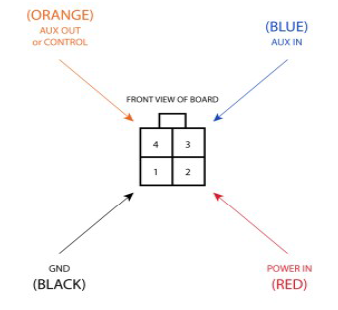
Automotive connector usage
Powering
Direct-input power jack (5.5 mm outside and 2 mm inside, female, pin positive plug) accepts 12-30V DC ⎓ with provided 24 V, 1.2 A adapter.
- Ethernet port accepts passive Power over Ethernet 12-30 V DC ⎓ (compensate for the loss on cable, so more than 12 V recommended).
- The automotive connector can be used to power the device from regular 12/24 V ⎓ connections in automobiles and buses. The plug has four pins: bottom left (black) is the ground, bottom right is power in (red). The upper two (AUX) are reserved for future use.
The power consumption under maximum load can reach 12 W without attachments. Please attach ground (earth) wire to the screw under the door.
Connecting to a POE Adapter: (Not included)
- Connect the Ethernet cable from the device to the POE out port of the POE adapter.
- Connect an Ethernet cable from your LAN to the POE adapter.
- Connect the power cord to the adapter, and then plug the power cord into a power outlet.
Front status LED behavior
- Solid Blue – the device is powered on.
- Solid Green – user-defined LED, can be configured in system settings.
- Solid Green – state of GPS module.
- Solid Green– the set of five green LED, shows the signal strength of the cellular network.

MiniPCIe slot
SIM card connectivity
- MiniPCIe 1 LR (top slot) supports PCIe and USB 2.0 cards but is shared with the USB 2.0 type A port (can use either the USB port or miniPCIe slot at the same time). It can be used only for SIM slot #1.
- MiniPCIe 2 LTE (bottom slot) supports only USB (2.0 and 3.0) miniPCIe modems (no PCIe support). Uses SIM slot #2 and SIM slot #3. By default uses SIM slot #2. The sim cards can be switched in ROS.
- USB 2.0 type A port (can only be used if miniPCIe 1 is not used). If using LR, the USB will be turned off.
- To use the top miniPCIe slot with a USB type miniPCIe card, switch the USB connections to the miniPCIe slot: /system routerboard usb set type=mini-PCIe This will disable the USB 2.0 port on the front of the unit.
Insert the SIM card into the top slot by a chip on the SIM card facing down. Bottom slots – with the chip facing up.
Please check if you are using the correct SIM slot. For the modem inserted in the bottom mini-pcie slot, you need to use either sim slot 2 or sim slot 3. And the used sim slot needs to be selected in RouterOS.CLI command to select the sim slot: /system routerboard modem set sim-slot=2
Modem installation
This LtAP version is with the modem installed in the bottom slot. When installing an additional modem please use the upper slot. In this case, an internal antenna is connected to the bottom modem.
Installing a miniPCIe module should be done by a qualified person, please follow safety precautions when handling electrical equipment:
- Use a wrist grounding strap when unpacking and working with electrical components to avoid electrical discharge (ESD) damage;
- Remove six screws on the bottom of the case and lift off the top part of the case. Note that antenna cables are connected to the bottom modem;
- Locate the miniPCIe slot and remove two factory attached screws;
- Attach provided a thick thermal pad to the card, and install the card into miniPCIe slot so that thermal pad is between PCB and card;
- The secure card in place using previously removed two screws;
- Guide your antenna cables through openings near the GPS connector and connect to your modem. Recommended using silicone rubber to secure connectors in place.
- Attach a thinner thermal pad to the top of the card;
- When using external antennas, connectors can be attached on the case sides, to make openings use a 6.5 mm drill bit, please see LtAP kit-series#Mounting section part 4;
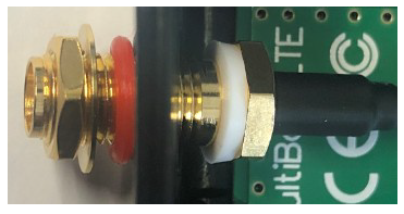
- Please see the picture below for reference on how to place rubber seals for best water protection;
- Reassembly in backorder. Tightening torque for PCB screws 0.3 Nm, case cover/enclosure screws 0.5 Nm.
After you have reinserted the device into the case and secured it with the screws that were removed earlier, slide in the SIM cards from your mobile operator into the SIM slots, with the chips facing as shown on the port label. The slot accepts miniSIM (2FF). SIM slots 2 and 3 apply to the bottom miniPCIe slot and can be switched in RouterOS “/system routerboard sim” menu.
- Hold this button during boot time until LED light starts flashing, release the button to resetRouterOS configuration (total 5 seconds).
- Keep holding for 5 more seconds, LED turns solid, release now to turn on CAP mode. The devicewill now look for a CAPsMAN server (total 10 seconds).
- Or keep holding the button for 5 more seconds until LED turns off, then release it to make theRouterBOARD look for Netinstall servers (total 15 seconds).
Regardless of the above option used, the system will load the backup RouterBOOT loader if the button is pressed before power is applied to the device. Useful for RouterBOOT debugging and recovery.
Accessories
Package includes accessories that come with the device:
- K-67 fastening set. Includes four screws 4×25 mm, four dowels 6×30 mm.
- Cable DC (H4130-04PDB000R 3 mm 2x2P Housing) to (StripJacket ⎓ 5 cm+WireEnd Strip/Tin 1 cm) 24 AWG (Black/Red/Blue/Orange) 0.35 m.
- EU/US Switching Power Supply 24 V, 1.2 A, 28.8 W, 86.8%, VI, DC ⎓ cable: 220 cm RA DC plug mod Hor CMC shorter plug.
Operating system support
The device supports RouterOS software version 6.47.6. The specific factory-installed version number is indicated in the RouterOS menu /system resource. Other operating systems have not been tested.
MikroTik mobile app
Use the MikroTik smartphone app to configure your router in the field, or to apply the most basic initial settings for your MikroTik home access point.

- Scan QR code and choose your preferred OS.
- Install and open application.
- By default, the IP address and user name will be already entered.
- Click Connect to establish a connection to your device through a wireless network.
- Choose Quick setup and application will guide you through all basic configuration settings in a couple of easy steps.
Safety Warnings
Before you work on any equipment, be aware of the hazards involved with electrical circuitry, and be familiar with standard practices for preventing accidents.
Read the installation instructions before connecting the system to the power source. This equipment is to be installed by trained and qualified personnel, as per these installation instructions. The installer is responsible for obtaining any required local or national safety inspections of the structural integrity of the installation by the local authority/inspection department.All installation methods for mounting an access point on any wall surface is subject to the acceptance of local jurisdiction.
The Installation of the equipment must comply with local and national electrical codes.This unit is intended to be mounted outdoors on a pole. Please read the mounting instructions carefully before beginning installation. Failure to use the correct hardware and configuration or to follow the correct procedures could result in a hazardous situation to people and damage to the system.
We cannot guarantee that no accidents or damage will occur due to the improper use of the device.Please use this product with care and operate at your own risk.
Notice
The Frequency band 5.470-5.725 GHz isn’t allowed for commercial use.
- In case WLAN devices work with different ranges than the above regulations, then a customized firmware version from the manufacturer/supplier is required to be applied to the end-user equipment and also prevent the end-user from reconfiguration.
- For Outdoor Usage: End-user requires approval/license from the NTRA.
- Datasheet for any device is available on the official manufacturer website.
- Products with the letters “EG” at the end of their serial number have their wireless frequency range limited to 2.400 – 2.4835 GHz, the TX power is limited to 20dBm (EIRP).
- Products with the letters “EG” at the end of their serial number have their wireless frequency range limited to 5.150 – 5.250 GHz, the TX power is limited to 23dBm (EIRP).
- Products with the letters “EG” at the end of their serial number have their wireless frequency rangelimited to 5.250 – 5.350 GHz, the TX power is limited to 20dBm (EIRP).
- Please make sure the device has a lock package (firmware version from the manufacturer) which is required to be applied to the end-user equipment to prevent the end-user from reconfiguration. The product will be marked with country code “-EG”. This device needs to be upgraded to the latest version to ensure compliance with local authority regulations! It is the end users responsibility to follow local country regulations, including operation within legal frequency channels, output power, cabling requirements, and Dynamic Frequency Selection (DFS) requirements. All MikroTik radio devices must be professionally installed.
CE Declaration of Conformity
References
LtAP kit-series – User manuals – MikroTik Documentation
MikroTik Routers and Wireless – Products
LtAP kit-series – User manuals – MikroTik Documentation
MikroTik Routers and Wireless – Products: LtAP LR8 LTE kit
Manual:System/GPS – MikroTik Wiki
MikroTik Routers and Wireless – Products: Antenna kit for LoRa®
Manual:Interface/Lora – MikroTik Wiki
[xyz-ips snippet=”download-snippet”]