![]() LDF LTE6 kitInstruction Manual
LDF LTE6 kitInstruction Manual
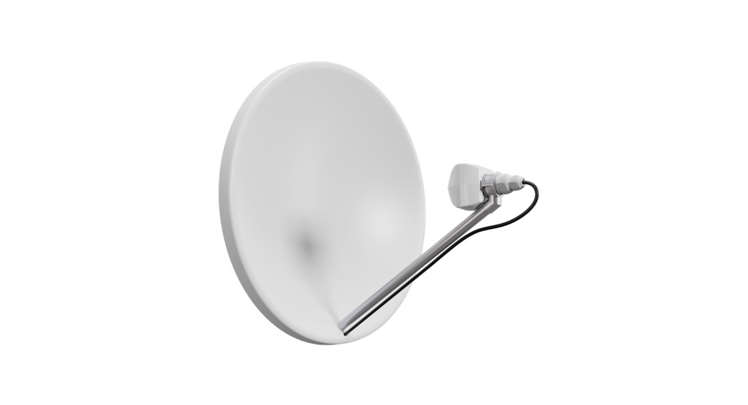
The LDF (Lite dish feed) is an outdoor LTE system, meant to be installed on an offset dish. The device comes with a modem and is ready to use.
Safety WarningsBefore you work on any equipment, be aware of the hazards involved with electrical circuitry and be familiar with standard practices for preventing accidents.Ultimate disposal of this product should be handled according to all national laws and regulations.The Installation of the equipment must comply with local and national electrical codes.This unit is intended to be mounted on a pole. Please read the wall mounting instructions carefully before beginning installation. Failure to use the correct hardware or to follow the correct procedures could result in a hazardous situation to people and damage to the system.Read the installation instructions before connecting the system to the power source.
![]() It is the customer’s responsibility to follow local country regulations, including operation within legal frequency channels, output power, cabling requirements, and Dynamic Frequency Selection (DFS) requirements. All Mikrotik radio devices must be professionally installed.
It is the customer’s responsibility to follow local country regulations, including operation within legal frequency channels, output power, cabling requirements, and Dynamic Frequency Selection (DFS) requirements. All Mikrotik radio devices must be professionally installed.
Quick start
- Insert SIM card, chip facing UP towards Ethernet port.
- Connect an Ethernet cable to the Ethernet port, connect the other end of the Ethernet cable to a PoE injector. Plug the PoE injector into your PC or into your local network switch. Plug the power adapter into the PoE injector to start your device.
- On your local network, open http://192.168.88.1 in your web browser to start configuration, since there is no password by default, you will be logged in automatically.
- Click the “Check for updates” button and update your RouterOS software to the latest version to ensure the best performance and stability.
- After an update please login again and set up your password.
PoweringThe device accepts 10-28 V DC input from passive Power over Ethernet injectors. The device does not work with IEEE802.3af compliant 48 V power injectors. A PoE injector is included in the package. Maximum power consumption 8 W.Connecting to a PoE Adapter:
- Connect the Ethernet cable from the device to the PoE+DATA port of the PoE adapter.
- Connect an Ethernet cable from your local network (LAN) to the PoE adapter.
- Connect the power cord to the adapter, and then plug the power cord into a power outlet.
Assembly
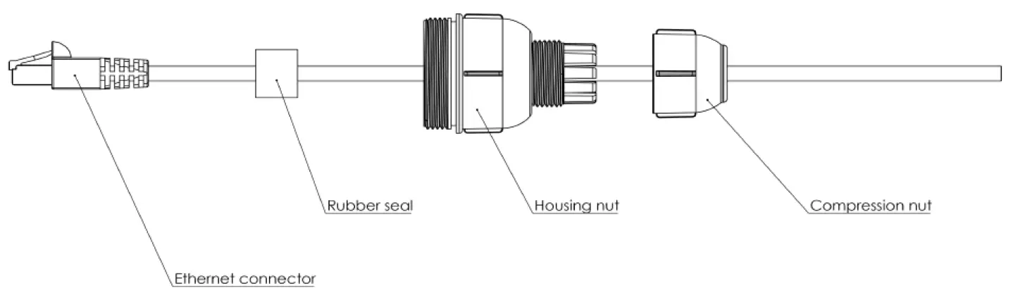
The device is compatible with standard offset dishes. Assemble Ethernet cable with cover as shown on the illustration:
- A rubber seal has been cut on the side so you can attach it to the Ethernet cable. It needs to be inside the Housing nut when assembling the compression nut will compress it to the Ethernet cable.

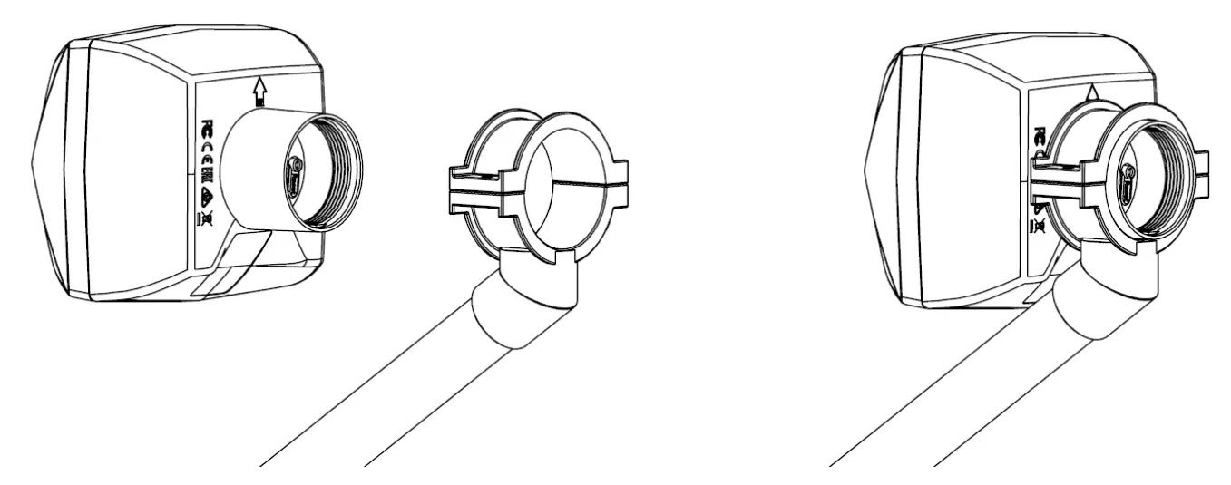
- Attach the unit to your dish, LDF mounting diameter is 40 mm. Please, ensure to placement with an arrow facing upwards.
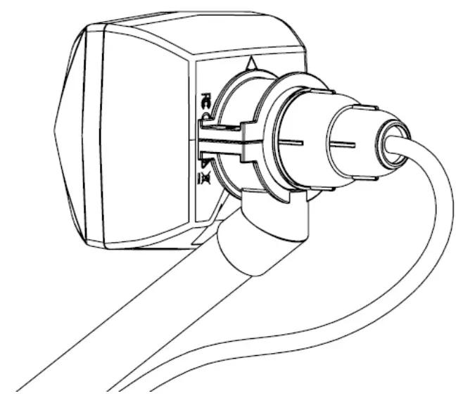
- Plugin Ethernet cable and tighten the cover by screwing it clockwise.
Mounting
The device is designed to be used outdoors and mounted on the dish, with Ethernet cable connecting to the back of the unit.Please ensure to mount the LDF unit on the offset mount in the proper position – unit facing upwards to the dish.The dish will act as a reflector, amplifying the signal. The final position of your assembly should be placed and installed on the pole. For pole mounting instructions please refer to your dish mounting instructions.![]() Please ensure that cable feed is pointing downwards.The IPX rating scale of this device is IP54. We recommend using Cat6 shielded cables.Warning! This equipment should be installed and operated with a minimum distance of 20 cm between the device and your body. Operation of this equipment in the residential environment could cause radio interference.Mounting and configuration of this device should be done by a qualified person.
Please ensure that cable feed is pointing downwards.The IPX rating scale of this device is IP54. We recommend using Cat6 shielded cables.Warning! This equipment should be installed and operated with a minimum distance of 20 cm between the device and your body. Operation of this equipment in the residential environment could cause radio interference.Mounting and configuration of this device should be done by a qualified person.
Extension slots and ports
- One Ethernet port, supporting automatic cross/straight cable correction (Auto MDI/X), so you can use either straight or cross-over cables for connecting to other network devices.
- MiniPCIe slot with an integrated modem.
- Mode button.
The reset button has three functions:
- Hold this button during boot time until LED light starts flashing, release the button to reset RouterOS configuration (total 5 seconds).
- Keep holding for 5 more seconds, LED turns solid, release now to turn on CAP mode. The device will now look for a CAPsMAN server (total 10 seconds).
- Or Keep holding the button for 5 more seconds until LED turns off, then release it to make the RouterBOARD look for Netinstall servers (total 15 seconds).Regardless of the above option used, the system will load the backup RouterBOOT loader if the button is pressed before power is applied to the device. Useful for RouterBOOT debugging and recovery.
Operating system support
The device supports RouterOS software version 6.46. The specific factory installed version number is indicated in the RouterOS menu /system resource. Other operating systems have not been tested.
 Federal Communication Commission Interference Statement
Contains FCC ID: TV7R11ELTE6This equipment has been tested and found to comply with the limits for a Class B digital device, pursuant to Part 15 of the FCC Rules. These limits are designed to provide reasonable protection against harmful interference in a residential installation.This equipment generates, uses and can radiate radio frequency energy and, if not installed and used in accordance with the instructions, may cause harmful interference to radio communications. However, there is no guarantee that interference will not occur in a particular installation. If this equipment does cause harmful interference to radio or television reception, which can be determined by turning the equipment off and on, the user is encouraged to try to correct the interference by one of the following measures:
- Reorient or relocate the receiving antenna.
- Increase the separation between the equipment and receiver.
- Connect the equipment into an outlet on a circuit different from that to which the receiver is connected.
- Consult the dealer or an experienced radio/TV technician for help.
FCC Caution: Any changes or modifications not expressly approved by the party responsible for compliance could void the user’s authority to operate this equipment.This device complies with Part 15 of the FCC Rules. Operation is subject to the following two conditions: (1) This device may not cause harmful interference, and (2) this device must accept any interference received, including interference that may cause undesired operation. This device and its antenna must not be co-located or operation in conjunction with any other antenna or transmitter.IMPORTANT: Exposure to Radio Frequency Radiation.This equipment complies with the FCC RF radiation exposure limits set forth for an uncontrolled environment. This equipment should be installed and operated with a minimum distance of 20 cm between the radiator and any part of your body.For use of CBRS bands, the CBSD Category of the final Host equipment will be dependent on the power settings and antenna gain used.
Innovation, Science and Economic Development CanadaThis device contains licence-exempt transmitter(s)/receiver(s) that comply with Innovation, Science and EconomicDevelopment Canada’s licence-exempt RSS(s). Operation is subject to the following two conditions:
- This device may not cause interference;
- This device must accept any interference, including interference that may cause undesired operation of the device.
IMPORTANT: Exposure to Radio Frequency Radiation.This equipment complies with the IC radiation exposure limits set forth for an uncontrolled environment. This equipment should be installed and operated with a minimum distance of 20 cm between the radiator and any part of your body.
The device for operation in the band 5150–5250 MHz is only for indoor use to reduce the potential for harmful interference to co-channel mobile satellite systems.
CE Declaration of Conformity Manufacturer: Mikrotikls SIA, Brivibas gatve 214i Riga, Latvia, LV1039.
Hereby, Mikrotīkls SIA declares that the radio equipment type RouterBOARD is in compliance with Directive 2014/53/EU. The full text of the EU declaration of conformity is available at the following internet address: https://mikrotik.com/products
MPE statement
This equipment complies with EU radiation exposure limits set forth for an uncontrolled environment. This equipment should be installed and operated with minimum distance of 20 cm between the radiator and your body, unless specifically stated otherwise in page 1 of this document.In RouterOS you must specify your country, to make sure local wireless regulations are observed. This device meets Maximum 2G/3G/4G LTE per ETSI regulations.
Frequency bands terms of use
| Frequency range (for applicable models) | Channels used | Maximum Output Power (EIRP) | Restriction |
| 2412-2472 MHz | 1 – 13 | 20 dBm | Without any restriction to use in all EU Member States |
| 5150-5250 MHz | 26 – 48 | 23 dBm | Restricted to indoor use only* |
| 5250-5350 MHz | 52 – 64 | 20 dBm | Restricted to indoor use only* |
| 5470-5725 MHz | 100 – 140 | 27 dBm | Without any restriction to use in all EU Member States |
 * It is the customer’s responsibility to follow local country regulations, including operation within legal frequency channels, output power, cabling requirements, and Dynamic Frequency Selection (DFS) requirements. All MikroTik radio devices must be professionally installed!According to Commission Decision 2000/299/EC (6 April 2000), the product falls under the scope of Class 2.Note. Information contained here is subject to change. Please visit the product page on www.mikrotik.com for the most up to date version of this document.

 report this ad
Instruction manual: Connect the power adapter to turn on the device. Open 192.168.88.1 in your web browser, to configure it. More information on https://mt.lv/help
See mikrotik.com/products for the latest version of this document.Document #54165 Modified on: 07.JAN.2020
References
[xyz-ips snippet=”download-snippet”]