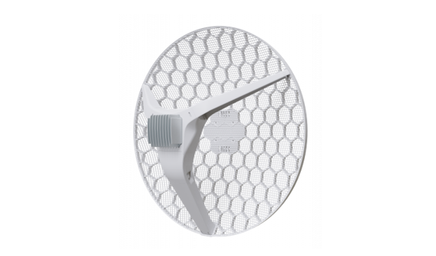
LHGG LTE6 kit (RBLHGGR&R11e-LTE6)
Quickstart
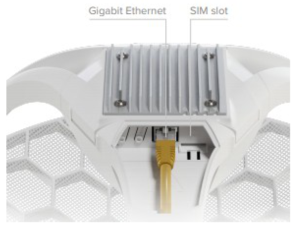
- Open the Ethernet port door;
- Insert the SIM card into the slot, with the chip facing UP;
- Connect the device to the included PoE injector with Ethernet cable to the data+power end;
- Connect the data end of the PoE injector into the computer;
- Connect the power adapter to the PoE injector;
- Open the https://192.168.88.1 in your web browser;
- User name: admin, and there is no password;
- Enter the PIN code, if required by your mobile network operator;
- Use the check for update option to upgrade the device to the latest version. You must have an active SIM card with available data;
- The device will reboot;
- Connect again and in the QuickSet menu set a strong password.
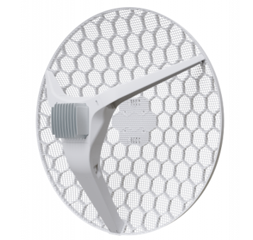
Case assembly
1. Attach the two legs to the LHG case by sliding them onto the respective sides, legs are different and cannot be exchanged (when looking at the product place it that cover for Ethernet port is in front of you, leg marked R is for the right side, leg marked L is for the left side).2. Snap the assembled LHG unit to the grid in the appropriate central location.3. Fix the two legs in place with included two self thread screws (Phillips screwdriver PH2). The package also contains a grounding cable connector and a 5- degree angle adapter, for easier up or downward tilt adjustment.
Opening the case cover
Optional – to access the mini PCIe slot, the opening of the unit top cover is required. As an opening tool, you can use a large-size flat head screwdriver or a small coin. Be extremely cautious when opening, because the incorrect opening of the clip can break it off! The mounting and configuration of this device should be done by a qualified person. Follow these steps:
1. Follow this order when opening the unit.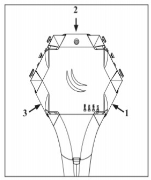 2. Insert a screwdriver into the first slot.
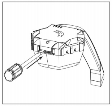 3. Turn the screwdriver, until one side pops open. Continue in the above order.
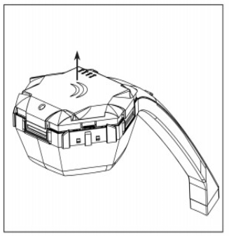
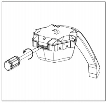 4. Lift cover to access the card.
Additional Caution when lifting up the cover, do not force it with sharp objects.miniPCIe slot usageThe device is equipped with a miniPCIe slot and has already installed an LTE6 modem. One SIM slot is provided for use together with a miniPCIe modem. The SIM slot is not used separately. Replacing a miniPCIe module should be done by a qualified person, please follow safety precautions when handling electrical equipment:
1. Use a wrist grounding strap when unpacking and working with electrical components to avoid electrical discharge (ESD) damage;2. Open the upper cover as shown in instruction previously;
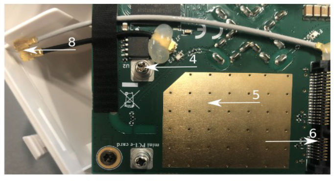
3. The antenna is located underneath PCB;4. Locate the miniPCIe slot on the PCB and remove two factory attached screws;5. Attach provided a thick thermal pad to the card, and install the card into miniPCIe slot so that thermal pad is between PCB and card;6. Insert your desired card;7. The secure card in place using previously removed two screws;8. Attach the grey uFL connector to the MAIN antenna connector of the modem, attach the black cable to the secondary (or AUX) connector;9. Attach a thinner thermal pad to the top of the card;10.Reassemble.
After reassembly, slide in the SIM card from your mobile operator into the SIM slot, with the chips facing up as shown on the port label. The slot accepts MicroSIM (3FF).
Powering
The device can be powered from 12-57 V 802.3af/at sources and also Passive PoE injectors (one power supply and PoE injector are included). Maximum power consumption 6 W. Connecting to a PoE Adapter:
1. Connect the Ethernet cable from the device to the PoE+DATA port of the PoE adapter;2. Connect an Ethernet cable from your local network (LAN) to the PoE adapter;3. Connect the power cord to the adapter, and then plug the power cord into a power outlet.
Mounting
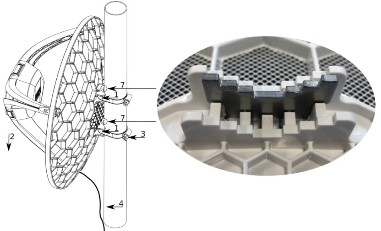
1. Slide the included metallic mounting rings into the two slots on the back of the antenna dish.2. Attach the unit to a pole, with the Ethernet port pointing downward.3. Use a PH2 screwdriver to tighten the rings.4. Fix the Ethernet cable to the pole using zip ties, less than one meter from the unit, to avoid the cable being pulled out of the port.5. Check mounting angle and positioning.6. Optional: If required, before mounting the unit, you can insert the included 5-degree adjustment adapter into the top or bottom slot where the mounting ring is inserted. This will create an additional upward or downward angle when the unit is tightened to a vertical pole.7. Insert a 5-degree angle adapter to one of the slots and remount the unit.When mounting outdoors, please ensure that any cable openings are directed downwards. Use POE injector and proper grounding, this device has a specially designed grounding connector under the port cover. Recommended using shielded Cat5/6 cable. The IP rating scale for this device is IP54. Warning! This equipment should be installed and operated with a minimum distance of 120 cm between the device and your body. The operation of this equipment in the residential environment could cause radio interference.
Configuration
Once logged in, we recommend clicking the “Check for updates” button in the QuickSet menu, as updating your RouterOS software to the latest version ensures the best performance and stability. For wireless models, please make sure you have selected the country where the device will be used, to conform with local regulations.RouterOS includes many configuration options in addition to what is described in this document. We suggest starting here to get yourself accustomed to the possibilities: https://mt.lv/help. In case IP connection is not available, the Winbox tool (https://mt.lv/winbox) can be used to connect to the MAC address of the device from the LAN side (all access is blocked from the Internet port by default).
Accessories
The package includes the following accessories and parts that come with the device:
- ADAPT1_ EU/US Switching Power Supply 24V, 0.8A;
- CLAMP1,2_ Hose Clamp SUS304 (philips type; 9mm; clamping diameter range 25-70mm) with EPE bag;
- POE1_ Gigabit POE injector;
- K-SET_K_Set for LHGGR&R11e-LTE6;
- CASE1_ LHG-LTE-RHLEG-R0;
- CASE2_ LHG-LTE-LHLEG-R0;
- CASE10_ LHG-5G-390mm Dish 3,0×2.5×0,5mm;
- Assembled LHGGR main leg.
Expansion slots and ports
- One Gigabit Ethernet port, supporting automatic cross/straight cable correction (Auto MDI/X). Either straight or crossover cable can be used for connecting to other network devices. The Ethernet port accepts 9-30 V DC powering from a passive PoE injector.
- MiniPCIe slot with LTE6 modem.
- SIM slot (can’t be used separately).
The reset button has three functions:
- Hold this button during boot time until LED light starts flashing, release the button to reset RouterOS configuration (total 5 seconds);
- Keep holding for 5 more seconds, LED turns solid, release now to turn on CAP mode. The device will now look for a CAPsMAN server (total 10 seconds);
- Or Keep holding the button for 5 more seconds until LED turns off, then release it to make the RouterBOARD look for Netinstall servers (total 15 seconds);Regardless of the above option used, the system will load the backup RouterBOOT loader if the button is pressed before power is applied to the device. Useful for RouterBOOT debugging and recovery.
The action of the mode buttons can be configured from RouterOS software to execute any user-supplied RouterOS script. You can also disable this button. The mode button can be configured in the RouterOS menu /system routerboard mode-button.
Operating system support
The device supports RouterOS software version 6.46. The specific factory-installed version number is indicated in the RouterOS menu /system resource. Other operating systems have not been tested.
Safety Notice
![]()
Electric shock hazard. This equipment is to be serviced by trained personnel only. This is a class A device, operating it near residential radio equipment could cause radio interference.Federal Communication Commission Interference Statement
| Model | Contains FCC ID |
| RBLHGGR&R11eLTE6 | TV7R11ELTE6 |
![]()
This equipment has been tested and found to comply with the limits for a Class A digital device, pursuant to Part 15 of the FCC Rules. These limits are designed to provide reasonable protection against harmful interference in a commercial installation.This equipment generates, uses, and can radiate radio frequency energy and, if not installed and used in accordance with the instruction manual, may cause harmful interference to radio communications.Operation of this equipment in a residential area is likely to cause harmful interference in which case the user will be required to correct the interference at his own expense.FCC Caution: Any changes or modifications not expressly approved by the party responsible for compliance could void the user’s authority to operate this equipment.This device complies with Part 15 of the FCC Rules. Operation is subject to the following two conditions:(1) This device may not cause harmful interference, and (2) this device must accept any interference received, including interference that may cause undesired operation.Note: This unit was tested with shielded cables on the peripheral devices. Shielded cables must be used with the unit to ensure compliance.
Innovation, Science and Economic Development Canada
| Model | Contains IC |
| RBLHGGR&R11eLTE6 | 7442AR11ELTE6 |
This device contains license-exempt transmitter(s)/receiver(s) that comply with Innovation, Science, and Economic Development Canada’s license-exempt RSS(s). Operation is subject to the following two conditions: (1) This device may not cause interference. (2) This device must accept any interference, including interference that may cause undesired operation of the device.This Class A digital apparatus complies with Canadian ICES-003.
This MikroTik device meets Maximum TX power limits per ETSI regulations. For more detailed information see the Declaration of Conformity above
References
[xyz-ips snippet=”download-snippet”]