
LtAP mini LTE kit
The LtAP mini LTE is a wireless access point with two SIM card slots for 3G/LTE data. The LtAP mini LTE comes with factory installed LTE card.
Connecting
![]() Choose your powering solution, please see Powering section for possibilities.
Choose your powering solution, please see Powering section for possibilities.![]() Connect your Internet cable to the Ethernet port.
Connect your Internet cable to the Ethernet port.![]() Set your computer IP configuration to automatic (DHCP).
Set your computer IP configuration to automatic (DHCP).![]() Connect your direct input power jack if not using POE, to start up the device.
Connect your direct input power jack if not using POE, to start up the device.![]() The device will boot up and after short beep Wireless network will be available for connecting.
The device will boot up and after short beep Wireless network will be available for connecting.![]() Open network connections on your pc, mobile phone or other device and search for MikroTik wireless network and connect to it.
Open network connections on your pc, mobile phone or other device and search for MikroTik wireless network and connect to it.![]() Once connected to the wireless network, open http://192.168.88.1 in your web browser to start configuration, since there is no password by default, you will be logged in automatically.
Once connected to the wireless network, open http://192.168.88.1 in your web browser to start configuration, since there is no password by default, you will be logged in automatically.![]() We recommend clicking the “Check for updates” button and updating your RouterOS software to the latest version to ensure the best performance and stability,
We recommend clicking the “Check for updates” button and updating your RouterOS software to the latest version to ensure the best performance and stability,![]() Choose your country, to apply country regulation settings and set up your password in the screen that loads.
Choose your country, to apply country regulation settings and set up your password in the screen that loads.
Mounting
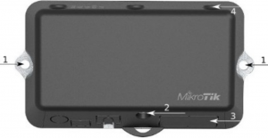
- It is possible to attach the device to a wall, using the provided screw holes on the sides of the unit. The device should be mounted in a way that the cable openings are pointing downward as shown on the picture.
- The ports are protected with a small door, that is held in place with one screw. Use Philips PH2 screwdriver to access the ports.
- The door has cut-out places for all available ports, but please only break out the openings that you will use. The device can be used both indoors and outdoors. The IP rating scale for this device is IP54.
- The device enclosure has places where you can drill openings for external LTE and GPS antennas. Use a drill to make holes that are appropriate for the antenna cable used.
When mounting outdoors, please ensure that any cable openings is directed downwards. Use POE injector and proper grounding. Recommended using Cat5/6 cable.
Warning! This equipment should be installed and operated with a minimum distance of 20 cm between the device and your body. Operation of this equipment in the residential environment could cause radio interference.
Mounting and configuration of this device should be done by a qualified person.
Powering
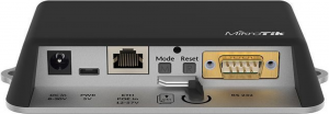
- Direct-input power jack (5.5 mm outside and 2 mm inside, female, pin positive plug) accepts 8-30 V DC.
- microUSB port accepts 5 V powering.
- Ethernet port accepts passive and 802.3af/at Power over Ethernet 8-57 V DC (compensate for loss on cable, so more than 12 V recommended).
The power consumption under maximum load with attachments can reach 9 W.
Connecting to a POE Adapter:
- Connect the Ethernet cable from the device to the POE port of the POE adapter.
- Connect an Ethernet cable from your LAN to the LAN port of the POE adapter, please mind arrows for data and power flow.
- Connect the power cord to the adapter, and then plug the power cord into a power outlet.
Extension slots and ports
- Built-in 2 GHz wireless access point module, AP/station/bridge/p2p modes are supported. Onboard PIF antennas built in. Antenna gain1.5 dBi.
- miniPCIe slot and two SIM slots (can’t be used without a modem installed, can’t be used both at the same time) to be used with a 3G/4G/LTE modem. Onboard antennas available, but openings for external antennas are provided on the case.
- Built-in GPS module with a built in antenna. One uFL connector provided for an optional external antenna. To enable, set the port to serial0 (this disables the DB9 port on the unit).
- One 10/100 Ethernet port, supporting automatic cross/straight cable correction (Auto MDI/X). Either straight or crossover cable can be used for connecting to other network devices. The Ethernet port accepts 12-57 V DC powering from a passive PoE injector.
- One DB9 RS232 serial port for serial console access. Configured as 115200 bit/s, 8 data bits, 1 stop bit, no parity. Can’t be used if built-in GPS is enabled on serial0.
- One microUSB 2.0 port for powering only.
Configuration
RouterOS includes many configuration options in addition to what is described in this document. We suggest to start here to get yourself accustomed to the possibilities: http://mt.lv/help. In case IP connection is not available, the Winbox tool (http://mt.lv/winbox) can be used to connect to the MAC address of the device from the LAN side (all access is blocked from the internet port by default).
For recovery purposes, it is possible boot the device from network, see section Buttons and jumpers.
miniPCIe slot
The device is equipped with a miniPCIe slot to be used with a 3G/4G/LTE modem. Two SIM slots are provided for use together with a miniPCIe modem. SIM slot is not usable separately.
In this case, an internal antenna is connected to the LTE installed card (located inside the enclosure).
Optional, replacing a miniPCIe module should be done by a qualified person, please follow safety precautions when handling electrical equipment:
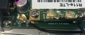
1. use a wrist grounding strap when unpacking and working with electrical components to avoid electrical discharge (ESD) damage,2. open front cover by unscrewing one screw with Philips PH2 screwdriver,3. remove four screws on the bottom of the case and lift off the top part of the case. You will see the antenna attached to it,4. locate the miniPCIe slot on the PCB and remove two factory attached screws,5. attach provided a thick thermal pad to the card, and install the card into miniPCIe slot so that thermal pad is between PCB and card,6. secure card in place using previously removed two screws,7. attach the grey uFL connector to the MAIN antenna connector of the modem, attach the black cable to the secondary (or AUX) connector,8. it is possible to use external antennas, to attach antenna connector use 6.5 mm drill bit to drill holes on the side of the unit,9. please see picture bellow on how to place rubber seals for best water protection,
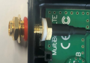
10. attach antenna connectors to the installed card and GPS, as additional rubber silicone can be used to secure connectors in place on card and PCB board,
11. attach a thinner thermal pad to the top of the card,12. reassembly in back order.
After you have reinserted the device into the case and secured it with the screws that were removed earlier, slide in the SIM cards from your mobile operator into the SIM slots, with the chips facing as shown on the port label. The slot accepts miniSIM (2FF). Close the black latch for SIM cards, to secure them in the slots.
- Hold this button during boot time until LED light starts flashing, release the button to reset RouterOS configuration (total 5 seconds).
- Keep holding for 5 more seconds, LED turns solid, release now to turn on CAP mode. The device will now look for a CAPsMAN server (total 10 seconds).
- Or keep holding the button for 5 more seconds until until LED turns off, then release it to make the RouterBOARD look for Netinstall servers (total 15 seconds).
Regardless of the above option used, the system will load the backup RouterBOOT loader if the button is pressed before power is applied to the device. Useful for RouterBOOT debugging and recovery.
Mode buttonThe action of the mode buttons can be configured from RouterOS software to execute any user supplied RouterOS script. You can also disable this button. The mode button can be configured in RouterOS menu /system routerboard mode-button
Accessories
Package includes following accessories that comes with the device:
- DC
 Switching Power Supply 24 V, 1.2 A, 28.8 W, 86.8 %, VI, cable:220 cm RA DC.
 - Cable DC plug RA 5.5×2.1×10.5 to Striped 2*24 AWG Tin 8 mm, legth 0.35 m.
- POE Injector with shielded Ethernet cable/connector (RBPOE).
- Mounting kit K-55 vms.
Specifications
For more information about this product, specification and pictures please visit our web page: https://mikrotik.com/product/ltap_mini_lte_kit
Operating system support
The device supports RouterOS software version 6. The specific factory installed version number is indicated in the RouterOS menu /system resource. Other operating systems have not been tested.

Federal Communication Commission Interference Statement
FCC ID:TV7RB912R-2NDLTM
This equipment has been tested and found to comply with the limits for a Class B digital device, pursuant to Part 15 of the FCC Rules. These limits are designed to provide reasonable protection against harmful interference in a residential installation.
This equipment generates, uses and can radiate radio frequency energy and, if not installed and used in accordance with the instructions, may cause harmful interference to radio communications. However, there is no guarantee that interference will not occur in a particular installation. If this equipment does cause harmful interference to radio or television reception, which can be determined by turning the equipment off and on, the user is encouraged to try to correct the interference by one of the following measures:
- Reorient or relocate the receiving antenna.
- Increase the separation between the equipment and receiver.
- Connect the equipment into an outlet on a circuit different from that to which the receiver is connected.
- Consult the dealer or an experienced radio/TV technician for help.
FCC Caution: Any changes or modifications not expressly approved by the party responsible for compliance could void the user’s authority to operate this equipment.
This device complies with Part 15 of the FCC Rules. Operation is subject to the following two conditions: (1) This device may not cause harmful interference, and (2) this device must accept any interference received, including interference that may cause undesired operation. This device and its antenna must not be co-located or operation in conjunction with any other antenna or transmitter.
Contains FCC ID: TV7R11ELTE
IMPORTANT: Exposure to Radio Frequency Radiation.This equipment complies with the FCC RF radiation exposure limits set forth for an uncontrolled environment. This equipment should be installed and operated with a minimum distance of 20 cm between the radiator and any part of your body.For use of CBRS bands, the CBSD Category of the final Host equipment will be dependent on the power settings and antenna gain used.
Industry Canada
IC:7442A-912R2NDLTM
This device complies with Industry Canada licence-exempt RSS standard(s). Operation is subject to the following two conditions: (1) this device may not cause interference, and (2) this device must accept any interference, including interference that may cause undesired operation of the device.
Contains IC: 7442A-R11ELTE
IMPORTANT: Exposure to Radio Frequency Radiation.
This equipment complies with the IC radiation exposure limits set forth for an uncontrolled environment. This equipment should be installed and operated with a minimum distance of 20 cm between the radiator and any part of your body.
CAN ICES-3 (B)/NMB-3(B)
CE Declaration of Conformity ![]()
Manufacturer: Mikrotikls SIA, Brivibas gatve 214i Riga, Latvia, LV1039.
Hereby, Mikrotkls SIA declares that the radio equipment type RouterBOARD is in compliance with Directive 2014/53/EU. The full text of the EU declaration of conformity is available at the following internet address: https://mikrotik.com/products
MPE statementThis equipment complies with EU radiation exposure limits set forth for an uncontrolled environment. This equipment should be installed and operated with minimum distance of 20 cm between the radiator and your body, unless specifically stated otherwise in page 1 of this document. In RouterOS you must specify your country, to make sure local wireless regulations are observed.
This device meets Maximum 2G/3G/4G LTE per ETSI regulations.
Frequency bands terms of use
| Frequency range (for applicable models) | Channels used | Maximum Output Power (EIRP) | Restriction |
| 2412-2472 MHz | 1 – 13 | 20 dBm | Without any restriction to use in all EU Member States |
| 5150-5250 MHz | 26 – 48 | 23 dBm | Restricted to indoor use only* |
| 5250-5350 MHz | 52 – 64 | 20 dBm | Restricted to indoor use only* |
| 5470-5725 MHz | 100 – 140 | 27 dBm | Without any restriction to use in all EU Member States |

* It is the customer’s responsibility to follow local country regulations, including operation within legal frequency channels, output power, cabling requirements, and Dynamic Frequency Selection (DFS) requirements. All Mikrotik radio devices must be professionally installed!
According to Commission Decision 2000/299/EC (6 April 2000), the product falls under the scope of Class 2.Note. Information contained here is subject to change. Please visit the product page on www.mikrotik.com for the most up to date version of this document.

Instruction manual: Connect the power adapter to turn on the device. Open 192.168.88.1 in your web browser, to configure it. More information on http://mt.lv/help
References
[xyz-ips snippet=”download-snippet”]