
![]()
496 3/4 inch Miller Grip Anchorage Connector Instruction Manual
Model #496
IMPORTANT!!All persons using this equipment must read, understand and follow all instructions. Failure to do so may result in serious injury or death. Users should be familiar with pertinent regulations governing this equipment. All individuals who use this product must be properly trained in its use. If a fall occurs, the Miller Grip must be disposed of according to the manufacturer’s instructions.
- The Miller Grip Anchorage Connector Model #496 is designed for:
- single-user fall protection applications, work positioning and restraint
- concrete use only in horizontal, vertical or overhead/ceiling surfaces
Specifications

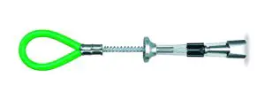
For use by ONE PERSON ONLYColor Coded with Bright Green Tubing to Indicate “FALL PROTECTION USE ONLY”For use in CONCRETE ONLY
Materials

MADE IN THE USA
WARNING!!
- All warnings and instructions shall be provided to authorized persons/users.
- Proper precautions should always be taken to remove any obstructions, debris, material, or other recognized hazards from the work area that could cause injuries or interfere with the operation of the system.
- Always inspect unit according to manufacturer’s instructions prior to each use. Do not use this device if any components are damaged, cracked, broken, or deformed. Do not use the device if it does not operate smoothly and properly.
- All equipment should be inspected by a qualified person on a regular basis.
- To minimize the potential for accidental disengagement, a competent person must ensure system compatibility.
- Fall arrest systems used with the anchorage connector must be rigged in accordance to regulatory requirements. (All instructions and warnings provided with the components of the personal fall arrest system must be read, understood, and followed.)
- Ensure that the anchor point, in combination with the connecting device, is at a height that limits free fall distance to 6 feet (1.8m) or less.
WARNING!!
- Use the proper method of coupling to anchorage.
- Do not use incompatible connectors with this device. Use only Miller approved connectors/connecting devices, such as auto-locking snap hooks and carabiners. Always ensure that connectors are fully closed and locked when in use. (Refer to separate instructions supplied with the connecting device.)
- Always work directly under the anchor point to avoid a swing-fall injury.
- Always check for obstructions below the work area to make sure potential fall path is clear and allow adequate fall clearance below the work surface.
- The authorized person/user shall have a rescue plan and the means at hand to implement it when using this equipment.
- Remove unit from service if subjected to fall arrest forces. This product is not designed to be repaired or altered in any way.
- Never use fall protection equipment for purposes other than those for which it was designed.
- Equipment must not be exposed to environmental hazards and chemicals which may produce a harmful effect.
- Do not allow equipment to come in contact with anything that will damage it, including, but not limited to, sharp, abrasive, rough or high-temperature surfaces, welding, heat sources, electrical hazards, or moving machinery.
- Do not expose the equipment to any hazard which it is not designed to withstand. Consult the manufacturer in cases of doubt.
- Pregnant women and minors must not use this product.
Installation and Use of Miller Grip Model 496
Miller Grip Model #496 is designed to be used for fall protection applications, work positioning and restraint. It is not to be used in any other anchoring situation. Only trained and competent personnel should install and use this equipment.
The device must be anchored in concrete substrate only. DO NOT use in steel, wood or any other substrate. Concrete must have a compressive strength of at least 3,000 PSI (20.7MPa). Do not anchor in uncured/wet concrete.
The device may be installed in horizontal, vertical or overhead/ceiling surfaces. Note: For horizontal surface applications, the Grip anchor must not be exposed to a greater than 90° bend.
The structure or substrate that this product is anchored to must be capable of supporting 5,000 lbs. (22.2 kN) per user attached; or be designed, installed and used, under the supervision of a qualified person, as part of a complete personal fall arrest system which maintains a safety factor of at least two.
Anchorage requirements based on ANSI are as follows:
- For fall arrest systems, anchorages must withstand a static load of 5,000 lbs. (22.2kN) for non-certified anchorages or two times the maxi mum arresting force for certified anchorages.
- For positioning systems, anchorages must withstand a static load of 3,000 lbs. (13.3kN) for non-certified anchorages or two times the foreseeable force for certified anchorages.
- For travel restraint, anchorages must withstand a static load of 1,000 lbs. (4.5kN) for non-certified anchorages or two times the foresee able force for certified anchorages.
- When more than one personal fall arrest system is attached to an anchorage, the above anchorage strengths must be multiplied by the number of personal fall arrest systems attached to the anchorage.
The Miller Grip Anchorage Connector is designed for use with Miller approved components. Substitution or replacement with non-approved component combinations or subsystems or both may affect or interfere with the safe function of each other and endanger the compatibility within the system. This incompatibility may affect the reliability and safety of the total system.
- Drill a 3/4” diameter hole at least 3” deep.
- Drill hole straight into substrate.
- Never drill hole closer than 6” to any edge or corner.
- Blow hole clean with compressed air.
- When reusing a previously drilled hole, always inspect the hole carefully. The previously drilled hole must be free of deformation. Drill another proper hole if needed.
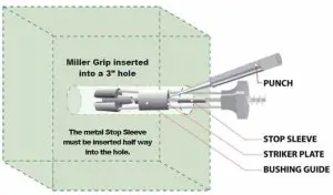
- Insert unit 3 inches deep into hole.
- Set the device with a slight tug on the anchor loop.
- The Stop Sleeve must always be partially inserted into the hole.
- Remove device at the end of each day. Never leave inserted in a hole overnight.
- Inspect the anchorage connector for damage each time you use it. If damage has occurred, dispose of device properly.
- Never rely on a unit placed by unqualified workers.
Do not drill a hole closer than 6” from any edge or corner.
- If a hole is 6” from an edge or corner, the concrete substrate must be 12” thick and 12” wide (example – a 12” x 12” column).
- If a hole is 8” from an edge or corner, the concrete substrate must be 10” thick and 16” wide (example – a 10” x 16” column).
- If a hole is 10” from an edge or corner, the concrete substrate must be 8” thick and 20” wide (example – a 8” x 20” column).
- If a hole is 12” or more from any edge or corner, the concrete substrate must be 5” thick.
It is important that you drill your Miller Grip anchor hole to the manufacturer’s required depth and hole structure. All holes must be 3/4” in diameter and drilled at least 3” deep into the concrete substrate.
The bored hole walls must be straight and parallel. The bored hole must be of uniform diameter and free of peaks and valleys on the inner wall surfaces. Use only quality industrial grade rotary hammer drills and rotary hammer drill bits. NEVER USE A BENT DRILL BIT! DO NOT USE masonry drill bits.
Drill a straight 3/4” diameter hole at least 3” deep into concrete substrate with a rotary hammer drill that uses industrial grade SDS bits.
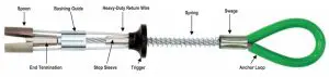
When placing a Miller Grip anchor, place your thumb inside the anchor loop and your first two fingers around the trigger. Retract the trigger until the spring bottoms out. With your hand, pinch the two spoons between your thumb and index finger. Hold the trigger fully retracted while inserting the unit into the bottom of the hole.
If a Miller Grip anchor becomes stuck, insert a punch, screwdriver or pointed object into the hole until the tip rests on the striker plate. Give a LIGHT, blunt tap with a hammer or heavy object. The striker plate will be easily visible at the edge of the hole.
Connecting devices used in conjunction with the Miller Grip Anchorage Connector must be attached to the anchor loop only.
Inspection:
- Make sure unit is straight and operates smoothly.
- Make sure the label is affixed to unit.
- Make sure trigger stop is not bent or damaged.
- Make sure cables are not kinked, frayed or damaged.
- Make sure metal components are not damaged.
- Make sure metal spoons and conical end fitting operate smoothly and no metal burrs have occurred.
- When reusing a previously drilled hole, always inspect the hole carefully.
Storage and Cleaning:
- Blow off unit after each use with compressed air.
- Store in clean dry environment.
- Store in secure locked area.
- Store and put away at the end of each work day.
- Do not pile any objects on top of unit during storage.
- Keep unit free of grease, oils and dirt.
- Never lend your unit to other workers.
Disposal:
- Dispose of unit after any fall has occurred.
- Dispose of unit if cable becomes kinked or bent.
- Dispose of unit if trigger stop is bent or damaged.
- Dispose of unit if trigger action is rough or sticky.
- Dispose of unit if return wire becomes bent or frayed.
- Proper disposal requires the unit’s spoons be cut off the return wires and thrown away.
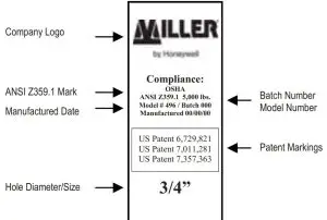
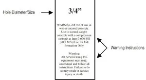
LABELING
The following label must remain affixed to this product.
INSPECTION AND MAINTAINANCE LOG

Honeywell Safety Products — PH: 1-800-873-5242 FX: 1-800-892-4078 — www.millerfallprotection.comP.O. Box 271, 1345 15th Street, Franklin, PA 16323 USA
[xyz-ips snippet=”download-snippet”]