milwaukee 48-35-1211 165′ Laser Line Detector User Manual
WARNING To reduce the risk of injury, user must read and understand operator’s manual.
GENERAL POWER TOOL SAFETY WARNINGS
WARNING Read and understand all instructions. Failure to follow all instructions listed below, may result in electric shock, fire and/or serious personal injury. Save all warnings and instructions for future reference.
- Save these instructions – This operator’s manual contains important safety and operating instructions.
WORK AREA SAFETY
- Ensure adequate safeguards at the work site (e.g., surveying site when measuring on roads, construction sites, etc.).
- Avoid dangerous environments. Avoid extended exposure to rain, snow, damp or wet locations. Do not use in the presence of explosive atmospheres (gaseous fumes, dust or flammable materials).
PERSONAL SAFETY
- Do not allow persons unfamiliar with the tool, these safety instructions, and the tool’s opera- tor’s manual to operate the tool. This tool can be dangerous in the hands of untrained users.
- Do not overreach. Keep proper footing and balance at all times. This enables better control of the tool in unexpected situations.
BATTERY USE AND CARE
- This tool is designed to be powered by 2-AA batteries properly inserted into the tool. Do not attempt to use with any other voltage or power supply.
- Do not leave batteries within the reach of children.
- Do not mix new and used batteries. Do not mix brands (or types within brands) of batteries.
- Do not mix rechargeable and non-rechargeable batteries.
- Install batteries according to polarity (+ / –) diagrams.
- Properly dispose of used batteries immediately.
- Do not incinerate or dismantle batteries.
- Under abusive conditions, liquid may be ejected from the battery, avoid contact. If contact ac- cidentally occurs, flush with water. If liquid contacts eyes, additionally seek medical help.Liquid ejected from the battery may cause irritation or burns.
SPECIFIC SAFETY RULES FOR LASER LINE DETECTOR
- Watch out for erroneous results if the tool is defective or if it has been dropped, misused or modified.
- Do not dispose of tool or batteries together with household waste material! Tool and batteries that have reached the end of their life must be collected separately and returned to an environmentally compatible recycling facility.
- Ensure tool magnets are securely mounted to a metal surface. Magnet strength may not hold on thin metal surfaces, causing the tool to fall.
- Maintain labels and nameplates. These carry important information. If unreadable or missing, contact a MILWAUKEE service facility for a free replacement.
- The device conforms to the most stringent requirements of the relevant Electromagnetic Compatibility (EMC) Standards and Regulations. Yet, the possibility of causing interference in other devices cannot be totally excluded.
- CAUTION Use of controls or adjustments or performance of procedures other than those specified herein may result in hazardous radiation exposure.
- Be sure to power off instrument after use. When instrument will not be used for a long period, place it in storage after removing batteries.
![]() Federal Communications Commission
Federal Communications Commission
WARNING Changes or modifications to this unit not expressly ap- proved by the party responsible for compliance could void the user’s authority to operate the equipment.This equipment has been tested and found to comply with the limits for a Class B digital device, pursuant to Part 15 of the FCC Rules. These limits are designedto provide reasonable protection against harmful interference in a residential installation. This equipment generates, uses and can radiate radio frequencyenergy and, if not installed and used in accordance with the instructions, may cause harmful interference to radio communications.
However, there is no guarantee that interference will not occur in a particular installation. If this equipment does cause harmful interference to radio or televi- sion reception, which can be determined by turning the equipment off and on, the user is encouraged to try to correct the interference by one or more of the following measures:
- Reorient or relocate the receiving antenna.
- Increase the separation between the equipment and receiver.
- Consult the dealer or an experienced radio/TV technician for help.
FUNCTIONAL DESCRIPTION
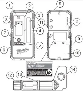
- Speaker
- Laser locator indicator LEDs
- Sensor
- Center line
- Accuracy mode button
- Volume button
- Power button
- Display
- Magnets
- Battery door
- Clamp connection thread
- Clamping knob
- Clamping jaws
- Attachment knob
SYMBOLOGY
- V: Volts
 : Direct Current
- : Magnets
- : Read operator’s manual
SPECIFICATIONS
- Cat. No: 48-35-1211
- Voltage : 3 V (2xAA) LR6
- Reception Angle: ±40°
- Measuring Accuracy Fine: ±0.03″ @ 33′
- Measuring Accuracy Course: ±0.04″ @ 33′
- Wavelength Compatibility: 510-530 nm
- Storage Temp: -4°F to 140°F
- Working Range: 15′ up to 165′ (dependent on laser source)
- Receiving Area: 3″
- Ingress Protection: IP54
- Center Indication (from top): 2-1/2″
- Auto Shut Off: 15 min
- NO button press: 3 hrs
- Operating Temperature: 14°F to 104°F
ASSEMBLY
Changing the Battery
Only use alkaline batteries. Do not use zinc-carbon batteries. If the laser will not be used for a long time, remove the batteries as a protection against corrosion.Change batteries when the battery indication begins flashing. To change the batteries:
- Lift latch to open battery door.
- Insert two AA batteries according to the +/- polarity marked in the compartment.
- Install the battery door securely
Fuel Gauge
To determine the amount of charge left in the battery, turn the tool ON. Charge will show in the display: Full, 3/4, 1/2 and Low Battery warning.

- Battery life may vary by brand/age. Replace the batteries as soon as possible.
OPERATION
WARNING To reduce the risk of injury or temporary effects on vision, do not look directly into the laser when it is on.CAUTION Use of controls or adjustments or performance of procedures other than those specified herein may result in hazardous radiation exposure.NOTICE Perform the Accuracy Field Check procedure immediately upon unboxing of each new Laser Level Detector and before exposure to job site conditions. See “Accuracy Field Check” for information.
Turning On/Off
To turn on the laser detector, press the Power Button ![]() until the units BEEPS and ICONS and LEDs Flash.To turn off the laser detector, press and hold the power button
until the units BEEPS and ICONS and LEDs Flash.To turn off the laser detector, press and hold the power button ![]() for more than 2 seconds. Unit will automatically turn off after 15 minutes with NO but- tons pressed and NO lasers detected, 3 hours with laser detected and NO buttons pressed.
for more than 2 seconds. Unit will automatically turn off after 15 minutes with NO but- tons pressed and NO lasers detected, 3 hours with laser detected and NO buttons pressed.
Using the Laser Detector
- Press the Power Button to toggle between Back Light ON and Back Light OFF.
- Press the Volume Button to toggle between volume options: High Volume (Default) Low Volume Mute/Silent
- Press the Accuracy Mode Bottom to toggle between accuracy options: Fine (Default) Coarse
- Hold the detector so the sensor is facing the laser source. For best results, ensure the detector is level or plumb to the ground and the sensor is perpendicular to the light source.
- Slowly move the detector up/down or left/ right in the general area of the projected laser beam.
- Once the beam is detected, use the Display or LED indication to align the Center Line of the detector with the Laser Beam*.*Use with MILWAUKEE Laser Levels for best results.
Clamp
To use clamp, align locating posts with the back of the Detector.Tighten attachment knob until secure.Use clamping knob to open/close knobs and attach to grade rod, 2×4 or similar.
Laser Locating Display and Audible Indicator
An arrow will be displayed to indicate which direction the user must move the Detector in order to align the Center Line with Laser Beam being detected.Depending which direction, the speaker will beep at either 10 hz (fast) or 4 hz (slow) to indicate which direction to move the detector.
- A solid line will be displayed when the detector center line is aligned with the laser beam being detected. The speaker will play a solid tone and the Green LED will blink.
- When the laser beam being detected is left of the detector center line, an arrow pointing left will be displayed. The speaker will beep quickly at 10 hz and the Red LED will blink.
- When the laser beam being detected is right of the detector center line, an arrow pointing right will be displayed. The speaker will beep slowly at 4 hz and the Blue LED will blink.
- Side LEDs supply the same color and sound indicators.
Troubleshooting
If the tool does not turn on:
- Ensure batteries are inserted correctly according to the +/- polarity marked in the compartment.
- Replace batteries that may be at the end of life.
- Ensure the tool’s internal temperature is within specified operating ranges. If stored in excessive heat or cold, allow at least 2 hours to acclimate to ambient temperature before turning on the tool.If problem persists, please contact a MILWAUKEE service facility for support.
ACCURACY FIELD CHECK
NOTICE Perform the Accuracy Field Check procedure immediately upon unboxing of each new Laser Level Detector and before exposure to job site conditions. See “Accuracy Field Check” for information. Should any deviation from listed product accuracy be found, please con- tact a MILWAUKEE service facility. Failure to do so could result in rejection of warranty claim.
Influences on Accuracy
Sunlight or other extreme lighting conditions can inversely impact accuracy. For best results, use indoors or avoid direct sunlight.Abusive treatment of the Laser Level Detector, such as excessive impacts from drop, can lead to devia- tions in product accuracy.Therefore, it is recommended to conduct the Field Check procedure after any impact or before complet- ing any critical jobs.For best results, use with MILWAUKEE Lasers.
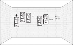
Horizontal Leveling Accuracy
- Set up compatible laser 33′ from flat wall. Turn on lasers horizontal beam.
- Ensure the laser source is self leveled and perpendicular to wall.
- Place detector flat on wall directly in front of the laser source and slightly below the projected laser line.
- Keeping the detector bottom parallel with the ground, raise detector until down arrow appears.
- Lower detector until center line appears.
- Mark a line on the wall – Point I.
- Continue to lower detector until up arrow appears.
- Raise detector until center line appears.
- Mark a line on the wall – Point II.
- Measure the distance between Point I and Point II – divide by 2.
MAINTENANCE
WARNING To reduce the risk of injury, always remove the battery before perform- ing any maintenance. Never disassemble the tool.
Maintain Laser Detector
Maintain tools. If damaged, have the tool repaired before use. Accidents may be caused by poorly maintained tools.
WARNING To reduce the risk of personal in- jury and damage, never immerse your tool in liquid or allow a liquid to flow inside them.
Cleaning
Keep tool housing clean, dry and free of oil or grease.Use only mild soap and a damp cloth to clean the tool since certain cleaning agents and solvents are harmful to plastics and other insulated parts. Some of these include gasoline, turpentine, lacquer thinner, paint thinner, chlorinated cleaning solvents, ammonia and household detergents containing ammonia. Never use flammable or combustible solvents around tools.
Cleaning the Sensor Window
Blow off loose particles with clean compressed air.Carefully wipe the surface with a cotton swab moistened with water.
Repairs
This tool has limited serviceable parts. Do not open housing or disassemble tool. For repairs, return the tool, battery pack and charger to the nearest authorized service center
ACCESSORIES
WARNING Use tools only with specifically designated accessories. Use of any other accessories may create risk of injury.
SERVICE – UNITED STATES
1-800-SAWDUST (1.800.729.3878)Monday-Friday, 7:00 AM – 6:30 PM CSTor visit www.milwaukeetool.com
Contact Corporate After Sales Service Technical Support with technical, service/repair, or warranty questions.Email: [email protected]Become a Heavy Duty Club Member atwww.milwaukeetool.com to receive important notifications regarding your tool purchases.
SERVICE – CANADA
Milwaukee Tool (Canada) Ltd1.800.268.4015Monday-Friday, 7:00 AM – 4:30 PM CSTor visit www.milwaukeetool.ca
LIMITED WARRANTY USA & CANADA
Every MILWAUKEE power tool* (see exceptions below) is warranted to the original purchaser only to be free from defects in material and workmanship. Subject to certain exceptions, MILWAUKEE will repair or replace any part on an electric power tool which, after examination, is determined by MILWAUKEE to be defective in material or workmanship for a period of five (5) years** after the date of purchase unless otherwise noted. Return of the power tool to a MILWAUKEE factory Service Center location or MILWAUKEE Authorized Service Station, freight prepaid and insured, is required. A copy of the proof of purchase should be included with the return product. This warranty does not apply to damage that MILWAUKEE determines to be from repairs made or attempted by anyone other than MILWAUKEE authorized personnel, misuse, altera- tions, abuse, normal wear and tear, lack of maintenance, or accidents. Normal Wear: Many power tools need periodic parts replacement and service to achieve best performance. This warranty does not cover repair when normal use has exhausted the life of a part including, but not limited to, chucks, brushes, cords, saw shoes, blade clamps, o-rings, seals, bum- pers, driver blades, pistons, strikers, lifters, and bumper cover washers.*This warranty does not cover Air Nailers & Staplers; Airless Paint Sprayer; Cordless Battery Packs; Gasoline Driven Portable Power Generators; Hand Tools; Hoist – Electric, Lever & Hand Chain; M12™ Heated Gear; Reconditioned Product; and Test & Measurement Products.There are separate and distinct warranties available for these products.**The warranty period for Job Site Radios, M12™ Power Port, M18™ Power Source, Jobsite Fan and Trade Titan™ Industrial Work Carts is one (1) year from the date of purchase. The warranty period for the M18 FUEL™ 1″ D-Handle High Torque Impact Wrenches, Drain Cleaning Cables, AIRSNAKE™ Drain Cleaning Air Gun Accessories, and REDLITHIUM™ USB Laser Levels is two (2) years from the date of purchase. The warranty period for the M18™ Compact Heat Gun, 8 Gallon Dust Extractor, M18™ Framing Nailers, M18 FUEL™ 1/2″ Ext.Anvil Controlled Torque Impact Wrench w/ ONE-KEY™, M18 FUEL™ 1″ High Torque Impact Wrench w/ ONE-KEY™, M18 FUEL™ 2 Gal. Compact Quiet Compressor, M12™ Laser Levels, 165′ Laser Detector, and M12™ 23GA Pin Nailer is three (3) years from the date of purchase. The warranty period for the LED in the LED Work Light and the LED Upgrade Bulb for the Work Light is the lifetime of the product subject to the limitations above. If during normal use the LED or LED Bulb fails, the part will be replaced free of charge.Warranty Registration is not necessary to obtain the applicable warranty on a MILWAUKEE power tool product. The manufacturing date of the product will be used to determine the warranty period if no proof of pur- chase is provided at the time warranty service is requested.ACCEPTANCE OF THE EXCLUSIVE REPAIR AND REPLACEMENT REMEDIES DESCRIBED HEREIN IS A CONDITION OF THE CON- TRACT FOR THE PURCHASE OF EVERY MILWAUKEE PRODUCT. IF YOU DO NOT AGREE TO THIS CONDITION, YOU SHOULD NOT PURCHASE THE PRODUCT. IN NO EVENT SHALL MILWAUKEE BE LIABLE FOR ANY INCIDENTAL, SPECIAL, CONSEQUENTIAL OR PUNITIVE DAMAGES, OR FOR ANY COSTS, ATTORNEY FEES, EXPENSES, LOSSES OR DELAYS ALLEGED TO BE AS A CONSE QUENCE OF ANY DAMAGE TO, FAILURE OF, OR DEFECT IN ANY PRODUCT INCLUDING, BUT NOT LIMITED TO, ANY CLAIMS FOR LOSS OF PROFITS. SOME STATES DO NOT ALLOW THE EXCLUSION OR LIMITATION OF INCIDENTAL OR CONSEQUENTIAL DAMAGES, SO THE ABOVE LIMITATION OR EXCLUSION MAY NOT APPLY TO YOU. THIS WARRANTY IS EXCLUSIVE AND IN LIEU OF ALL OTHER EXPRESS WARRANTIES, WRITTEN OR ORAL. TO THE EXTENT PERMITTED BY LAW, MILWAUKEE DISCLAIMS ANY IMPLIED WAR- RANTIES, INCLUDING WITHOUT LIMITATION ANY IMPLIED WAR- RANTY OF MERCHANTABILITY OR FITNESS FOR A PARTICULAR USE OR PURPOSE; TO THE EXTENT SUCH DISCLAIMER IS NOT PERMITTED BY LAW, SUCH IMPLIED WARRANTIES ARE LIMITED TO THE DURATION OF THE APPLICABLE EXPRESS WARRANTY AS DESCRIBED ABOVE. SOME STATES DO NOT ALLOW LIMITATIONS ON HOW LONG AN IMPLIED WARRANTY LASTS, SO THE ABOVE LIMITATION MAY NOT APPLY TO YOU, THIS WARRANTY GIVES YOU SPECIFIC LEGAL RIGHTS, AND YOU MAY ALSO HAVE OTHER RIGHTS WHICH VARY FROM STATE TO STATE.This warranty applies to product sold in the U.S.A. and Canada only.Please consult the ‘Service Center Search’ in the Parts & Service sec- tion of MILWAUKEE’s website www.milwaukeetool.com or call 1.800 SAWDUST (1.800.729.3878) to locate your nearest service facility for warranty and non-warranty service on a Milwaukee electric power tool.
References
[xyz-ips snippet=”download-snippet”]