
![]()
OPERATOR’S MANUAL

Cat. No.2606-20, 2607-20
M18™ CORDLESS 1/2″ DRILL/DRIVER AND HAMMER DRILL/DRIVER
![]() WARNING To reduce the risk of injury, user must read and understand operator’s manual.
WARNING To reduce the risk of injury, user must read and understand operator’s manual.
![]()
GENERAL POWER TOOL SAFETY WARNINGS
![]() WARNING Read all safety warnings, instructions, illustrations and specifications provided with this power tool. Failure to follow all instructions listed below may result in electric shock, fire and/or serious injury. Save all warnings and instructions for future reference. The term “power tool” in the warnings refers to your mains-operated (corded) power tool or battery-operated (cordless) power tool.
WARNING Read all safety warnings, instructions, illustrations and specifications provided with this power tool. Failure to follow all instructions listed below may result in electric shock, fire and/or serious injury. Save all warnings and instructions for future reference. The term “power tool” in the warnings refers to your mains-operated (corded) power tool or battery-operated (cordless) power tool.
WORK AREA SAFETY
- Keep work area clean and well lit. Cluttered or dark areas invite accidents.
- Do not operate power tools in explosive atmospheres, such as in the presence of flammable liquids, gases or dust. Power tools create sparks which may ignite the dust or fumes.
- Keep children and bystanders away while operating a power tool. Distractions can cause you to lose control.
ELECTRICAL SAFETY
- Power tool plugs must match the outlet. Never modify the plug in any way. Do not use any adapter plugs with earthed (grounded) power tools. Unmodified plugs and matching outlets will reduce risk of electric shock.
- Avoid body contact with earthed or grounded surfaces, such as pipes, radiators, ranges and refrigerators. There is an increased risk of electric shock if your body is earthed or grounded.
- Do not expose power tools to rain or wet conditions. Water entering a power tool will increase the risk of electric shock.
- Do not abuse the cord. Never use the cord for carrying, pulling or unplugging the power tool. Keep cord away from heat, oil, sharp edges or moving parts. Damaged or entangled cords increase the risk of electric shock.
- When operating a power tool outdoors, use an extension cord suitable for outdoor use. Use of a cord suitable for outdoor use reduces the risk of electric shock.
- If operating a power tool in a damp location is unavoidable, use a ground fault circuit interrupter (GFCI) protected supply. Use of an GFCI reduces the risk of electric shock.
PERSONAL SAFETY
- Stay alert, watch what you are doing and use common sense when operating a power tool. Do not use a power tool while you are tired or under the influence of drugs, alcohol or medication. A moment of inattention while operating power tools may result in serious personal injury.
- Use personal protective equipment. Always wear eye protection. Protective equipment such as a dust mask, non-skid safety shoes, hard hat or hearing protection used for appropriate conditions will reduce personal injuries.
- Prevent unintentional starting. Ensure the switch is in the off-position before connecting to power source and/or battery pack, picking up or carrying the tool. Carrying power tools with your finger on the switch or energizing power tools that have the switch on invites accidents.
- Remove any adjusting key or wrench before turning the power tool on. A wrench or a key left attached to a rotating part of the power tool may result in personal injury.
- Do not overreach. Keep proper footing and balance at all times. This enables better control of the power tool in unexpected situations.
- Dress properly. Do not wear loose clothing or jewelry. Keep your hair and clothing away from moving parts. Loose clothes, jewelry or long hair can be caught in moving parts.
- If devices are provided for the connection of dust extraction and collection facilities, ensure these are connected and properly used. Use of dust collection can reduce dust-related hazards.
- Do not let familiarity gained from frequent use of tools allow you to become complacent and ignore tool safety principles. A careless action can cause severe injury within a fraction of a second.
POWER TOOL USE AND CARE
- Do not force the power tool. Use the correct power tool for your application. The correct power tool will do the job better and safer at the rate for which it was designed.
- Do not use the power tool if the switch does not turn it on and off. Any power tool that cannot be controlled with the switch is dangerous and must be repaired.
- Disconnect the plug from the power source and/or remove the battery pack, if detachable, from the power tool before making any adjustments, changing accessories, or storing power tools. Such preventive safety measures reduce the risk of starting the power tool accidentally.
- Store idle power tools out of the reach of children and do not allow persons unfamiliar with the power tool or these instructions to operate the power tool. Power tools are dangerous in the hands of untrained users.
- Maintain power tools and accessories. Check for misalignment or binding of moving parts, breakage of parts and any other condition that may affect the power tool’s operation. If damaged, have the power tool repaired before use. Many accidents are caused by poorly maintained power tools.
- Keep cutting tools sharp and clean. Properly maintained cutting tools with sharp cutting edges are less likely to bind and are easier to control.
- Use the power tool, accessories and tool bits etc. in accordance with these instructions, taking into account the working conditions and the work to be performed. Use of the power tool for operations different from those intended could result in a hazardous situation.
- Keep handles and grasping surfaces dry, clean and free from oil and grease. Slippery handles and grasping surfaces do not allow for safe handling and control of the tool in unexpected situations.
BATTERY TOOL USE AND CARE
- Recharge only with the charger specified by the manufacturer. A charger that is suitable for one type of battery pack may create a risk of fire when used with another battery pack.
- Use power tools only with specifically designated battery packs. Use of any other battery packs may create a risk of injury and fire.
- When battery pack is not in use, keep it away from other metal objects, like paper clips, coins, keys, nails, screws or other small metal objects, that can make a connection from one terminal to another. Shorting the battery terminals together may cause burns or a fire.
- Under abusive conditions, liquid may be ejected from the battery; avoid contact. If contact accidentally occurs, flush with water. If liquid contacts eyes, additionally seek medical help. Liquid ejected from the battery may cause irritation or burns.
- Do not use a battery pack or tool that is dam- aged or modified. Damaged or modified batteries may exhibit unpredictable behavior resulting in fire, explosion or risk of injury.
- Do not expose a battery pack or tool to fire or excessive temperature. Exposure to fire or temperature above 265°F (130°C) may cause explosion.
- Follow all charging instructions and do not charge the battery pack or tool outside the temperature range specified in the instructions. Charging improperly or at temperatures outside the specified range may damage the battery and increase the risk of fire.
SERVICE
- Have your power tool serviced by a qualified repair person using only identical replacement parts. This will ensure that the safety of the power tool is maintained.
- Never service damaged battery packs. Service of battery packs should only be performed by the manufacturer or authorized service providers.
SPECIFIC SAFETY RULES FOR DRILL/DRIVER
Safety instructions for all operations
- Wear ear protectors when impact drilling. Exposure to noise can cause hearing loss.
- Hold power tool by insulated gripping surfaces, when performing an operation where the cutting accessory may contact hidden wiring. Cutting accessory contacting a “live” wire may make exposed metal parts of the power tool “live” and could give the operator an electric shock.Safety instructions when using long drill bits
- Never operate at higher speed than the maximum speed rating of the drill bit. At higher speeds, the bit is likely to bend if allowed to rotate freely without contacting the workpiece, resulting in personal injury.
- Always start drilling at low speed and with the bit tip in contact with the workpiece. At higher speeds, the bit is likely to bend if allowed to rotate freely without contacting the workpiece, resulting in personal injury.
- Apply pressure only in direct line with the bit and do not apply excessive pressure. Bits can bend causing breakage or loss of control, resulting in personal injury.
- Always use a side handle when using a 8.0 Ah or higher capacity battery pack; the output torque of some tools may increase. If your drill/driver did not come with a side handle, visit www.milwaukeetool.com for the appropriate accessory handle.
 WARNING To reduce the risk of injury, when working in dusty situations, wear appropriate respiratory protection or use an OSHA compliant dust extraction solution.
- Always use common sense and be cautious when using tools. It is not possible to anticipate every situation that could result in a dangerous outcome. Do not use this tool if you do not understand these operating instructions or you feel the work is beyond your capability; contact Milwaukee Tool or a trained professional for additional information or training.
- Maintain labels and nameplates. These carry important information. If unreadable or missing, contact a MILWAUKEE service facility for a free replacement.
- WARNING Some dust created by power sanding, sawing, grinding, drilling, and other construction activities contains chemicals known to cause cancer, birth defects or other reproductive harm. Some examples of these chemicals are:• lead from lead-based paint• crystalline silica from bricks and cement and other masonry products, and• arsenic and chromium from chemically-treated lumber.
Your risk from these exposures varies, depending on how often you do this type of work. To reduce your exposure to these chemicals: work in a well ventilated area, and work with approved safety equipment, such as those dust masks that are specially designed to filter out microscopic particles.
SYMBOLOGY
V Volts
![]() Direct Current
Direct Current
no XXXX MIN-1 No Load Revolutions per Minute (RPM)
n XXXX MIN-1 Blows per Minute Under Load (BPM)
![]() UL Listing for Canada and U.S.
UL Listing for Canada and U.S.
SPECIFICATIONS
Volts ……………………………………………………. 18 DCBattery Type …………………………………………. M18™Charger Type ………………………………………… M18™Recommended Ambient Operating Temperature …………………. 0°F to 125°FCat. No……………………………………………. 2606-20No Load RPM…………………………………Low 0 – 450, High 0 – 1800Steel ……………………………………………………… 1/2″Wood
Flat Bit ……………………………………………….1-1/8″Auger Bit…………………………………………………. 1″Hole Saw ……………………………………………2-1/8″Screws (dia.)…………………………………………. 1/4″
Cat. No ……………………………………………. 2607-20No Load RPM ………………………………… Low 0 – 450, High 0 – 1800BPM ………………………………………….. Low 0 – 7200, High 0 – 28800Steel ……………………………………………………… 1/2″Wood
Flat Bit ……………………………………………….1-1/8″Auger Bit…………………………………………………. 1″Hole Saw ……………………………………………2-1/8″Screws (dia.)…………………………………………. 1/4″
Masonry………………………………………………… 5/8″
FUNCTIONAL DESCRIPTION
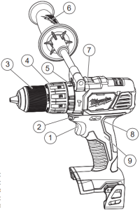
- Trigger
- LED
- Keyless chuck
- Torque selector collar
- Application selector collar (2607-20 only)
- Side handle (not included)
- Speed selector
- Control switch
- Handle
ASSEMBLY
![]() WARNING Recharge only with the charger specified for the battery. For specific charging instructions, read the operator’s manual supplied with your charger and battery.
WARNING Recharge only with the charger specified for the battery. For specific charging instructions, read the operator’s manual supplied with your charger and battery.
Removing/Inserting the BatteryTo remove the battery, push in the release buttons and pull the battery pack away from the tool.
![]() WARNING Always remove battery pack before changing or removing accessories. To insert the battery, slide the pack into the body of the tool. Make sure it latches securely into place.
WARNING Always remove battery pack before changing or removing accessories. To insert the battery, slide the pack into the body of the tool. Make sure it latches securely into place.
![]() WARNING Only use accessories specifically recommended for this tool. Others may be hazardous.To reduce the risk of injury, always use a side handle when using a 9.0 Ah or higher capacity battery pack with this tool. Always brace or hold securely. Ensure side handle is tightened securely before each use.
WARNING Only use accessories specifically recommended for this tool. Others may be hazardous.To reduce the risk of injury, always use a side handle when using a 9.0 Ah or higher capacity battery pack with this tool. Always brace or hold securely. Ensure side handle is tightened securely before each use.
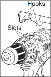
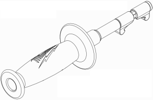
Installing the Side HandleIf your drill/driver did not come with a side handle, visit www.milwaukeetool.com for the appropriate accessory handle.
- To install the side handle, loosen the side handle grip until the hooks are far enough apart to fit into the slots on the gear case ring. Position the side handle on the top, pointing to the left or right. Tighten the side handle grip until it is secure.
- To remove the side handle, loosen the side handle grip until the side handle can be removed. Reposition and tighten securely.
 To install the side handle, loosen the side handle grip until the hooks are far enough apart to fit into the slots on the gear case ring. Position the side handle on the top, pointing to the left or right. Tighten the side handle grip until it is secure.
OPERATION
![]() WARNING To reduce the risk of injury, always wear proper eye protection marked to comply with ANSI Z87.1.When working in dusty situations, wear appropriate respiratory protection or use an OSHA compliant dust extraction solution.Always remove battery pack before changing or removing accessories. Only use accessories specifically recommended for this tool. Others may be hazardous.
WARNING To reduce the risk of injury, always wear proper eye protection marked to comply with ANSI Z87.1.When working in dusty situations, wear appropriate respiratory protection or use an OSHA compliant dust extraction solution.Always remove battery pack before changing or removing accessories. Only use accessories specifically recommended for this tool. Others may be hazardous.
Installing BitsAlways remove the battery before inserting or removing bits. Select the proper style and size bit for the job. This tool is equipped with a spindle lock. The chuck can be tightened with one hand, creating higher grip strengths on the bit.
- To open the chuck jaws, turn the sleeve in the counterclockwise direction. When using drill bits, allow the bit to strike the bottom of the chuck. Center the bit in the chuck jaws and lift it about 1/16″ off of the bottom.When using screwdriver bits, insert the bit far enough for the chuck jaws to grip the hex of the bit.
- To close the chuck jaws, turn the sleeve in the clockwise direction. The bit is secure when the chuck makes a ratcheting sound and the sleeve can not be rotated any further.
- To remove the bit, turn the sleeve in the counter- clockwise direction.
NOTE: A ratcheting sound may be heard when the chuck is opened or closed. This noise is part of the locking feature, and does not indicate a problem with the chuck’s operation.
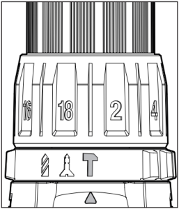
Selecting Drill or Drive Action(Cat. No. 2606-20)
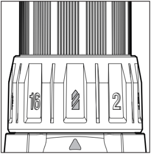
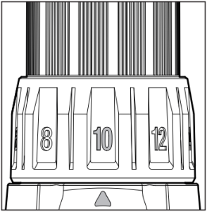
- To use the drilling mode, rotate the torque selector collar until the drill symbol appears in line with the arrow.
- To use the driving mode rotate the torque selector collar until the desired clutch setting appears in line with the arrow.The adjustable clutch, when properly adjusted, will slip at a preset torque to prevent driving the screw too deep into different materials and to prevent damage to the screw or tool.
Selecting Hammer, Drill or Drive Action
 (Cat. No. 2607-20)1. To use the hammer-drilling mode, rotate the application selector collar until the hammer symbol
 ![]() appears in line with the arrow. Apply pressure to the bit to engage the hammering mechanism.NOTE: The number selected on the torque selector collar has no effect on operation of the drill in hammer mode.NOTE: When using carbide bits, do not use water to settle dust. Do not attempt to drill through steel reinforcing rods. This will damage the carbide bits.
appears in line with the arrow. Apply pressure to the bit to engage the hammering mechanism.NOTE: The number selected on the torque selector collar has no effect on operation of the drill in hammer mode.NOTE: When using carbide bits, do not use water to settle dust. Do not attempt to drill through steel reinforcing rods. This will damage the carbide bits.
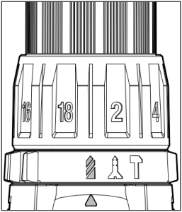 2. To use the drilling only mode, rotate the application selector collar until the drill symbol
 ![]() appears in line with the arrow.NOTE: The number selected on the torque selector collar has no effect on operation of the drill in drilling mode.
appears in line with the arrow.NOTE: The number selected on the torque selector collar has no effect on operation of the drill in drilling mode.
 3. To use the driving screws mode, rotate the application selector collar until the drive symbol
 ![]() appears in line with the arrow. Then rotate the torque selector collar until the desired clutch setting appears in line with the arrow.The adjustable clutch, when properly adjusted, will slip at a preset torque to prevent driving the screw too deep into different materials and to prevent damage to the screw or tool.The torque specifications shown here are approximate values obtained with a fully charged battery pack.
appears in line with the arrow. Then rotate the torque selector collar until the desired clutch setting appears in line with the arrow.The adjustable clutch, when properly adjusted, will slip at a preset torque to prevent driving the screw too deep into different materials and to prevent damage to the screw or tool.The torque specifications shown here are approximate values obtained with a fully charged battery pack.
|
Cat. No. 2606-20 |
||
| Clutch Setting | in. lbs |
Applications |
| 1-56-1011-1516-17 | 15-3032-4043-5055-100 | Small screws in softwood.
Medium screws in softwood or small screws in hardwood. Large screws in softwoods. Medium screws in hardwood or large screws in hardwood with pilot hole. |
|
Cat. No. 2607-20 |
||
| Clutch Setting | in. lbs |
Applications |
| 1-34-67-910-1314-1718 | 28-3031-3334-3941-4749-5557 | Small screws in softwood.
Medium screws in softwood or small screws in hardwood. Large screws in softwoods. Medium screws in hardwood or large screws in hardwood with pilot hole. |
NOTE: Because the settings shown in the table are only a guide, use a piece of scrap material to test the different clutch settings before driving screws into the workpiece.
Selecting Speed
The speed selector is on top of the motor housing. Allow the tool to come to a complete stop before changing speeds. See “Applications” for recommended speeds under various conditions.
- For Low speed, push the speed selector to display “1”.
- For High speed, push the speed selector to display “2”.
Using the Control Switch
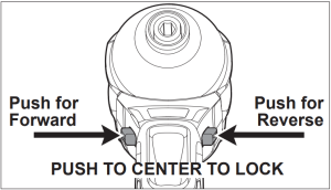
The control switch may be set to three positions:forward, reverse and lock. Due to a lockout mechanism, the control switch can only be adjusted when the ON/OFF switch is not pressed. Always allow the motor to come to a complete stop before using the control switch.
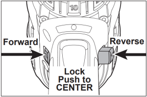 For forward (clockwise) rotation, push in the control switch from the right side of the tool. Check the direction of rotation before use.For reverse (counterclockwise) rotation, push in the control switch from the left side of the tool. Check direction of rotation before use.To lock the trigger, push the control switch to the center position. The trigger will not work while the control switch is in the center locked position. Always lock the trigger or remove the battery pack before performing maintenance, changing accessories, storing the tool and any time the tool is not in use.
![]() WARNING To reduce the risk of injury, always hold or brace securely.
WARNING To reduce the risk of injury, always hold or brace securely.
Starting, Stopping and Controlling Speed
1. To start the tool, grasp the handles firmly and pull the trigger.NOTE: An LED is turned on when the trigger is pulled.2. To vary the speed, increase or decrease the pressure on the trigger. The further the trigger is pulled, the greater the speed.3. To stop the tool, release the trigger. Make sure the bit comes to a complete stop before laying the tool down.
APPLICATIONS
![]() WARNING To reduce the risk of electric shock, check work area for hidden pipes nd wires before drilling or driving screws.
WARNING To reduce the risk of electric shock, check work area for hidden pipes nd wires before drilling or driving screws.
DrillingPlace the bit on the work surface and apply firm pres- sure before starting. Too much pressure will slow the bit and reduce drilling efficiency. Too little pressure will cause the bit to slide over the work area and dull the point of the bit.If the tool begins to stall, reduce pressure slightly to allow the bit to regain speed. If the bit binds, reverse the motor to free the bit from the workpiece.
Drilling in Wood, Composition Materials and PlasticWhen drilling in wood, composition materials and plastic, select the ![]() drill-only operating mode. Start the drill slowly, gradually increasing speed as you drill. When drilling into wood, use wood augers or twist drill bits. Always use sharp bits. When using twist drill bits, pull the bit out of the hole frequently to clear chips from the bit flutes. To reduce the chance of splintering, back work with a piece of scrap wood.Select low speeds for plastics with a low melting point.
drill-only operating mode. Start the drill slowly, gradually increasing speed as you drill. When drilling into wood, use wood augers or twist drill bits. Always use sharp bits. When using twist drill bits, pull the bit out of the hole frequently to clear chips from the bit flutes. To reduce the chance of splintering, back work with a piece of scrap wood.Select low speeds for plastics with a low melting point.
Drilling in MetalWhen drilling in metal, select the ![]() drill-only operating mode. Use high speed steel twist drills or hole saws. Use a center punch to start the hole. Lubricate drill bits with cutting oil when drilling in iron or steel. Use a coolant when drilling in nonferrous metals such as copper, brass or aluminum. Back the material to prevent binding and distortion on breakthrough.
drill-only operating mode. Use high speed steel twist drills or hole saws. Use a center punch to start the hole. Lubricate drill bits with cutting oil when drilling in iron or steel. Use a coolant when drilling in nonferrous metals such as copper, brass or aluminum. Back the material to prevent binding and distortion on breakthrough.
Drilling in MasonryWhen drilling in masonry, select the ![]() hammer drill operating mode. Use high speed carbide-tipped bits. Drilling soft masonry materials such as cinder block requires little pressure. Hard materials like concrete require more pressure. A smooth, even flow of dust indicates the proper drilling rate. Do not let the bit spin in the hole without cutting. Do not use water to settle dust or to cool bit. Both actions will damage the carbide.
hammer drill operating mode. Use high speed carbide-tipped bits. Drilling soft masonry materials such as cinder block requires little pressure. Hard materials like concrete require more pressure. A smooth, even flow of dust indicates the proper drilling rate. Do not let the bit spin in the hole without cutting. Do not use water to settle dust or to cool bit. Both actions will damage the carbide.
Driving Screws and Nut RunningDrill a pilot hole when driving screws into thick or hard materials. Select the ![]() driving screws mode. Set the torque selector collar to the proper position and set the speed to low. Use the proper style and size screwdriver bit for the type of screw you are using. With the screwdriver bit in the screw, place the tip of the screw on the workpiece and apply firm pressure before pulling the trigger. Screws can be removed by reversing the motor.
driving screws mode. Set the torque selector collar to the proper position and set the speed to low. Use the proper style and size screwdriver bit for the type of screw you are using. With the screwdriver bit in the screw, place the tip of the screw on the workpiece and apply firm pressure before pulling the trigger. Screws can be removed by reversing the motor.
OverloadingContinuous overloading may cause permanent dam- age to tool or battery pack.
MAINTENANCE
![]() WARNING To reduce the risk of injury, always unplug the charger and remove the battery pack from the charger or tool before performing any maintenance. Never disassemble the tool, battery pack or charger. Contact a MILWAUKEE service facility for ALL repairs.
WARNING To reduce the risk of injury, always unplug the charger and remove the battery pack from the charger or tool before performing any maintenance. Never disassemble the tool, battery pack or charger. Contact a MILWAUKEE service facility for ALL repairs.
Maintaining Tool
Keep your tool, battery pack and charger in good repair by adopting a regular maintenance program. Inspect your tool for issues such as undue noise, misalignment or binding of moving parts, breakage of parts, or any other condition that may affect the tool operation. Return the tool, battery pack, and charger to a MILWAUKEE service facility for repair. After six months to one year, depending on use, return the tool, battery pack and charger to a MILWAUKEE service facility for inspection.If the tool does not start or operate at full power with a fully charged battery pack, clean the contacts on the battery pack. If the tool still does not work properly, return the tool, charger and battery pack, to a MILWAUKEE service facility for repairs.
![]() WARNING To reduce the risk of personal injury and damage, never immerse your tool, battery pack or charger in liquid or allow a liquid to flow inside them.
WARNING To reduce the risk of personal injury and damage, never immerse your tool, battery pack or charger in liquid or allow a liquid to flow inside them.
Cleaning
Clean dust and debris from vents. Keep handles clean, dry and free of oil or grease. Use only mild soap and a damp cloth to clean, since certain cleaning agents and solvents are harmful to plastics and other insulated parts. Some of these include gasoline, turpentine, lacquer thinner, paint thinner, chlorinated cleaning solvents, ammonia and household deter- gents containing ammonia. Never use flammable or combustible solvents around tools.
Repairs
For repairs, return the tool, battery pack and charger to the nearest authorized service center.
ACCESSORIES
![]() WARNING Use only recommended accessories. Others may be hazardous.For a complete listing of accessories, go online to www.milwaukeetool.com or contact a distributor.
WARNING Use only recommended accessories. Others may be hazardous.For a complete listing of accessories, go online to www.milwaukeetool.com or contact a distributor.
SERVICE – UNITED STATES
1-800-SAWDUST (1.800.729.3878)Monday-Friday, 7:00 AM – 6:30 PM CSTor visit www.milwaukeetool.comContact Corporate After Sales Service Technical Support with technical, service/repair, or warranty questions.
Email: [email protected]
Become a Heavy Duty Club Member at www.milwaukeetool.com to receive important notifications regarding your tool purchases.
SERVICE – CANADA
Milwaukee Tool (Canada) Ltd1.800.268.4015Monday-Friday, 7:00 AM – 4:30 PM CSTor visit www.milwaukeetool.ca
LIMITED WARRANTYUSA & CANADA
Every MILWAUKEE power tool* (see exceptions below) is warranted to the original purchaser only to be free from defects in material and workmanship. Subject to certain exceptions, MILWAUKEE will repair or replace any part on an electric power tool which, after examination, is determined by MILWAUKEE to be defective in material or workmanship for a period of five (5) years** after the date of purchase unless otherwise noted. Return of the power tool to a MILWAUKEE factory Service Center location or MILWAUKEE Authorized Service Station, freight prepaid and insured, is required. A copy of the proof of purchase should be included with the return product. This warranty does not apply to damage that MILWAUKEE determines to be from repairs made or attempted by anyone other than MILWAUKEE authorized personnel, misuse, alterations, abuse, normal wear and tear, lack of maintenance, or accidents.Normal Wear: Many power tools need periodic parts replacement and service to achieve best performance. This warranty does not cover repair when normal use has exhausted the life of a part including, but not limited to, chucks, brushes, cords, saw shoes, blade clamps, o-rings, seals, bumpers, driver blades, pistons, strikers, lifters, and bumper cover washers.*This warranty does not cover Air Nailers & Staplers; Airless Paint Sprayer; Cordless Battery Packs; Gasoline Driven Portable Power Generators; Hand Tools; Hoist – Electric, Lever & Hand Chain; M12™ Heated Gear; Reconditioned Product; and Test & Measurement Products. There are separate and distinct warranties available for these products.**The warranty period for Job Site Radios, M12™ Power Port, M18™ Power Source, Jobsite Fan and Trade Titan™ Industrial Work Carts is one (1) year from the date of purchase. The warranty period for the Drain Cleaning Cables and AIRSNAKE™ Drain Cleaning Air Gun Accessories is two (2) years from the date of purchase. The warranty period for the M18™ Compact Heat Gun, 8 Gallon Dust Extractor, M18™ Framing Nailers, M18 FUEL™ 1/2″ Ext. Anvil Controlled Torque Impact Wrench w/ ONE-KEY™, and the M18 FUEL™ 1″ High Torque Impact Wrench w/ ONE-KEY™ is three (3) years from the date of purchase. The warranty period for the LED in the LED Work Light and the LED Upgrade Bulb for the Work Light is the lifetime of the product subject to the limitations above. If during normal use the LED or LED Bulb fails, the part will be replaced free of charge.Warranty Registration is not necessary to obtain the applicable warranty on a MILWAUKEE power tool product. The manufacturing date of the product will be used to determine the warranty period if no proof of purchase is provided at the time warranty service is requested.ACCEPTANCE OF THE EXCLUSIVE REPAIR AND REPLACEMENT REMEDIES DESCRIBED HEREIN IS A CONDITION OF THE CONTRACT FOR THE PURCHASE OF EVERY MILWAUKEE PRODUCT. IF YOU DO NOT AGREE TO THIS CONDITION, YOU SHOULD NOT PURCHASE THE PRODUCT. IN NO EVENT SHALL MILWAUKEE BE LIABLE FOR ANY INCIDENTAL, SPECIAL, CONSEQUENTIAL OR PUNITIVE DAMAGES, OR FOR ANY COSTS, ATTORNEY FEES, EXPENSES, LOSSES OR DELAYS ALLEGED TO BE AS A CONSEQUENCE OF ANY DAMAGE TO, FAILURE OF, OR DEFECT IN ANY PRODUCT INCLUDING, BUT NOT LIMITED TO, ANY CLAIMS FOR LOSS OF PROFITS. SOME STATES DO NOT ALLOW THE EXCLUSION OR LIMITATION OF INCIDENTAL OR CONSEQUENTIAL DAMAGES, SO THE ABOVE LIMITATION OR EXCLUSION MAY NOT APPLY TO YOU. THIS WARRANTY IS EXCLUSIVE AND IN LIEU OF ALL OTHER EXPRESS WARRANTIES, WRITTEN OR ORAL. TO THE EXTENT PERMITTED BY LAW, MILWAUKEE DISCLAIMS ANY IMPLIED WARRANTIES, INCLUDING WITHOUT LIMITATION ANY IMPLIED WARRANTY OF MERCHANTABILITY OR FITNESS FOR A PARTICULAR USE OR PURPOSE; TO THE EXTENT SUCH DISCLAIMER IS NOT PERMITTED BY LAW, SUCH IMPLIED WARRANTIES ARE LIMITED TO THE DURATION OF THE APPLICABLE EXPRESS WARRANTY AS DESCRIBED ABOVE. SOME STATES DO NOT ALLOW LIMITATIONS ON HOW LONG AN IMPLIED WARRANTY LASTS, SO THE ABOVE LIMITATION MAY NOT APPLY TO YOU, THIS WARRANTY GIVES YOU SPECIFIC LEGAL RIGHTS, AND YOU MAY ALSO HAVE OTHER RIGHTS WHICH VARY FROM STATE TO STATE.This warranty applies to product sold in the U.S.A. and Canada only. Please consult the ‘Service Center Search’ in the Parts & Service section of MILWAUKEE’s website www.milwaukeetool.com or call 1.800. SAWDUST (1.800.729.3878) to locate your nearest service facility for warranty and non-warranty service on a Milwaukee electric power tool.
LIMITED WARRANTY – MEXICO, CENTRAL AMERICA & CARIBBEAN
TECHTRONIC INDUSTRIES’ warranty is for 5 years since the original purchase date.This warranty card covers any defect in material and workmanship on this Product.To make this warranty valid, present this warranty card, sealed/stamped by the distributor or store where you purchased the product, to the Authorized Service Center (ASC). Or, if this card has not been sealed/stamped, present the original proof of purchase to the ASC.Call 55 4160-3547 to find the nearest ASC, for service, parts, accessories or components.Procedure to make this warranty validTake the product to the ASC, along with the warranty card sealed/stamped by the distributor or store where you purchased the product, and any faulty piece or component will be replaced without cost for you. We will cover all freight costs relative with this warranty process.ExceptionsThis warranty is not valid in the following situationsa) When the product is used in a different manner from the end-user guide or instruction manual.b) When the conditions of use are not normal.c) When the product was modified or repaired by people not authorized by TECHTRONIC INDUSTRIES.Note: If cord set is damaged, it should be replaced by an Authorized Service Center to avoid electric risks.
SERVICE AND ATTENTION CENTERCall to 55 4160-3547
IMPORTED AND COMMERCIALIZED BYTECHTRONIC INDUSTRIES MEXICO, S.A. DE C.V.Miguel de Cervantes Saavedra No.301 Piso 5, Torre Norte11520 Colonia Ampliación GranadaMiguel Hidalgo, Ciudad de Mexico, Mexico
Model: ________________________________Date of Purchase: _______________________Distributor or Store Stamp:
MILWAUKEE TOOL13135 West Lisbon RoadBrookfield, WI 53005 USA
58142609d6 961011802-02(A)10/19 Printed in China
![]()
SERVICE PARTS LIST
BULLETIN NO.54-06-2511
| SPECIFY CATALOG NO. AND SERIAL NO. WHEN ORDERING PARTS | REVISED BULLETIN
54-06-2510 |
DATE
Sept. 2017 |
||
|
M18™ 1/2″ DRIVER-DRILL |
||||
| CATALOG NO. | 2606-20 | STARTING SERIAL NO. | F24B or F24C |
WIRING INSTRUCTION SEE PAGE 3 |
![]() EXAMPLE:Component Parts (Small #) Are Included When Ordering The Assembly (Large #).
EXAMPLE:Component Parts (Small #) Are Included When Ordering The Assembly (Large #).
Side Handle Assembly (Optional Equip.)No. 14-34-0035 ♦
To reduce risk of injury, always use a side handle when using a 9.0 Ah or higher battery to operate tool.
♦= Optional, Not Standard Equipment
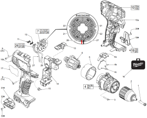
| FIG. | PART NO. | DESCRIPTION OF PART | NO. REQ. |
| 1 | 05-88-1500 | M6 x 27mm LH Chuck Screw |
1 |
| 2 | 42-66-2606 | Keyless 1/2” Chuck |
1 |
| 3 | 06-82-0135 | M3 x 18mm Pan Hd. Plastite T-10 Screw |
4 |
| 4 | 14-29-2606 | Gear Box Assembly |
1 |
| 4a | 45-24-2607 | Speed Selector Slide |
1 |
| 4b | 44-10-2607 | Speed Change Lever |
1 |
| 4c | 40-50-2607 | Torsion Spring |
1 |
| 5 | 18-01-3020 | Service Field |
1 |
| 6 | 16-07-2610 | Service Armature |
1 |
| 7 | 22-22-2607 | Brush Card Assembly |
1 |
| 8 | 06-82-6350 | M3 x 16mm Pan Hd. Plastite T-10 Screw |
7 |
| 9 | 05-88-0675 | M3 x 20mm Pan Hd. Plastite T-10 Screw |
2 |
| 10 | 31-44-2608 | Handle Assembly |
1 |
| 10a | ————— | Left Handle Halve |
1 |
| 10b | ————— | Right Handle Halve |
1 |
| 11 | 05-88-0928 | M3 x 5mm Pan Hd. T-10 Screw |
2 |
| 12 | 45-88-1980 | Spring Washer |
2 |
| 13 | 42-42-2607 | Forward/Reverse Shuttle |
1 |
| 14 | 14-20-2608 | Electronics Assembly (Consists of Switch, PCBA, LED and Battery Terminal Block) |
1 |
| 15 | 40-50-1090 | Terminal Block Spring |
1 |
| 16 | 42-55-2606 | Blow Molded Carrying Case |
1 |
| 17 | 12-20-2607 | Service Nameplate |
1 |
| 18 | 42-70-2653 | Belt Clip Assembly, Optional |
1 |
| 19 | ————— | Belt Clip, Optional |
1 |
| 20 | ————— | Belt Clip Screw, Optional |
1 |
| 21 | ————— | Brush Spring – Right Hand |
2 |
| 22 | ————— | Brush Spring – Left Hand |
2 |
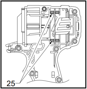
| 24 | 14-46-2394 | Leadwire/Screw/Washer Kit |
1 |
| 27 | ————— | Leadwire Assembly – Black – Right Side |
1 |
| 28 | ————— | Leadwire Assembly – Red – Left Side |
1 |
| 31 | 43-72-0550 | Bit Holder, Optional |
1 |
| 32 | 45-88-1935 | Washer, Optional |
1 |
| 33 | 06-82-5275 | 6-32 x 5/16” Pan Hd. T-15 Screw, Optional |
1 |
MILWAUKEE ELECTRIC TOOL CORPORATION13135 W. Lisbon Road, Brookfield, WI 53005Drwg. 3
INSTALLING BRUSH SPRINGS ON A BRUSH CARD ASSEMBLY WITH FOUR (4) BRUSHES
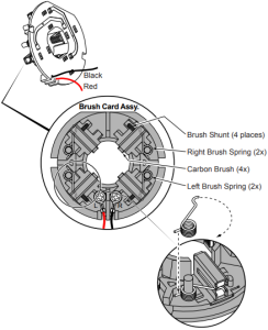
There are two Right Hand Brush Springs and two Left Hand Brush Springs. Follow the instructions below for proper installation.
Be sure carbon brush is in brush tube with brush shunt moving freely in side groove of tube.
Place brush spring over post with short leg positioned downward as shown. Be sure spring is completely down with short leg trapped against ‘Y’ shaped wall on brush card.
While holding spring in place, bring the long leg of spring over the brush tube and through rear opening of tube. Position rounded hook of spring in groove on back of carbon brush. Be sure to check for free movement between carbon brush, brush shunt and brush spring.
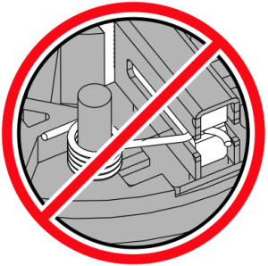

Wrong Correct
![]()
OPERATOR’S MANUAL

Cat. No.2656-20, 2657-20, 2658-20, 2659-20
M18™ 1/4″ HEX IMPACT DRIVER, 1/4″ HEX 2-SPEED IMPACT DRIVER, 3/8″ IMPACT WRENCH & 1/2″ IMPACT WRENCH
![]() WARNING To reduce the risk of injury, user must read and understand operator’s manual.
WARNING To reduce the risk of injury, user must read and understand operator’s manual.
![]()
GENERAL POWER TOOL SAFETY WARNINGS
![]() WARNING Read all safety warnings, instructions, illustrations and specifications provided with this power tool. Failure to follow all instructions listed below may result in electric shock, fire and/or serious injury. Save all warnings and instructions for future reference.The term “power tool” in the warnings refers to your mains-operated (corded) power tool or battery-operated (cordless) power tool.
WARNING Read all safety warnings, instructions, illustrations and specifications provided with this power tool. Failure to follow all instructions listed below may result in electric shock, fire and/or serious injury. Save all warnings and instructions for future reference.The term “power tool” in the warnings refers to your mains-operated (corded) power tool or battery-operated (cordless) power tool.
WORK AREA SAFETY
• Keep work area clean and well lit. Cluttered or dark areas invite accidents.• Do not operate power tools in explosive atmospheres, such as in the presence of flammable liquids, gases or dust. Power tools create sparks which may ignite the dust or fumes.• Keep children and bystanders away while operating a power tool. Distractions can cause you to lose control.
ELECTRICAL SAFETY
• Power tool plugs must match the outlet. Never modify the plug in any way. Do not use any adapter plugs with earthed (grounded) power tools. Unmodified plugs and matching outlets will reduce risk of electric shock.• Avoid body contact with earthed or grounded surfaces, such as pipes, radiators, ranges and refrigerators. There is an increased risk of electric shock if your body is earthed or grounded.• Do not expose power tools to rain or wet conditions. Water entering a power tool will increase the risk of electric shock.• Do not abuse the cord. Never use the cord for carrying, pulling or unplugging the power tool. Keep cord away from heat, oil, sharp edges or moving parts. Damaged or entangled cords increase the risk of electric shock.• When operating a power tool outdoors, use an extension cord suitable for outdoor use. Use of a cord suitable for outdoor use reduces the risk of electric shock.• If operating a power tool in a damp location is unavoidable, use a ground fault circuit interrupter (GFCI) protected supply. Use of an GFCI reduces the risk of electric shock.
PERSONAL SAFETY
• Stay alert, watch what you are doing and use common sense when operating a power tool. Do not use a power tool while you are tired or under the influence of drugs, alcohol or medication. A moment of inattention while operating power tools may result in serious personal injury.• Use personal protective equipment. Always wear eye protection. Protective equipment such as a dust mask, non-skid safety shoes, hard hat or hearing protection used for appropriate conditions will reduce personal injuries.• Prevent unintentional starting. Ensure the switch is in the off-position before connecting to power source and/or battery pack, picking up or carrying the tool. Carrying power tools with your finger on the switch or energizing power tools that have the switch on invites accidents.• Remove any adjusting key or wrench before turning the power tool on. A wrench or a key left attached to a rotating part of the power tool may result in personal injury.• Do not overreach. Keep proper footing and balance at all times. This enables better control of the power tool in unexpected situations.• Dress properly. Do not wear loose clothing or jewelry. Keep your hair and clothing away from moving parts. Loose clothes, jewelry or long hair can be caught in moving parts.• If devices are provided for the connection of dust extraction and collection facilities, ensure these are connected and properly used. Use of dust collection can reduce dust-related hazards.• Do not let familiarity gained from frequent use of tools allow you to become complacent and ignore tool safety principles. A careless action can cause severe injury within a fraction of a second.
POWER TOOL USE AND CARE
• Do not force the power tool. Use the correct power tool for your application. The correct power tool will do the job better and safer at the rate for which it was designed.• Do not use the power tool if the switch does not turn it on and off. Any power tool that cannot be controlled with the switch is dangerous and must be repaired.• Disconnect the plug from the power source and/or remove the battery pack, if detachable, from the power tool before making any adjustments, changing accessories, or storing power tools. Such preventive safety measures reduce the risk of starting the power tool accidentally.• Store idle power tools out of the reach of children and do not allow persons unfamiliar with the power tool or these instructions to operate the power tool. Power tools are dangerous in the hands of untrained users.• Maintain power tools and accessories. Check for misalignment or binding of moving parts, break- age of parts and any other condition that may affect the power tool’s operation. If damaged, have the power tool repaired before use. Many accidents are caused by poorly maintained power tools.• Keep cutting tools sharp and clean. Properly maintained cutting tools with sharp cutting edges are less likely to bind and are easier to control.• Use the power tool, accessories and tool bits etc. in accordance with these instructions, taking into account the working conditions and the work to be performed. Use of the power tool for operations different from those intended could result in a hazardous situation.• Keep handles and grasping surfaces dry, clean and free from oil and grease. Slippery handles and grasping surfaces do not allow for safe handling and control of the tool in unexpected situations.
BATTERY TOOL USE AND CARE
• Recharge only with the charger specified by the manufacturer. A charger that is suitable for one type of battery pack may create a risk of fire when used with another battery pack.• Use power tools only with specifically designated battery packs. Use of any other battery packs may create a risk of injury and fire.• When battery pack is not in use, keep it away from other metal objects, like paper clips, coins, keys, nails, screws or other small metal objects, that can make a connection from one terminal to another. Shorting the battery terminals together may cause burns or a fire.• Under abusive conditions, liquid may be ejected from the battery; avoid contact. If contact accidentally occurs, flush with water. If liquid contacts eyes, additionally seek medical help. Liquid ejected from the battery may cause irritation or burns.• Do not use a battery pack or tool that is damaged or modified. Damaged or modified batteries may exhibit unpredictable behavior resulting in fire, explosion or risk of injury.• Do not expose a battery pack or tool to fire or excessive temperature. Exposure to fire or temperature above 265°F (130°C) may cause explosion.• Follow all charging instructions and do not charge the battery pack or tool outside the temperature range specified in the instructions. Charging improperly or at temperatures outside the specified range may damage the battery and increase the risk of fire.
SERVICE
• Have your power tool serviced by a qualified repair person using only identical replacement parts. This will ensure that the safety of the power tool is maintained.• Never service damaged battery packs. Service of battery packs should only be performed by the manufacturer or authorized service providers.
SPECIFIC SAFETY RULES FOR IMPACT DRIVER/IMPACT WRENCH
• Hold power tool by insulated gripping surfaces, when performing an operation where the fastener may contact hidden wiring. Fasteners contacting a “live” wire may make exposed metal parts of the power tool “live” and could give the operator an electric shock.• Wear ear protectors when impact drilling. Expo- sure to noise can cause hearing loss.• Use only sockets and other accessories specifically designed for use on impact wrenches and drivers. Other sockets and accessories might shatter or break causing injury.
• ![]() WARNING To reduce the risk of injury, when working in dusty situations, wear appropriate respiratory protection or use an OSHA compliant dust extraction solution.• Always use common sense and be cautious when using tools. It is not possible to anticipate every situation that could result in a dangerous outcome. Do not use this tool if you do not understand these operating instructions or you feel the work is beyond your capability; contact Milwaukee Tool or a trained professional for additional information or training.• Maintain labels and nameplates. These carry important information. If unreadable or missing, contact a MILWAUKEE service facility for a free replacement.
WARNING To reduce the risk of injury, when working in dusty situations, wear appropriate respiratory protection or use an OSHA compliant dust extraction solution.• Always use common sense and be cautious when using tools. It is not possible to anticipate every situation that could result in a dangerous outcome. Do not use this tool if you do not understand these operating instructions or you feel the work is beyond your capability; contact Milwaukee Tool or a trained professional for additional information or training.• Maintain labels and nameplates. These carry important information. If unreadable or missing, contact a MILWAUKEE service facility for a free replacement.
• ![]() WARNING Some dust created by power sanding, sawing, grinding, drilling, and other construction activities contains chemicals known to cause cancer, birth defects or other reproductive harm. Some examples of these chemicals are:• lead from lead-based paint• crystalline silica from bricks and cement and other masonry products, and• arsenic and chromium from chemically-treated lumber.Your risk from these exposures varies, depending on how often you do this type of work. To reduce your exposure to these chemicals: work in a well ventilated area, and work with approved safety equipment, such as those dust masks that are specially designed to filter out microscopic particles.
WARNING Some dust created by power sanding, sawing, grinding, drilling, and other construction activities contains chemicals known to cause cancer, birth defects or other reproductive harm. Some examples of these chemicals are:• lead from lead-based paint• crystalline silica from bricks and cement and other masonry products, and• arsenic and chromium from chemically-treated lumber.Your risk from these exposures varies, depending on how often you do this type of work. To reduce your exposure to these chemicals: work in a well ventilated area, and work with approved safety equipment, such as those dust masks that are specially designed to filter out microscopic particles.
SYMBOLOGY
V Volts
![]() Direct Current
Direct Current
no XXXX min-1 No Load Revolutions per Minute (RPM)
n XXXX min-1 Impacts per Minute Under Load (IPM)
![]() UL Listing for Canada and U.S.
UL Listing for Canada and U.S.
SPECIFICATIONS
Volts…………………………………………………….. 18 DCBattery Type ………………………………………….M18™Charger Type…………………………………………M18™Recommended Ambient Operating Temperature………………….0°F to 125°FCat. No……………………………………………… 2656-20RPM……………………………………………………. 0-2750IPM …………………………………………………….. 0-3450Cat. No……………………………………………… 2657-20RPM…………………………. High 0-2750 Low 0-2000IPM ………………………….. High 0-3450 Low 0-2450Cat. No……………………………………………… 2658-20RPM……………………………………………………. 0-2450IPM …………………………………………………….. 0-3350Cat. No……………………………………………… 2659-20RPM……………………………………………………. 0-2450IPM …………………………………………………….. 0-3350
FUNCTIONAL DESCRIPTION
Cat. No. 2657-20
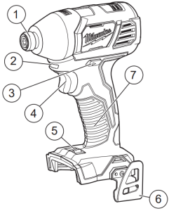
- 1/4″ Hex drive chuck (2656-20, 2657-20)
- LED
- Control switch
- Trigger
- Speed control (2657-20)
- Belt clip
- Handle
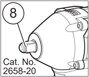
- 3/8″ Square drive anvil (2658-20)
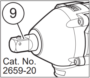
- 1/2″ Square drive anvil with pin detent (2659-20)
ASSEMBLY
![]() WARNING Recharge only with the charger specified for the battery. For specific charging instructions, read the operator’s manual supplied with your charger and battery.
WARNING Recharge only with the charger specified for the battery. For specific charging instructions, read the operator’s manual supplied with your charger and battery.
Removing/Inserting the BatteryTo remove the battery, push in the release buttons and pull the battery pack away from the tool.
![]() WARNING Always remove battery pack before changing or removing accessories.
WARNING Always remove battery pack before changing or removing accessories.
To insert the battery, slide the pack into the body of the tool. Make sure it latches securely into place.
![]() WARNING Only use accessories specifically recommended for this tool. Others may be hazardous. Use only sockets and other accessories specifically designed for use on impact wrenches and drivers. Other sockets and accessories might shatter or break causing injury.
WARNING Only use accessories specifically recommended for this tool. Others may be hazardous. Use only sockets and other accessories specifically designed for use on impact wrenches and drivers. Other sockets and accessories might shatter or break causing injury.
Attaching and Removing Accessories1/2″ Impact Wrench with Pin Detent(Cat. No. 2659-20)
- Use only the appropriate size Square Drive Sockets.
- To attach a socket, align the hole in the accessory with the detent pin on the anvil. Hold the detent pin in while pushing the socket onto the anvil. The detent pin will snap into place in the hole to secure the socket.
- To remove the socket, insert a nail or other thin object into the hole in the accessory and press in the detent pin. Pull the accessory off the anvil.
3/8″ Impact Wrench(Cat. No. 2658-20)
- Use only the appropriate size Square Drive Sockets.
- To attach a socket, align the accessory with the anvil and push it firmly over the retaining ring.
- To remove the accessory, pull the accessory off the anvil.
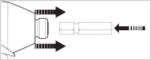
1/4″ Hex Impact Driver(Cat. No. 2656-20, 2657-20)
This impact driver is intended for use with drill and driver bits.
- To attach an accessory, press the shank into the hex drive chuck.
- To remove the accessory, pull out the ring and remove the accessory. Release the ring.
OPERATION
![]() WARNING To reduce the risk of injury, always wear proper eye protection marked to comply with ANSI Z87.1.When working in dusty situations, wear appropriate respiratory protection or use an OSHA compliant dust extraction solution.Always remove battery pack before changing or removing accessories. Only use accessories specifically recommended for this tool. Others may be hazardous.
WARNING To reduce the risk of injury, always wear proper eye protection marked to comply with ANSI Z87.1.When working in dusty situations, wear appropriate respiratory protection or use an OSHA compliant dust extraction solution.Always remove battery pack before changing or removing accessories. Only use accessories specifically recommended for this tool. Others may be hazardous.
Using the Control SwitchThe control switch may be set to three positions: forward, reverse and lock. Due to a lockout mechanism, the control switch can only be adjusted when the ON/OFF switch is not pressed. Always allow the motor to come to a complete stop before using the control switch.
1. For forward (clockwise) rotation, push the control switch in the direction shown. Check the direction of rotation before use.2. For reverse (counterclockwise) rotation, push the control switch in the direction shown. Check the direction of rotation before use.3. To lock the trigger, push the control switch to the center position. The trigger will not work when the control switch is in the locked position.Always remove the battery pack before performing maintenance or changing accessories. Always lock the trigger or remove the battery pack before storing the tool and any time the tool is not in use.
Selecting SpeedAllow the tool to come to a complete stop before changing speeds.
- For Low speed, push the speed selector to display “1”.
- For High speed, push the speed selector to display “2”.
Starting, Stopping and Controlling SpeedThese tools may be operated at any speed from 0 to full speed.
- To start the tool, pull the trigger.NOTE: An LED is turned on when the trigger is pulled.
- To vary the driving speed, simply increase or decrease pressure on the trigger. The further the trigger is pulled, the greater the speed.
- To stop the tool, release the trigger and the electric brake stops the tool instantly.
APPLICATIONS
![]() WARNING To reduce the risk of electric shock, check work area for hidden pipes and wires before drilling or driving screws.
WARNING To reduce the risk of electric shock, check work area for hidden pipes and wires before drilling or driving screws.
Impacting TechniquesThe longer a bolt, screw, or nut is impacted, the tighter it will become. To help prevent damaging the fasteners or workpieces, avoid excessive impacting. Be particularly careful when impacting smaller fasteners because they require less impacting to reach optimum torque.Practice with various fasteners, noting the length of time required to reach the desired torque. Check the tightness with a hand-torque wrench. If the fasteners are too tight, reduce the impacting time. If they are not tight enough, increase the impacting time.Oil, dirt, rust or other matter on the threads or under the head of the fastener affects the degree of tightness.The torque required to loosen a fastener averages 75% to 80% of the tightening torque, depending on the condition of the contacting surfaces.On light gasket jobs, run each fastener down to a relatively light torque and use a hand torque wrench for final tightening.
MAINTENANCE
![]() WARNING To reduce the risk of injury, always unplug the charger and remove thebattery pack from the charger or tool before performing any maintenance. Never disassemble the tool, battery pack or charger. Contact a MILWAUKEE service facility for ALL repairs.
WARNING To reduce the risk of injury, always unplug the charger and remove thebattery pack from the charger or tool before performing any maintenance. Never disassemble the tool, battery pack or charger. Contact a MILWAUKEE service facility for ALL repairs.
Maintaining ToolKeep your tool, battery pack and charger in good repair by adopting a regular maintenance program. Inspect your tool for issues such as undue noise, misalignment or binding of moving parts, breakage of parts, or any other condition that may affect the tool operation. Return the tool, battery pack, and charger to a MILWAUKEE service facility for repair. After six months to one year, depending on use, return the tool, battery pack and charger to a MILWAUKEE service facility for inspection.If the tool does not start or operate at full power with a fully charged battery pack, clean the contacts on the battery pack. If the tool still does not work prop- erly, return the tool, charger and battery pack, to a MILWAUKEE service facility for repairs.
![]() WARNING To reduce the risk of personal injury and damage, never immerse your tool, battery pack or charger in liquid or allow a liquid to flow inside them.
WARNING To reduce the risk of personal injury and damage, never immerse your tool, battery pack or charger in liquid or allow a liquid to flow inside them.
CleaningClean dust and debris from vents. Keep handles clean, dry and free of oil or grease. Use only mild soap and a damp cloth to clean, since certain cleaning agents and solvents are harmful to plastics and other insulated parts. Some of these include gasoline, turpentine, lacquer thinner, paint thinner, chlorinated cleaning solvents, ammonia and household deter- gents containing ammonia. Never use flammable orcombustible solvents around tools.
RepairsFor repairs, return the tool, battery pack and charger to the nearest authorized service center.
ACCESSORIES
![]() WARNING Use only recommended accessories. Others may be hazardous.For a complete listing of accessories, go online to www.milwaukeetool.com or contact a distributor.
WARNING Use only recommended accessories. Others may be hazardous.For a complete listing of accessories, go online to www.milwaukeetool.com or contact a distributor.
SERVICE – UNITED STATES
1-800-SAWDUST (1.800.729.3878)Monday-Friday, 7:00 AM – 6:30 PM CSTor visit www.milwaukeetool.com
Contact Corporate After Sales Service Technical Support with technical, service/repair, or warranty questions.
Email: [email protected]
Become a Heavy Duty Club Member at www.milwaukeetool.com to receive important notifications regarding your tool purchases.
SERVICE – CANADA
Milwaukee Tool (Canada) Ltd1.800.268.4015Monday-Friday, 7:00 AM – 4:30 PM CSTor visit www.milwaukeetool.ca
LIMITED WARRANTYUSA & CANADA
Every MILWAUKEE power tool* (see exceptions below) is warranted to the original purchaser only to be free from defects in material and workmanship. Subject to certain exceptions, MILWAUKEE will repair or replace any part on an electric power tool which, after examination, is determined by MILWAUKEE to be defective in material or workmanship for a period of five (5) years** after the date of purchase unless otherwise noted. Return of the power tool to a MILWAUKEE factory Service Center location or MILWAUKEE Authorized Service Station, freight prepaid and insured, is required. A copy of the proof of purchase should be included with the return product. This warranty does not apply to damage that MILWAUKEE determines to be from repairs made or attempted by anyone other than MILWAUKEE authorized personnel, misuse, alterations, abuse, normal wear and tear, lack of maintenance, or accidents.Normal Wear: Many power tools need periodic parts replacement and service to achieve best performance. This warranty does not cover repair when normal use has exhausted the life of a part including, but not limited to, chucks, brushes, cords, saw shoes, blade clamps, o-rings, seals, bumpers, driver blades, pistons, strikers, lifters, and bumper cover washers.*This warranty does not cover Air Nailers & Staplers; Airless Paint Sprayer; Cordless Battery Packs; Gasoline Driven Portable Power Generators; Hand Tools; Hoist – Electric, Lever & Hand Chain; M12™ Heated Gear; Reconditioned Product; and Test & Measurement Products. There are separate and distinct warranties available for these products.**The warranty period for Job Site Radios, M12™ Power Port, M18™ Power Source, Jobsite Fan and Trade Titan™ Industrial Work Carts is one (1) year from the date of purchase. The warranty period for the Drain Cleaning Cables and AIRSNAKE™ Drain Cleaning Air Gun Accessories is two (2) years from the date of purchase. The warranty period for the M18™ Compact Heat Gun, 8 Gallon Dust Extractor, M18™ Framing Nailers, M18 FUEL™ 1/2″ Ext. Anvil Controlled Torque Impact Wrench w/ ONE-KEY™, and the M18 FUEL™ 1″ High Torque Impact Wrench w/ ONE-KEY™ is three (3) years from the date of purchase. The warranty period for the LED in the LED Work Light and the LED Upgrade Bulb for the Work Light is the lifetime of the product subject to the limitations above. If during normal use the LED or LED Bulb fails, the part will be replaced free of charge.Warranty Registration is not necessary to obtain the applicable warranty on a MILWAUKEE power tool product. The manufacturing date of the product will be used to determine the warranty period if no proof of purchase is provided at the time warranty service is requested.ACCEPTANCE OF THE EXCLUSIVE REPAIR AND REPLACEMENT REMEDIES DESCRIBED HEREIN IS A CONDITION OF THE CONTRACT FOR THE PURCHASE OF EVERY MILWAUKEE PRODUCT. IF YOU DO NOT AGREE TO THIS CONDITION, YOU SHOULD NOT PURCHASE THE PRODUCT. IN NO EVENT SHALL MILWAUKEE BE LIABLE FOR ANY INCIDENTAL, SPECIAL, CONSEQUENTIAL OR PUNITIVE DAMAGES, OR FOR ANY COSTS, ATTORNEY FEES, EXPENSES, LOSSES OR DELAYS ALLEGED TO BE AS A CONSEQUENCE OF ANY DAMAGE TO, FAILURE OF, OR DEFECT IN ANY PRODUCT INCLUDING, BUT NOT LIMITED TO, ANY CLAIMS FOR LOSS OF PROFITS. SOME STATES DO NOT ALLOW THE EXCLUSION OR LIMITATION OF INCIDENTAL OR CONSEQUENTIAL DAMAGES, SO THE ABOVE LIMITATION OR EXCLUSION MAY NOTAPPLY TO YOU. THIS WARRANTY IS EXCLUSIVE AND IN LIEU OF ALL OTHER EXPRESS WARRANTIES, WRITTEN OR ORAL.TO THE EXTENT PERMITTED BY LAW, MILWAUKEE DISCLAIMS ANY IMPLIED WARRANTIES, INCLUDING WITHOUT LIMITATION ANY IMPLIED WARRANTY OF MERCHANTABILITY OR FITNESS FOR A PARTICULAR USE OR PURPOSE; TO THE EXTENT SUCH DISCLAIMER IS NOT PERMITTED BY LAW, SUCH IMPLIED WARRANTIES ARE LIMITED TO THE DURATION OF THE APPLICABLE EXPRESS WARRANTY AS DESCRIBED ABOVE. SOME STATES DO NOT ALLOW LIMITATIONS ON HOW LONG AN IMPLIED WARRANTY LASTS, SO THE ABOVE LIMITATION MAY NOT APPLY TO YOU, THIS WARRANTY GIVES YOU SPECIFIC LEGAL RIGHTS, AND YOU MAY ALSO HAVE OTHER RIGHTS WHICH VARY FROM STATE TO STATE.This warranty applies to product sold in the U.S.A. and Canada only.Please consult the ‘Service Center Search’ in the Parts & Service section of MILWAUKEE’s website www.milwaukeetool.com or call 1.800.SAWDUST (1.800.729.3878) to locate your nearest service facility for warranty and non-warranty service on a Milwaukee electric power tool.
LIMITED WARRANTY – MEXICO,CENTRAL AMERICA & CARIBBEAN
TECHTRONIC INDUSTRIES’ warranty is for 5 years since the original purchase date.This warranty card covers any defect in material and workmanship on this Product.To make this warranty valid, present this warranty card, sealed/stamped by the distributor or store where you purchased the product, to the Authorized Service Center (ASC). Or, if this card has not been sealed/stamped, present the original proof of purchase to the ASC.Call 55 4160-3547 to find the nearest ASC, for service, parts, accessories or components.Procedure to make this warranty validTake the product to the ASC, along with the warranty card sealed/stamped by the distributor or store where you purchased the product, and any faulty piece or component will be replaced without cost for you. We will cover all freight costs relative with this warranty process.ExceptionsThis warranty is not valid in the following situationsa) When the product is used in a different manner from the end-user guide or instruction manual.b) When the conditions of use are not normal.c) When the product was modified or repaired by people not authorized by TECHTRONIC INDUSTRIES. Note: If cord set is damaged, it should be replaced by an Authorized Service Center to avoid electric risks.
SERVICE AND ATTENTION CENTERCall to 55 4160-3547
IMPORTED AND COMMERCIALIZED BYTECHTRONIC INDUSTRIES MEXICO, S.A. DE C.V.Miguel de Cervantes Saavedra No.301 Piso 5, Torre Norte11520 Colonia Ampliación GranadaMiguel Hidalgo, Ciudad de Mexico, Mexico
Model: ______________________________Date of Purchase: _____________________Distributor or Store Stamp:
MILWAUKEE TOOL13135 West Lisbon RoadBrookfield, WI 53005 USA
58142613d5 961012795-02(A)01/20 Printed in Vietnam
SERVICE PARTS LIST
BULLETIN NO.54-26-2503
![]() EXAMPLE:Component Parts (Small #) Are Included When Ordering The Assembly (Large #).
EXAMPLE:Component Parts (Small #) Are Included When Ordering The Assembly (Large #).
*= Part number change from previous service parts list.
| SPECIFY CATALOG NO. AND SERIAL NO. WHEN ORDERING PARTS | REVISED BULLETIN
54-26-2502 |
DATE
July 2019 |
||
| M18™ 1/4″ Hex Impact Driver – Single Speed | ||||
| CATALOG NO. | 2656-20 | STARTING SERIAL NO. | F26D | WIRING INSTRUCTION
SEE PAGE 2 |
As an aid to assembly, carefully lower the complete front end of tool (gearcase / impacting system) onto the gearcase end cap (with o-ring installed). Gently press front end assembly onto gearcase end cap. Be careful to apply pressure evenly and squarely by hand.

NOTE: Components of the impacting assembly (58) can drop out of the gearcase (54). Care must be taken to hold those elements in place when assembling onto the gearcase end cap (24).
Rubber Slugs are (4x) per handle halve (8x total)
| FIG. | PART NO. | DESCRIPTION OF PART | NO. REQ. |
| 1 | 34-60-0725 | Retaining Ring | 1 |
| 2 | 45-88-2026 | Washer | 1 |
| 3 | 40-50-1470 | Spring | 1 |
| 4 | 45-22-2657 | Sleeve | 1 |
| 8 | 45-88-2653 | Nylon Washer | 1 |
| 9 | 02-02-0170 | 4.0mm Steel Ball | 2 |
| 10 | ————— | 1/4″ Hex Anvil | 1 |
| 11 | 02-02-1300 | 5.0mm Steel Ball | 1 |
| 16 | 02-02-0180 | 4.7mm Steel Ball | 2 |
| *22 | 32-65-2656 | Ring Gear | 1 |
| *24 | 44-66-0418 | Gearcase End Cap with Ball Bearing | 1 |
| 25 | 45-30-2653 | Rubber Slug | 8 |
| 26 | 18-01-2657 | Field Assembly | 1 |
| 31 | 22-22-2657 | Brush Card Assembly | 1 |
| 32 | 45-88-1980 | Spring Washer | 2 |
| 33 | 05-88-0926 | M3 x 5mm Pan Hd. T-10 Screw | 2 |
| 34 | 40-50-1090 | Terminal Block Spring | 1 |
| 35 | ————— | Handle Halve – Left | 1 |
| 37 | ————— | Belt Clip | 1 |
| 38 | 06-82-0130 | 6-32 x 5/16″ Pan Hd. T-15 Mach. Screw | 1 |
| 40 | 45-24-2657 | Forward/Reverse Shuttle | 1 |
| 47 | 42-55-2657 | Carrying Case | 1 |
| 48 | 12-20-2618 | Service Nameplate | 1 |
| 49 | ————— | Handle Halve – Right | 1 |
| 50 | 06-82-6350 | M3 X 16mm Pan Hd. ST T-10 Screw | 8 |
| *54 | 28-50-2658 | Gearcase with Bushing | 1 |
| *55 | 14-30-2669 | Gearcase Assembly | 1 |
| 57 | 23-66-2659 | Electronics Assembly – Single Speed Consists of: On-Off Switch, PCBA, LED and Battery Terminal Block | 1 |
| *58 | 14-46-2759 | Impacting Assembly | 1 |
| 59 | 16-07-2657 | Armature Assembly | 1 |
| 60 | 42-70-2653 | Belt Clip Assembly | 1 |
| 62 | 06-82-7336 | 4-20 x 3/4″ Pan Hd. Plastite T-10 Screw | 1 |
| *70 | 31-44-2661 | Handle Assembly – Single Speed | 1 |
| 71 | ————— | Leadwire Assembly – Black – Right Side | 1 |
| 72 | ————— | Leadwire Assembly – Red – Left Side | 1 |
| 73 | ————— | Brush Spring – Right | 2 |
| 74 | ————— | Brush Spring – Left | 2 |
| 75 | 42-06-2659 | 1/4″ Hex Anvil Assembly | 1 |
| 76 | 14-46-2394 | Leadwire/Screw/Washer Kit | 1 |
| 77 | 10-20-1126 | Warning Label (Not Shown) | 1 |
| *80 | 34-40-0246 | O-Ring | 1 |
FIG. LUBRICATION(Type ‘J’ Grease, No. 49-08-4220):
10 Lightly coat front washer surface of anvil (10) with grease, place a dab in the ball holes of anvil.
22,58 Lightly coat the I.D. of the ring gear (22) and the center of the planet gears of impacting assembly with grease.
54 Coat inside of bushing inside front gearcase with grease.
59 Coat pinion of armature assembly (59) with grease.
MILWAUKEE TOOL • www.milwaukeetool.com13135 W. Lisbon Road, Brookfield, WI 53005Drwg. 1

Model 2656-20 Shown
References
[xyz-ips snippet=”download-snippet”]