
![]()
OPERATOR’S MANUALMANUEL de L’UTILISATEURMANUAL del OPERADOR

Cat. No. / No de cat.2825-20M18 FUEL™ ATTACHMENT SYSTEM W/ QUIK-LOK™POWER HEAD
![]() WARNING To reduce the risk of injury, user must read and understand operator’s manual.AVERTISSEMENT Afin de réduire le risque de blessures, l’utilisateur doit lire et bien comprendre le manuel.ADVERTENCIA Para reducir el riesgo de lesiones, el usuario debe leer y entender el manual.
WARNING To reduce the risk of injury, user must read and understand operator’s manual.AVERTISSEMENT Afin de réduire le risque de blessures, l’utilisateur doit lire et bien comprendre le manuel.ADVERTENCIA Para reducir el riesgo de lesiones, el usuario debe leer y entender el manual.
GENERAL POWER TOOL SAFETY WARNINGS
 WARNINGRead all safety warnings, instructions, illustrations, and specifications provided with this power tool. Failure to follow all instructions listed below may result in electric shock, fire, and/or serious injury. Save all warnings and instructions for future reference. The term “power tool” in the warnings refers to your mains-operated (corded) power tool or battery-operated (cordless) power tool.
WORK AREA SAFETY
- Keep work area clean and well lit. Cluttered or dark areas invite accidents.
- Do not operate power tools in explosive atmospheres, such as in the presence of flammable liquids, gases or dust. Power tools create sparks that may ignite dust or fumes.
- Keep children and bystanders away while operating a power tool. Distractions can cause you to lose control.
ELECTRICAL SAFETY
- Power tool plugs must match the outlet. Never modify the plug in any way. Do not use any adapter plugs with earthed (grounded) power tools. Unmodified plugs and matching outlets will reduce the risk of electric shock.
- Avoid body contact with earthed or grounded surfaces, such as pipes, radiators, ranges, and refrigerators. There is an increased risk of electric shock if your body is earthed or grounded.
- Do not expose power tools to rain or wet conditions. Water entering a power tool will increase the risk of electric shock.
- Do not abuse the cord. Never use the cord for carrying, pulling, or unplugging the power tool. Keep cord away from heat, oil, sharp edges or moving parts. Damaged or entangled cords increase the risk of electric shock.
- When operating a power tool outdoors, use an extension cord suitable for outdoor use. The use of a cord suitable for outdoor use reduces the risk of electric shock.
- If operating a power tool in a damp location is unavoidable, use a ground fault circuit interrupter(GFCI) protected supply. The use of a GFCI reduces the risk of electric shock.
PERSONAL SAFETY
- Stay alert, watch what you are doing, and use common sense when operating a power tool. Do not use a power tool while you are tired or under the influence of drugs, alcohol, or medication. A moment of inattention while operating power tools may result in serious personal injury.
- Use personal protective equipment. Always wear eye protection. Protective equipment such as a dust mask, non-skid safety shoes, hard hat, or hearing protection used for appropriate conditions will reduce personal injuries.
- Prevent unintentional starting. Ensure the switch is in the off-position before connecting to a power source and/or battery pack, picking up or carrying the tool. Carrying power tools with your finger on the switch or energizing power tools that have the switch on invites accidents.
- Remove any adjusting key or wrench before turning the power tool on. A wrench or a key left attached to a rotating part of the power tool may result in personal injury.
- Do not overreach. Keep proper footing and balance at all times. This enables better control of the power tool in unexpected situations.
- Dress properly. Do not wear loose clothing or jewelry. Keep your hair and clothing away from moving parts. Loose clothes, jewelry or long hair can be caught in moving parts.
- If devices are provided for the connection of dust extraction and collection facilities, ensure these are connected and properly used. Use of dust collection can reduce dust-related hazards.
- Do not let familiarity gained from frequent use of tools allow you to become complacent and ignore tool safety principles. A careless action can cause severe injury within a fraction of a second.
POWER TOOL USE AND CARE
- Do not force the power tool. Use the correct power tool for your application. The correct power tool will do the job better and safer at the rate at which it was designed.
- Do not use the power tool if the switch does not turn it on and off. Any power tool that cannot be controlled with the switch is dangerous and must be repaired.
- Disconnect the plug from the power source and/ or remove the battery pack, if detachable, from the power tool before making any adjustments, changing accessories, or storing power tools. Such preventive safety measures reduce the risk of starting the power tool accidentally.
- Store idle power tools out of the reach of children and do not allow persons unfamiliar with the power tool or these instructions to operate the power tool. Power tools are dangerous in the hands of untrained users.
- Maintain power tools and accessories. Check for misalignment or binding of moving parts, breakage of parts, and any other condition that may affect the power tool’s operation. If damaged, have the power tool repaired before use. Many accidents are caused by poorly maintained powertools.
- Keep cutting tools sharp and clean. Properly maintained cutting tools with sharp cutting edges are less likely to bind and are easier to control.
- Use the power tool, accessories and tool bits, etc. in accordance with these instructions, taking into account the working conditions and the work to be performed. Use of the power tool for operations different from those intended could result in a hazardous situation.
- Keep handles and grasping surfaces dry, clean, and free from oil and grease. Slippery handles and grasping surfaces do not allow for safe handling and control of the tool in unexpected situations.
BATTERY TOOL USE AND CARE
- Recharge only with the charger specified by the manufacturer. A charger that is suitable for one type of battery pack may create a risk of fire when used with another battery pack.
- Use power tools only with specifically designated battery packs. Use of any other battery packs may create a risk of injury and fire.
- When the battery pack is not in use, keep it away from other metal objects, like paper clips, coins, keys, nails, screws, or other small metal objects, that can make a connection from one terminal to another. Shorting the battery terminals together may cause burns or a fire.
- Under abusive conditions, liquid may be ejected from the battery; avoid contact. If contact accidentally occurs, flush with water. If liquid contacts eyes, additionally seek medical help. Liquid ejected from the battery may cause irritation or burns.
- Do not use a battery pack or tool that is damaged or modified. Damaged or modified batteries may exhibit unpredictable behavior resulting in fire, explosion, or risk of injury.
- Do not expose a battery pack or tool to fire or excessive temperature. Exposure to fire or temperature above 265°F (130°C) may cause an explosion.
- Follow all charging instructions and do not charge the battery pack or tool outside the temperature range specified in the instructions. Chargingimproperly or at temperatures outside the specified range may damage the battery and increase the risk of fire.
SERVICE
- Have your power tool serviced by a qualified repair person using only identical replacement parts. This will ensure that the safety of the power tool is maintained.
- Never service damaged battery packs. Service of battery packs should only be performed by the manufacturer or authorized service providers.
SPECIFIC SAFETY RULES FOR POWERHEAD
- Before use, read this manual, and all manuals and labels of this tool and its attachments. Failure to follow the warnings and instructions may resultin serious injury.
- Before using the battery pack or charger read the operator’s manuals, and any labels on the battery pack, charger, and tool.
- Do not handle battery pack, tool, or charger (including charger plug and terminals) with wet hands.
- Always wear eye, hearing, and head protection, and protective clothing and footwear, according to the operation being performed. Wear heavy, long pants, long sleeves, boots, and gloves. Contain long hair. Do not wear loose clothing or jewelry. Do not wear short pants, sandals, or go barefoot.
- Keep bystanders at least 50′ away during use. Objects may be thrown or ricochet in all directions.
- Do not use blades, brush-cutting wheels, accessories, or attachments other than those recommended by MILWAUKEE. Serious injury or product damage may occur.
- Only use an attachment extension when recommended in the tool attachment operator’s manual.
 WARNINGDo not operate near electric power lines. The unit has not been designed to provide protection from electric shock in the event of contact with electric power lines. Consult local regulations for safe distances from electric power lines and ensure that the operating position is safe and secure before use.
- Inspect the area before using the tool. Remove all debris and hard objects such as rocks, glass, wire, etc. that can ricochet, be thrown, or otherwise cause injury or damage during operation.
- Do not operate the tool without the front handle in place. The front handle must be attached properly during use. Use both hands when operating the tool, according to the attached instructions. Maintain a firm grip. Using one hand could causeloss of control and result in serious injury.
- Brace for unexpected movement when contact is made with a hard object. Loss of control could result in serious injury.
- Keep face, hands, and feet clear of moving parts at all times. Moving parts can cause severe lacerations.
- Thrown objects may ricochet off of hard surfaces, such as walls, trees, and rocks, and cause injury. When possible, do trimming by hand in closed-in areas.
- Use care when using around decorative plants and other obstacles. Accessories will cut/damage many materials.
- Always turn off the tool when transporting from one location to another. Do not carry a tool with a finger on the trigger. Accidental starting can cause serious personal injury.
- Carry the tool by the front handle to avoid accidental starting. Proper handling of the tool will prevent injury.
- Always use common sense and be cautious when using tools. It is not possible to anticipate every situation that could result in a dangerous outcome.Do not use this tool if you do not understand these operating instructions or you feel the work is beyond your capability; contact Milwaukee Tool or a trained professional for additional information or training.
- Maintain labels and nameplates. These carry important information. If unreadable or missing, contact a MILWAUKEE service facility for a freereplacement.
- WARNING Some dust created by power sanding, sawing, grinding, drilling, and other construction activities contains chemicals known to cause cancer, birth defects, or other reproductive harm. Some examples of these chemicals are:
- lead from lead-based paint
- crystalline silica from bricks and cement and other masonry products, and
- arsenic and chromium from chemically treated lumber.Your risk from these exposures varies, depending on how often you do this type of work. To reduce your exposure to these chemicals: work in a well-ventilated area, and work with approved safety equipment, such as those dust masks that are specially designed to filter out microscopic particles
READ AND SAVE ALL INSTRUCTIONS FOR FUTURE USE
SPECIFICATIONS
Cat. No. …………………………………………….2825-20*Volts…………………………………………………….. 18 DCBattery Type ………………………………………….M18™Charger Type…………………………………………M18™RPM ……………………… High 0 – 8680 Low 0 – 6860Recommended AmbientOperating Temperature ………………….0°F to 125°F*Use only with compatible Milwaukee M18 FUEL™ Attachment System w/ Quik-Lok™ components.
SYMBOLOGY

FUNCTIONAL DESCRIPTION
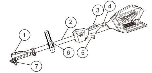
| 1. Quik-Lok ™ release button | 5. Trigger switch |
| 2. Pole | 6. Front handle |
| 3. Trigger lock-out | 7. Lock knob |
| 4. Rear handle |
ASSEMBLY
WARNING Recharge only with the charger specified for the battery. For specific charging instructions, read the operator’s manual supplied with your charger and battery.Removing/Inserting the BatteryTo remove the battery, push the release buttons and pull the battery pack away from the tool.WARNING Always remove the battery pack before changing or removing accessories. To insert the battery, slide the pack into the body of the tool. Make sure it latches securely into place.
WARNING Do not use blades, brush cutting wheels, accessories, or attachments other than those recommended by MILWAUKEE. Serious injury or product damage may occur.Do not operate the tool without the front handle in place. The front handle must be attached properly during use. Use both hands when operating thetool, according to the attached instructions. Maintain a firm grip. Using one hand could cause loss of control and result in serious injury.
Installing the Front Handle

The front handle is shipped uninstalled and must be installed before use.
- Place the two nuts into the front handle detents.
- Insert one bracket into the handle.
- Install the side handle on the powerhead pole, below the “Place Handle Here” sticker, at a distance that is comfortable and provides the best control.
- Wrap the other bracket around the back of the shaft.
- Insert the two screws through the lower bracket and into the side handle.
- Tighten the screws securely using the included key.
WARNINGBefore use, read the manual and labels of the attachment tool. Important assembly and use instructions are provided in the attachment manual. Only use an attachment extension when recommended in the tool attachment manual.
Quik-Lok TM SystemTo install an attachment or extension:
- Remove the battery pack.
- Loosen the lock knob.
- Slide the attachment pole into the Quik-Lok™ latch. The detent on the pole should line up with the slot in the Quik-Lok™ latch.
- Push the sections together securely. Tug on the poles to ensure they are secure.
- Tighten the lock knob.
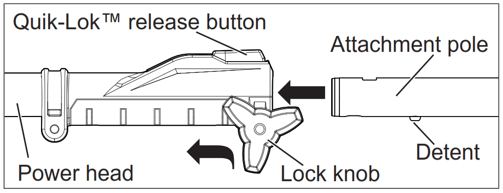
To remove an attachment or extension:
- Remove the battery pack.
- Loosen the lock knob.
- Push in the Quik-Lok™ release button and pull the poles apart.
Attaching the Shoulder Strap (Available as an accessory)
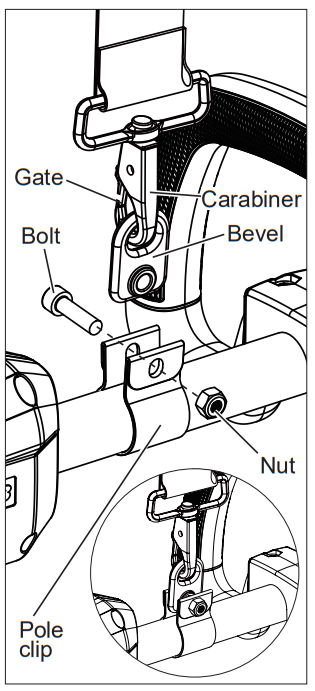
When operating this tool, use the shoulder strap to reduce user fatigue and help in maintaining control during use.
To install the strap:
- Remove the battery pack.
- Fit the pole clip around the powerhead pole between the front handle and rear handle in a location comfortable during use.
- Insert the bolt through the pole clip and strap bevel. Thread the nut onto the bolt and tighten securely.
- Clip the strap carabiner to the bevel.
To wear the strap:
- Put your right arm and head through the strap.
- Adjust the strap clips to change the strap length to fit comfortably.
- Slide the neck pad to the appropriate position.
To unclip the strap:
- Hold the tool by the front handle with your left hand.
- Grip the carabiner with your right hand and unclip by pushing in the gate and it sliding off the bevel.
OPERATION
WARNING To reduce the risk of injury, always wear proper eye protection marked to comply with ANSI Z87.1.Always remove the battery pack before changing or removing accessories or attachments. Use both hands when operating the tool, according to the attached instructions. Maintain a firm grip. Using one hand could cause loss of control and result in serious injury.Inspect the area before using the tool. Remove all debris and hard objects such as rocks, glass, wire, etc. that can ricochet, be thrown, or otherwise cause injury or damage during operation.
Quik-Lok TM Attachments
 This tool can be connected to a number of MILWAUKEE Quik-Lok attachments. Use only in accordance with the attachment’s operator’s manual. specifications and operation instructions are provided in the attachment manual. Use only attachments recommended by MILWAUKEE.TM
Starting/Stopping the Power Head WARNINGTo reduce the risk of injury, always hold the powerhead away from the body keeping clearance between the body and the tool/attachment. Any contact with an attachment or cutting head can result in cuts, burns, and another serious personal injury.Always remove the battery pack and keep hands clear of the trigger and lock-out when carrying or transporting the tool.
- Grasp the tool firmly with both handles.
- To start the tool, squeeze the trigger lock-out and pull the trigger.
- To vary the speed, increase or decrease the pressure on the trigger. The further the trigger is pulled, the greater the speed up to the maximum set by the speed control button.
- To stop the tool release the trigger. Make sure the tool comes to a complete stop before laying the tool down.
MAINTENANCE
WARNINGTo reduce the risk of injury, always unplug the charger and remove the battery pack from the charger or tool before performing any maintenance. Never disassemble the tool, battery pack, or charger. Contact a MILWAUKEE service facility for ALL repairs.
Maintaining Tool
Keep your tool, battery pack, and charger in good repair by adopting a regular maintenance program. Inspect your tool for issues such as undue noise,misalignment or binding of moving parts, breakage of parts, or any other condition that may affect the tool operation. Return the tool, battery pack, and charger to a MILWAUKEE service facility for repair. After six months to one year, depending on use, return the tool, battery pack, and charger to a MILWAUKEE service facility for inspection.If the tool does not start or operate at full power with a fully charged battery pack, clean the contacts on the battery pack. If the tool still does not work properly, return the tool, charger, and battery pack, to a MILWAUKEE service facility for repairs.
WARNINGTo reduce the risk of personal injury and damage, never immerse your tool, battery pack, or charger in liquid or allow a liquid to flow inside them.CleaningClean dust and debris from vents. Keep handles clean, dry, and free of oil or grease. Use only mild soap and a damp cloth to clean, since certain cleaning agents and solvents are harmful to plastics and other insulated parts. Some of these include gasoline, turpentine, lacquer thinner, paint thinner, chlorinated cleaning solvents, ammonia, and household detergents containing ammonia. Never use flammable or combustible solvents around tools.
RepairsFor repairs, return the tool, battery pack, and charger to the nearest authorized service center.
ACCESSORIES
WARNINGUse only recommended accessories. Others may be hazardous. For a complete listing of accessories, go online to www.milwaukeetool.com or contact a distributor.
SERVICE – UNITED STATES1-800-SAWDUST (1.800.729.3878)Monday-Friday, 7:00 AM – 6:30 PM CST or visit www.milwaukeetool.comContact Corporate After Sales Service TechnicalSupport with technical, service/repair, or warranty questions.Email: [email protected]Become a Heavy Duty Club Member atwww.milwaukeetool.com to receive important notifications regarding your tool purchases.
SERVICE – CANADA
Milwaukee Tool (Canada) Ltd1.800.268.4015Monday-Friday, 7:00 AM – 4:30 PM CSTor visit www.milwaukeetool.ca
LIMITED WARRANTY USA & CANADA
Every MILWAUKEE Outdoor Power Equipment Product* (see exceptions below) is warranted to the original purchaser only to be free from defects in material and workmanship. Subject to certain exceptions, MILWAUKEEwill repair or replace any part on outdoor power equipment product which, after examination, is determined by MILWAUKEE to be defective in material or workmanship for a period of three (3) years** after the date of purchase unless otherwise noted. Return of the outdoor power equipment to a MILWAUKEE factory Service Center location or participating MILWAUKEE Authorized Service Station, freight prepaid and insured, is required. A copy of the proof of purchase should be included with the returned product. This warranty does not apply to damage that MILWAUKEE determines to be from repairs made or attempted by anyone other than MILWAUKEE authorized personnel, misuse, alterations, abuse, normal wear and tear, lack of maintenance, or accidents.Normal Wear: Many outdoor power equipment products need periodic parts replacement and service to achieve the best performance. This warranty does not cover repair when normal se has exhausted the life of a part including, but not limited to trimmer head, trimmer head spool, cutting lines, blades, chains, blower tubes, brushes, o-rings, and seals. *This warranty does not cover Cordless Battery Packs or Reconditioned products. There are separate and distinct warranties available for these products.**The warranty period for SWITCH TANK™ tank assemblies, hoses, handles, and wands are one (1) year from the date f purchase. MILWAUKEE does not cover freight or labor charges associated with the inspection and testing of outdoor power equipment products which are found by MILWAUKEE not to be a valid warranty claim. A valid warranty claim must be substantiated by the discovery of defective material r workmanship by MILWAUKEE. ACCEPTANCE OF THE EXCLUSIVE REPAIR AND REPLACEMENT REMEDIES DESCRIBED BY ERIN IS A CONDITION OF THE CONTRACT FOR THE PURCHASE OF EVERY MILWAUKEE PRODUCT. IF YOU DO NOT AGREE TO THIS CONDITION, YOU SHOULD NOT PURCHASE THE PRODUCT. IN NO EVENT SHALL MILWAUKEE BE LIABLE FOR ANY INCIDENTAL, SPECIAL, CONSEQUENTIAL OR PUNITIVE DAMAGES, OR FOR ANY COSTS, ATTORNEY FEES, EXPENSES, LOSSES, OR DELAYS ALLEGED TO BE AS A CONSEQUENCE OF ANY DAMAGE TO, FAILURE OF, OR DEFECT IN ANY PRODUCT INCLUDING, BUT NOT LIMITED TO, ANY CLAIMS FOR LOSS OF PROFITS. SOME STATES DO NOT ALLOW THE EXCLUSION OR LIMITATION OF INCIDENTAL OR CONSEQUENTIAL DAMAGES, SO THE ABOVE LIMITATION OR EXCLUSION MAY NOT APPLY TO YOU. THIS WARRANTY IS EXCLUSIVE AND IN LIEU OF ALL OTHER EXPRESS WARRANTIES, WRITTEN OR ORAL. TO THE EXTENT PERMITTED BY LAW, MILWAUKEE DISCLAIMS ANY IMPLIED WARRANTIES, INCLUDING WITHOUT LIMITATION ANY IMPLIED WARRANTY OF MERCHANTABILITY OR FITNESS FOR A PARTICULAR USE OR PURPOSE; TO THE EXTENT SUCH DISCLAIMER IS NOT PERMITTED BY LAW, SUCH IMPLIED WARRANTIES ARE LIMITED TO THE DURATION OF THE APPLICABLE EXPRESS WARRANTY AS DESCRIBED ABOVE. SOME STATES DO NOT ALLOW LIMITATIONS ON HOW LONG AN IMPLIED WARRANTY LASTS, SO THE ABOVE LIMITATION MAY NOT APPLY TO YOU, THIS WARRANTY GIVES YOU SPECIFIC LEGAL RIGHTS, AND YOU MAY ALSO HAVE OTHER RIGHTS WHICH VARY FROM STATE TO STATE.This warranty applies to products sold in the U.S.A. and Canada only. Please consult the ‘Service Center Search’ in the Parts & Service section of MILWAUKEE’s website www.milwaukeetool.com or call 1.800. SAWDUST (1.800.729.3878) to locate your nearest service facility for warranty and non-warranty service on a Milwaukee electric power tool.
LIMITED WARRANTY – MEXICO, CENTRAL AMERICA & CARIBBEAN
TECHTRONIC INDUSTRIES’ warranty is for 3 years since the original purchase date.This warranty card covers any defect in material and workmanship on this Product.To make this warranty valid, present this warranty card, sealed/stamped by the distributor or store where you purchased the product, to the Authorized Service Center (ASC). Or, if this card has not been sealed/stamped, present the original proof of purchase to the ASC. Call 55 4160-3547 to find the nearest ASC, for service, parts, accessories or components.Procedure to make this warranty valid Take the product to the ASC, along with the warranty card sealed/ stamped by the distributor or store where you purchased the product, and any faulty piece or component will be replaced without cost for you. We will cover all freight costs relative with this warranty process.ExceptionsThis warranty is not valid in the following situationsa) When the product is used in a different manner from the end-user guide or instruction manual.b) When the conditions of use are not normal.c) When the product was modified or repaired by people not authorized by TECHTRONIC INDUSTRIES.Note:If the cord set is damaged, it should be replaced by an Authorized Service Center to avoid electric risks.SERVICE AND ATTENTION CENTERCall 55 4160-3547IMPORTED AND COMMERCIALIZED BYTECHTRONIC INDUSTRIES MEXICO, S.A. DE C.V.Miguel de Cervantes Saavedra No.301 Piso 5, Torre Norte 11520 Colonia Ampliación GranadaMiguel Hidalgo, Ciudad de Mexico, MexicoModel:Date of Purchase:Distributor or Store Stamp:
![]()
SERVICE PARTS LIST
| SPECIFY CATALOG NO. AND SERIAL NO. WHEN ORDERING PARTS | |
| M18™ FUEL™ POWER UNIT | |
| CATALOG NO. 2825-21 | STARTINGK49ASERIAL NO. |
BULLETIN NO. 54-49-2810
| REVISED BULLETIN | DATEAug. 2019 |
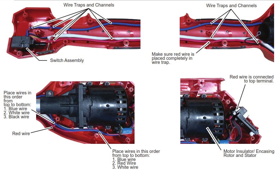
| WIRING INSTRUCTIONSee Page 7 |
| Page 1 Power Unit Exploded View | Page 5 Pole Saw Exploded View |
| Page 2 Edge Trimmer Exploded View | Page 6 Extension Tube Assembly |
| Page 3 String Trimmer Exploded View | Page 7 Wiring Diagram |
| Page 4 Hedge Trimmer Exploded View |
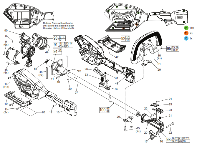
| FIG. | PART NO. | DESCRIPTION OF PART NO. REQ. | |
| 8 | ——— | Motor Insulator – Right | (1) |
| 9 | 06-82-0180 | M3 x 14mm Pan Hd. ST T-10 Screw | (6) |
| 10 | ——- | Lower Cover Halve – Right | (1) |
| 11 | 05-88-1300 | M4 x 28mm Pan Hd. ST T-20 Screw | (2) |
| 12 | 05-88-5375 | , x 13.5 Pan Hd. ST T-20 Screw | (1) |
| 13 | —— | Housing Cover – Right Housing Halve | (1) |
| 14 | 05-88-1200 | M4 x 16mm Pan Hd. ST T-20 Screw | (11) |
| 15 | 05-74-0015 | M6 x 21.5mm, 5mm Hex socket Cap Screw | (4) |
| 19 | 44-60-0068 | Clamping Knob | (1) |
| 20 | —– | Quick Release Casting | (1) |
| 21 | 40-50-1090 | Spring | (1) |
| 22 | 05-78-0027 | M6 x 50mm Hex Hd. Machine Screw | (1) |
| 23 | 45-72-0013 | Quick Change Trigger | (1) |
| 24 | 05-81-0592 | M4 x 6.5mm Flat Head T-15 Screw | (1) |
| 25 | 42-92-0047 | Trigger Cover | (1) |
| 26 | 05-74-0026 | M6 x 30mm Cap Hd. Hex Socket Screw | (1) |
| 29 | 42-68-0292 | Carrier Handle Clip | (2) |
| 30 | 05-55-0006 | M6 Hex Nut | (2) |
| 31 | —— | Carrier Handle | (1) |
| 32 | 45-72-0083 | On-Off Trigger | (1) |
| 33 | 40-50-0374 | Bias Spring | (1) |
| 34 | 40-50-0373 | Spring | (1) |
| 39 | 06-82-5270 | 6-32 x 1/4″ Pan Hd. Tapt. T-15 Screw | (1) |
| 40 | 05-74-0012 | M4 x 20mm Pan Hd. T-20 Machine Screw | (1) |
| 41 | 45-88-0825 | Flat Washer | (1) |
| 42 | 05-55-0004 | M4 Hex Nut | (1) |
| 45 | 06-82-7240 | 6-19 x 1/2″ Pan Hd. ST T-15 Screw | (4) |
| 46 | 44-52-0001 | Rubber Pad with Adhesive (Set of 2) | (1) |
| 47 | ——— | Lower Cover Halve – Left | (1) |
| 48 | ——– | Housing Support – Left Housing Halve | (1) |
| 49 | ——– | Motor Insulator – Left | (1) |
| 51 | 02-04-0034 | Ball Bearing | (1) |
| 76 | 45-88-0011 | Flat Washer | (1) |
| 83 | 12-20-0156 | Service Nameplate | (1) |
| 90 | 14-20-0078 | Electronics Assembly | (1) |
| 91 | 31-44-0156 | Housing Kit | (1) |
| 92 | 31-44-0181 | Lower Cover Kit | (1) |
| 93 | 31-50-0023 | Motor Insulator Kit | (1) |
| 94 | 16-01-0036 | Rotor/Motor Mount Assembly | (1) |
| 95 | 14-34-0124 | Carrier Handle Assembly | (1) |
| 96 | 45-72-0036 | Lock-Off Trigger Assembly | (1) |
| 97 | 45-08-0031 | Drive Shaft Assembly (For Power Unit) | (1) |
| 98 | 14-02-0010 | Quick Release Assembly | (1) |
| 100 | 43-24-2825 | Drive Shaft/Quick Release Assy. (Power Unit) (1) | |
| 10-20-1788 | Warning Label (Not Shown) | (1) | |
| 10-20-1789 | Warning Label (Not Shown) | (1) |
MILWAUKEE TOOL l• www.milwaukeetool.com13135 W. Lisbon Road, Brookfield, WI 53005Drwg. 2
No. 49-16-2718 Edge Trimmer Attachment
| FIG. | PART NO. | DESCRIPTION OF PART NO. REQ. | |
| 1 | 45-04-0016 | M8 x 15mm Hex Head LH Machine Screw | (1) |
| 2 | 43-34-2718 | Blade Flange | (1) |
| 3 | 42-26-2718 | Edger Blade | (1) |
| 4 | 43-78-0031 | Edger Blade Mounting Hub | (1) |
| 6 | 05-78-0029 | M5 x 8mm Pan Hd. T-25 Machine Screw | (5) |
| 7 | 05-78-0032 | M5 x 13mm Pan Hd. T-25 Machine Screw | (4) |
| 8 | 44-66-0038 | Edger Skid Plate | (1) |
| 9 | 43-54-0016 | Edger A Guard | (1) |
| 10 | 43-54-0018 | Flexible Rear Guard | (1) |
| 11 | 14-29-0033 | Gearbox Assembly | (1) |
| 12 | 05-78-0033 | M5 x 20mm Pan Hd. T-25 Machine Screw | (2) |
| 13 | 42-40-0013 | Sleeve Bushing | (1) |
| 14 | 45-94-0017 | Edger Wheel | (1) |
| 15 | 45-88-0077 | Flat Washer | (1) |
| 16 | 05-90-0016 | Split Ring Lock washer | (1) |
| 17 | 43-98-0027 | Clamping Knob | (1) |
| 18 | 06-10-0012 | M6 x 65mm Square Neck Carriage Bolt | (1) |
| 19 | 42-36-0033 | Edger Wheel Bracket | (1) |
| 25 | 45-96-1001 | Wrench | (1) |
| 30 | 45-08-0027 | Drive Shaft Assembly (For Edge Trimmer) | (1) |
| 10-20-1782 | Warning Label (Not Shown) | (1) |
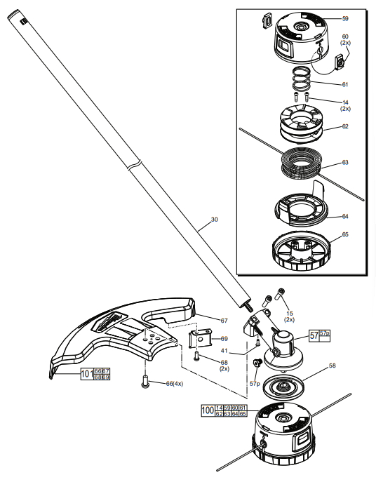
| FIG | PART NO. | DESCRIPTION OF PART NO. REQ. | |
| 14 | 05-88-1200 | M4 x 16mm Pan Hd. ST 1-20 Screw | (2) |
| 15 | 05-74-0015 | M6 x 21.5mm, 5mm Hex Socket Cap Screw | (2) |
| 30 | 45-08-0028 | Drive Shaft Assembly (For String Trimmer) | (1) |
| 41 | 05-81-0131/. | M6 x 18mm, 5mm Hex Socket Cap Screw | (1) |
| 57 | 14-29-0038 | Gearbox Assembly | (1) |
| 57 | 05-85-0080 | M8 x 1 25 Hex Hd. Screw | (1) |
| 58 | 44-66-0139 | Lock Plate Assembly | (1) |
| 59 | ————— | — Trimmer Head Body | (1) |
| 60 | ————— | Guideline Eyelets | (2) |
| 61 | ————— | Trimmer Head Spring | (1) |
| 62 | ————— | Spool | (1) |
| 63 | ————— | 0.080″ x 150′ String | (1) |
| 64 | ————— | Trimmer Head Ring | (1) |
| 65 | ————— | Trimmer Head Bump Cap | (4) |
| 66 | 05-81-0132 | M6 x 14mm Pan Hd. T-30 Machine Screw | (1) |
| 67 | ————— | String Trimmer Guard | (1) |
| 68 | 05-74-0935 | M5 x 15mm Pan Hd. T-25 Machine Screw | (2) |
| 69 | 42-26-0024 | Line Cut-Off Blade | (1) |
| 100 | 49-16-2714 | Loaded Replacement Head | (1) |
| 101 | 14-32-001210-20-1781 | String Guard AssemblyWarning Label (Not Shown) | (1)(1) |
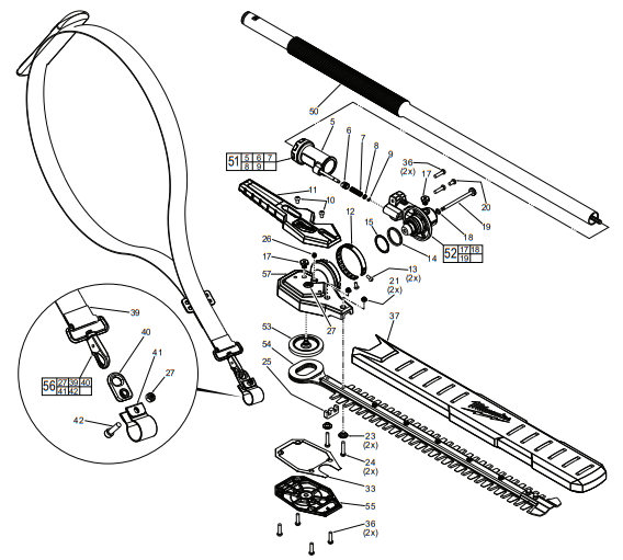
No. 49-16-2719 Hedge Trimmer Attachment
| FIG. | PART NO. | DESCRIPTION OF PART | NO. REQ. |
| 5 | — Handle with Locking Pin | (1) | |
| 6 | 06-38-0021 | Threaded Stud | (1) |
| 7 | 40-50-0114 | Lock Pin Spring | (1) |
| 8 | 45-88-0078 | Flat Washer | (1) |
| 9 | 34-60-0023 | C Retaining Ring | (1) |
| 10 | 05-78-0029 | M5 x 8mm Pan Hd. T-25 Machine Screw | (2) |
| 11 | 31-44-0127 | Hedge Trimmer Handle | (1) |
| 12 | 42-16-0011 | Detent Band | (1) |
| 13 | 05-78-0038 | M4 x 7mm Pan Hd. 1-20 Machine Screw | (2) |
| 14 | 34-40 0126 | 0-Ring | (1) |
| 15 | 45-88-0079 | Flat Washer | (1) |
| 17 | 05-85-0080 | M8 x 1.25 Hex Hd. Screw | (2) |
| 18 | 34-40 4002 | 0-Ring | (1) |
| 19 | 44-60-0069 | Gear Alignment Pin | (1) |
| 20 | 05-78-0024 | M5 x 10mm Pan Hd. T-25 Machine Screw | (1) |
| 21 | 05-55-0019 | M5 Nylon Hex Nut | (2) |
| 23 | 42-40-0123 | Bushing | (2) |
| 24 | 05-78-0019 | M5 x 26mm Pan Hd. T-25 Machine Screw | (2) |
| 25 | 45-06-0016 | Felt Seal | (1) |
| 26 | 06-83-0017 | M6 x 8mm Cone Point Set Screw | (1) |
| 27 | 06-57-0625 | M5 Nylon Insert Hex Nut | (2) |
| 33 | 43-44-0026 | Gasket | (1) |
| 36 | 05-78-0033 | M5 x 20mm Pan Hd. T-25 Machine Screw | (6) |
| 37 | 49-62-0011 | Blade Sheath | (1) |
| 39 | Shoulder Strap | (1) | |
| 40 | 44-66-0039 | Shoulder Strap Mounting plate | (1) |
| 41 | 45-56-0011 | Shoulder Strap Mounting Band | (1) |
| 42 | 05-74-0015 | M6 x 21.5mm Cap Hd. T-30 Machine Screw | (1) |
| 50 | 45-08-0023 | Drive Shaft Assembly (For Hedge Trimmer) | (1) |
| 51 | 14-34-0011 | Handle Assembly with Locking Pin | (1) |
| 52 | 14-29-0014 | Gearbox Assembly | (1) |
| 53 | 14-29-0015 | Gear/Crankshaft Assembly | (1) |
| 54 | 42-26-0016 | Blade Assembly | (1) |
| 55 | 31-15-0067 | Gearbox Cover with Ball Bearing | CI ) |
| 56 | 45-56-0012 | Shoulder Strap Assembly | (1) |
| 57 | 43-76-2719 | Hedge Trimmer Housing Assembly | (1) |
| 10-20-1783 | Warning Label (Not Shown) | (1) |
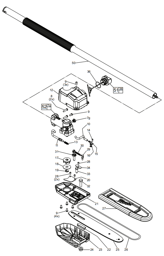
No. 49-16-2721 Extension Tube Attachment
| FIG. | PART NO. | DESCRIPTION OF PART NO. REQ. | |
| 7g | 05-85-0080 | M8 x 1.25 Hex Head Screw | (1) |
| 8 | 05-78-0033 | M5 x 20mm Pan Hd. T-25 Machine Screw | (2) |
| 9 | 05-78-0024 | M5 x 10mm Pan Hd. T-25 Machine Screw | (8) |
| 10 | 45-36-0016 | Outlet Tube | (1) |
| 11 | 45-76-0011 | Inlet Tube | (1) |
| 12 | 45-66-0013 | Oil Tank Assembly | (1) |
| 13 | 40-50-9220 | Cone Spring | (1) |
| 14 | 05-81-0015 | M3 x 6mm Pan Hd. Phillips Screw | (1) |
| 15 | 42-86-0012 | Connector | (1) |
| 16 | 34-40-4002 | 0-Ring | (1) |
| 17 | 45-44-0010 | Sprocket | (1) |
| 18 | 45-88-7001 | Chain Washer | (1) |
| 19 | 42-70-5268 | Retaining E-Ring | (1) |
| 20 | 43-74-0011 | Hook | (1) |
| 21 | 42-92-0057 | Bar Mount Housing | (1) |
| 22 | 43-84-0013 | Insert Block | (1) |
| 23 | 43-72-0014 | Bar Holder | (1) |
| 24 | 05-55-5001 | 13mm M8 Flange Nut | (1) |
| 25 | 48-09-5001 | 10″ Bar | (1) |
| 26 | 49-16-2723 | 10″ Chain, 3/8″ Pitch | (1) |
| 27 | 49-62-0015 | Scabbard | (1) |
| 28 | 05-78-0038 | M4 x 7mm Pan Hd. T-20 Machine Screw | (3) |
| 29 | 05-89-0017 | Chain Tensioning Post | (1) |
| 30 | 05-89-0018 | Chain Tensioner Main Screw | (1) |
| 31 | 05-81-9001 | Chain Tensioner Adjustment Screw | (1) |
| 32 | 05-85-0012 | M8 x 28mm Hex Head Machine Screw | (1) |
| 33 | 44-50-0015 | Locating Pin | (1) |
| 34 | 44-66-0089 | Plate | (1) |
| 36 | 34-40-9002 | Oil Cap 0-Ring | (1) |
| 50 | 45-08-0029 | Drive Shaft Assembly (For Pole Saw) | (1) |
| 51 | 42-52-3001 | Oil Cap Assembly | (1) |
| 52 | 14-29-0016 | Gearbox Assembly | (1) |
| 10-20-1784 | Warning Label (Not Shown) | (1) |
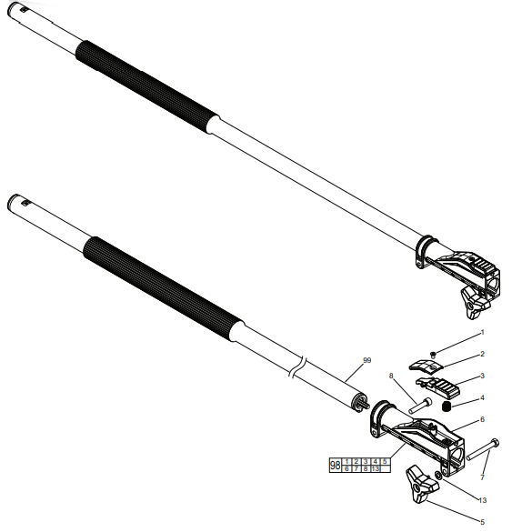
|
FIG. |
PART NO. | DESCRIPTION OF PART |
NO. REQ. |
| 1 | 05-81-0592 | M4 x 6.5mm Flat Head T-15 Screw | (1) |
| 2 | 42-92-0047 | Trigger Cover | (1) |
| 3 | 45-72-0013 | Quick Change Trigger | (1) |
| 4 | 40-50-1090 | Spring | (1) |
| 5 | 44-60-0068 | Clamping Knob | (1) |
| 6 | ————— | Quick Release Casting | (1) |
| 7 | 05-78-0027 | M6 x 50mm Hex Hd. Machine Screw | (1) |
| 8 | 05-74-0026 | M6 x 30mm Cap Hd. Hex Socket Screw | (1) |
| 13 | 45-88-0011 | Flat Washer | (1) |
| 98 | 14-02-0010 | Quick Release Assembly | (1) |
| 99 | 45-08-0033 | Drive Shaft Assembly (For Extension) | (1) |
SERVICE WIRING DIAGRAM

References
[xyz-ips snippet=”download-snippet”]