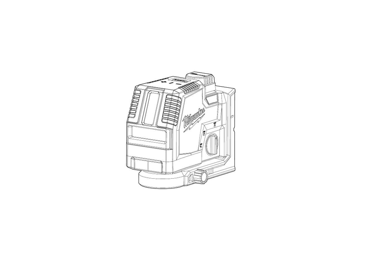
milwaukee REDLITHIUM USB CROSS LINE LASER User Manual
 WARNING
 To reduce the risk of injury, user must read and understand operator’s manual.
GENERAL POWER TOOL SAFETY WARNINGS
WARNING Read and understand all instructions. Failure to follow all instructions listed below may result in electric shock fire and or serious personal injury. Save all warnings and instructionsfor future reference.
- Save these instructions – This operator’s manual contains important safety and operating instructions
LASER SAFETY
WARNING The device produces visible laser beams, which are emitted from the tool.
- This device complies with AS/NZS 1, Class 2 Laser.
- Laser light – Do not stare into beam or view directly with optical instruments. Do not point laser light at others. Laser light can cause eye
PERSONAL SAFETY
- Do not allow persons unfamiliar with the tool, these safety instructions, and the tool’s opera- tor’s manual to operate the This tool can be dangerous in the hands of untrained users.
- Do not Keep proper footing and balance at all times. This enables better control of the tool in unexpected situations.
BATTERY USE AND CARE
- USE AND CHARGE ONLY REDLITHIUM® USB BATTERIES IN THIS USB RECHARGEABLE OTHER TYPES OF BATTERIES MAY CAUSE PERSONAL INJURY AND DAMAGE.
- BEFORE USING THE BATTERY AND TOOL, READ THIS OPERATOR’S MANUAL AND ALL LABELS ON THE BATTERY AND
- USE ONLY WITH LISTED/CERTIFIED ITE POWER SUPPLY. Others may result in a risk of fire, electric shock or personal
- CHARGE IN A WELL VENTILATED AREA. Do not block charger Keep them clear to allow proper ventilation. Do not allow smoking or open flames near a charging battery. Vented gases may explode.
- MAINTAIN CORD. When unplugging charger, pull plug rather than cord to reduce the risk of damage to the electrical plug and Never carry charger by its cord. Keep cord from heat, oil and sharp edges. Make sure cord will not be stepped on, tripped over or subjected to damage or stress. Do not use charger with damaged cord or plug. Have a damaged charger replaced immediately.
- USE ONLY RECOMMENDED ATTACHMENTS. Use of an attachment not recommended or sold by the battery charger or battery manufacturer may result in a risk of fire, electric shock or personal
- TO REDUCE THE RISK OF ELECTRIC SHOCK, always unplug charger before cleaning or
- DO NOT BURN OR INCINERATE BATTERY Battery may explode, causing personal injury or damage. Toxic fumes and materials are created when battery are burned.
- DO NOT CRUSH, DROP, OR DAMAGE battery. Do not use a battery or charger that has received a sharp blow, been dropped, run over, or damaged in any way (e.g., pierced with a nail, hit with a hammer, stepped on).
- DO NOT DISASSEMBLE. Incorrect reassembly may result in the risk of electric shock, fire or exposure to battery chemicals. If it is damaged, take it to a MILWAUKEE® service
- BATTERY CHEMICALS CAUSE SERIOUS Never allow contact with skin, eyes, or mouth. If a damaged battery leaks battery chemicals, use rubber or neoprene gloves to dispose of it. If skin is exposed to battery fluids, wash with soap and water and rinse with vinegar. If eyes are exposed to battery chemicals, immediately flush with water for 20 minutes and seek medical attention. Remove and dispose of contaminated clothing.
- DO NOT SHORT CIRCUIT. A battery pack will short circuit if a metal object makes a connection between the positive and negative contacts on the battery pack. Do not place a battery pack near anything that may cause a short circuit, such as coins, keys or nails in your pocket. Do not allow fluids to flow into battery Corrosive or conductive fluids, such as seawater, certain industrial chemicals, and bleach or bleach containing products, etc., can cause a short circuit. A short circuited battery pack may cause fire, personal injury, and product damage.
- Store your battery and tool in a cool, dry place. Do not store battery where temperatures may exceed 50°C (120°F) such as in direct sunlight, a vehicle or metal building during the summer.
SPECIFIC SAFETY RULES FOR LASERE LEVELS
- Do not dispose of tool or batteries together with household waste material! Tool and batteries that have reached the end of their life must be collected separately and returned to an environmentally compatible recycling facility.
- Maintain labels and nameplates. These carry important information. If unreadable or missing, contact MILWAUKEE® for a replacementCAUTION Use of controls or adjustments or performance of procedures other than those specified herein may result in hazardous radiation exposure
- Be sure to power off instrument after use. When instrument will not be used for a long period, place it in storage after removing batteries
- Always use common sense and be cautious when using tools. It is not possible to anticipate every situation that could result in a dangerous Do not use this tool if you do not understand these operating instructions or you feel the work is beyond your capability; contact Milwaukee Tool or a trained professional for additional information or training.
ADDITIONAL BATTERY SAFETY RULES
WARNING To reduce the risk of fire, personal injury, and product damage due to a short circuit, never immerse your tool, battery pack or charger in fluid or allow a fluid to flow inside them. Corrosive or conductive fluids, such as seawater , certain industrial chemicals, and bleach or bleach-containing products, etc., can cause a short circuit.WARNING Do not charge non-rechargeable batteries.
SYMBOLOGY
![]() Volts
Volts
![]() Direct Current
Direct Current
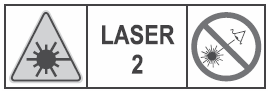 LASER RADIATION DO NOT STARE INTO BEAM CLASS 2 LASER PRODUCT
 Universal Serial Bus (USB)
 Magnets
 Read operator’s manual
 Amps
Amps
 Regulatory Compliance Mark (RCM). This product meets applicable regulatory requirements.
 Do not dispose of electric tools together with household waste material. Electric tools and electronic equipment that have reached the end of their life must be collected separately and returned to an environmentally compatible recycling facility.
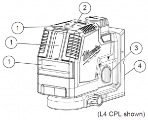
FUNCTIONAL DESCRIPTION
- Laser apertures
- Laser mode indicator
- ON /OFF Dial
- Pivot Bracket
- Battery compartment
- Fuel gauge
- Micro adjust
- USB power outlet
- USB power inlet
- Magnets

SPECIFICATIONS
Cross Line L4 CLLCross Line and Plumb Points L4 CPLUSB Input Volts 5V DCUSB Input Amps 0.1 – 2.1 AOutput Volts 4V DCOutput Amps 2.1 A
REDLITHIUM® USB Batteries
Volts 4V DCPower Supply Cat. No 4931 4605 95ALaser Class 2 Lines Max Power PAVG 7 P:Points Max Power. PAVG 1 P:Frequency 10 KHzPulse Duration Normal Mode TP 70 VPulse Duration Power Save. TP 50 VWavelength 510-530 nmMax. altitude 2000 mRelative air humidity max 80%Lines Beam Divergence 1 radPoints Beam Divergence 0.5 mradStorage Temp 20°C to 50°CWorking Range 30mRange with Detector 50mAccuracy ±3.18 mm over 10 mmSettle Time < 3 SecondsTripod Mount 1/4″-20Ingress Protection P54Impact Resistant 1 mLeveling Auto ±°4 side to side, front to backOperating TemperatureBattery and Charger -5°C to 40°CBattery and Tool -10°C to 40°C
BATTERY
WARNING To reduce the risk of fire, personal injury, and product damage due to a short circuit, never immerse your tool, battery as seawater, certain industrial chemicals, and bleach or bleach containing products, etc., can cause a short circuit.
Maintenance and Storage
Do not expose your battery or cordless tools to water or rain, or allow them to get wet. This could damage the tool and battery. Do not use oil or solvents to clean or lubricate your battery. The plastic casing will become brittle and crack, causing a risk of injury. Store batteries at room temperature away from moisture. Do not store in damp locations where corrosion of terminals may occur. As with other battery types, permanent capacity loss can result if the pack is stored for long periods of time at high temperatures (over 50°C (120°F)). MILWAUKEE® Li-Ion batteries maintain their charge during storage longer than other battery types. After about a year of storage, charge the battery as normal.
WARNING To reduce the risk of injury or ex- plosion, never burn or incinerate a battery pack even if it is damaged, dead or com- politely discharged. When burned, toxic fumes and materials are created.
Disposing of MILWAUKEE® Li-Ion Battery
MILWAUKEE® Li-Ion batteries are more environmentally friendly than some other types of power tool batteries. Always dispose of your battery according to federal, state and local regulations. Contact a recycling agency in your area for recycling locations. Even discharged batteries contain some energy. Before disposing, use electrical tape to cover the terminals to prevent the battery from shorting, which could cause a fire or explosion.
ASSEMBLY
WARNING use and charge only REDLITHIUM® USB batteries in this USB re- chargeable tool. Other types of batteries may cause personal injury and damage.
Inserting the Battery
- Twist the battery cap and
- Line up the arrow on the battery with the arrow in the compartment and fully insert the
- Replace the cap and twist to
Charging the Battery
When the tool is turned on under battery power only, the remaining battery life is indicated: Green Solid: 50-100% remaining Yellow Solid: 11-49% remaining Red Solid: 3-10% remaining Red Flashing: 0-3% remaining LOW POWER MODE To indicate LOW POWER MODE, the laser beams will dim, and the green laser mode indicator pulse, and the laser beams will blink quickly 3 times, fol- lowed by 4 seconds of solid on (repeating). Charge the battery.
To charge the battery:
- Connect your USB cable to a suitable power source such as an AC USB wall adaptor, computer, or USB
- Lift the rubber cover to expose the micro USB Insert the micro USB plug into the micro USB port. Users may experience longer charge times from laptops and other power sources.
- When the laser level is charged when OFF, the indicator light will display the charging status: Pulsing Red: Charging, 0-49% charged Pulsing Yellow: Charging, 50-99% charged Solid Green: 100% Charged. Flashing Red/Green: If the indicator light flashes Red/Green continuously, the battery is either not inserted correctly; too hot or too cold; or the battery is faulty or damaged. Check that the battery is fully seated into the bay. Remove the battery and reinsert. If the light continues to flash red and green, the battery may betoo hot or too cold, or damaged. Allow the battery to cool down, warm up, or dry out and then reinsert. If the problem persists, contact a MILWAUKEE® service facility.
WARNING To reduce the risk of injury or dam- age, securely mount/attach the laser before starting an operation. Injury/damage may occur if the laser falls.
Mounting/Adjusting the Laser Level
The pivot bracket can be used to mount the laser level in multiple ways:
- Use the embedded magnets to secure the laser level to framing steel studs, steel beams, etc.
- Use the keyhole slot to hang the laser level on the wall with a nail or screw
- Position the laser and/or wall mount on a stable
- Use the 1/4″ – 20 threaded insert to mount on a standard tripod with a corresponding mounting
- Once the level is mounted, use the micro adjustment
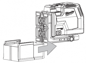
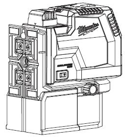
Attaching/Removing the Riser (L4 CPL)
use of the bottom plumb point, such as clearance over steel stud track. To attach the riser, slide the riser onto the pivot bracket from the rear until it locks into place. To remove the riser, hold the laser securely and formally push the riser from the front.
OPERATION
WARNING To reduce the risk of injury or temporary effect on vision, do not look directly into the laser when it is on.
COUTION Use of controls or adjustments or performance of procedures other than those specified herein may result in hazardous radiation exposure.
NOTICE Perform the Accuracy Field Check procedure immediately upon unboxing vof each new Laser Level and before exposure to jobsite conditions. See “Accuracy Field Check” for information.TURNING OFF/ ON To turn on the laser and unlock the pendulum, rotate the On/Off dial to the desired position. The remaining battery life will be displayed.WARNING Do not look directly into laser apertures. Laser Mode Indicator LED will display, and horizontal level line will immediately be emitted from aperture in the laser housing.
![]() Turns ON the laser and unlocks the pendu- lum to enable self-leveling.
Turns ON the laser and unlocks the pendu- lum to enable self-leveling.![]() Turns ON the laser but does not unlock the pendulum (self leveling is disabled). The to indicate that the projected lines are not level or plumb.NOTICE: The
Turns ON the laser but does not unlock the pendulum (self leveling is disabled). The to indicate that the projected lines are not level or plumb.NOTICE: The ![]() mode disables self- leveling and therefore is not intended for projecting a level or plumb line.
mode disables self- leveling and therefore is not intended for projecting a level or plumb line.![]() Turns OFF the laser and locks the pen- and store the Laser Level in the protective carrying case.
Turns OFF the laser and locks the pen- and store the Laser Level in the protective carrying case.
Use the MODE button to cycle through the three laser modes:
![]() Horizontal Level Line
Horizontal Level Line
![]() Vertical Plumb Line
Vertical Plumb Line
![]() Perpendicular Level & Plumb Lines **
Perpendicular Level & Plumb Lines **
The green laser mode indicators will display the selected mode.
** Plumb points on Cat. No. 3522-20 only
Power Save
To put the tool into power save mode and extend the run time by dimming the laser, press and hold the MODE button for 3 seconds. Visual range is decreased in power save mode. Pressing MODE again for 3 seconds will deactivate power save if battery level is above 3%.
Using the Laser Level
1. For best results, place the tool on a work surface that is:
- sturdy
- level (within 4 degrees of true level)
- free of vibrations
- 90° to the work area
2 Turn on the tool.3. The tool will self-level when placed on surfaces within 4 degrees of true level.4. The tool is ready once the emitted lines are continuous and no longer moving on the work surface.5 If the tool cannot achieve a level state (i.e., the work surface is > 4 degrees off true level), the laser points will flash rapidly (3 flashes per second). Relocate or adjust the work surface.
Troubleshooting
If the tool does not turn on:
- Ensure battery is installed properly. Fuel gauge should indicate remaining charge when correctly installed.
- Ensure battery is charged.
- Ensure the tool’s internal temperature is within specified operating ranges. If stored in excessive heat or cold, allow at least 2 hours to an appropriate ambient temperature between -10°C to 40°C before turning on the tool.
If problem persists, please contact a MILWAUKEE® service facility for support.
ACCURACY FIELD CHECK
NOTICE Perform the Accuracy Field Check procedure immediately upon unboxing of each new Laser Level and before exposure to jobsite conditions. See “Accuracy Field Check” for information. Should any deviation from listed product accuracy be found, please contact a MILWAUKEE® service facility. Failure to do so could result in rejection of warranty claim. Ambient temperature gradients can impact laser accuracy. For accurate and repeatable results, the following procedure should be conducted with the laser elevated off the ground and placed in the centre of the working area. Abusive treatment of the Laser Level, such as excessive impacts from repeated or high drops, can also lead to deviations in product accuracy. Therefore, it is recommended to conduct the Accuracy Field Check procedure after any impact or before completing any critical jobs.
Horizontal Height Accuracy
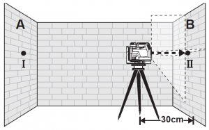
A free measuring distance of approximately 20m on a firm surface between two walls or structures (indicated as ‘A’ and ‘B’ below) is required for this check. It is also suggested to mount the Laser Level to a an appropriate tripod for easy adjustment.
- .Securely mount the tool within 30cm of wall ‘A’ as shown below.
- Turn the tool to ON and to Perpendicular Level & Plumb Lines Mode.
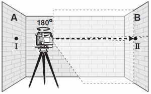
- Direct the front laser beam against the nearest wall A and allow to self-level. Mark the centre of the laser cross on the wall (point I).
- Rotate the tool 180° without changing the height, allow it to self-level, and mark the centre of the laser cross on the opposite wall B (point II)
- Move the tool within 30cm of wall B. Allow the laser to self level. Align the laser cross in the general direction of point II on wall B.
- Adjust the height of the tool (using the tripod or by adding shims, if required) to align the laser cross directly onto point II on wall B. Allow the tool to self-level.
- Rotate the tool 180° without changing the height, allow it to self-level, and mark the centre of the laser cross on wall A (point III). Point III should be aligned as vertically above or below point I on wall A as possible
- The distance between points I and III on wall A is the height deviation (d) of the tool. This distance should not exceed 3.18mm (max.) at 10m (12.72mm at 40m). For the Measuring distance of 2 x 20m = 40m, the maximum allowable deviation (d) is: 40m x ±3.18mm ÷ 10m = ±12.72mm

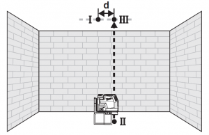
Horizontal Leveling Accuracy
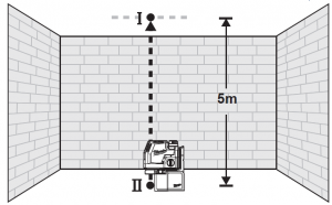
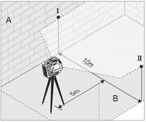
A free measuring space of approximately 10m (33′) x 10m (33′) on a firm surface between two walls or structures A and B is required for the check. It is also suggested to mount the Laser Level to a commercially available Tripod for easy adjustment. Securely mount the tool on one side of the room and centered between walls A and B. Direct the laser lines toward the other side of the room such that the horizontal line appears on both walls A and B. Allow the laser to Self-Level
- Turn the tool to ON and to Horizontal Level Line mode.
- At a distance of 5m from the laser, mark the centre of the horizontal line on Wall A (Point I). Do the same on Wall B (Point II).
- Move the Laser 10m toward the opposite wall and rotate the laser 180°. Allow the laser to Self-Level.
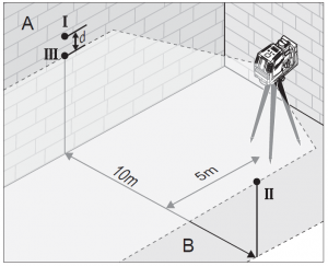
- Adjust the height of the tool (using the tripod or by adding shims, if required) such that the center of the horizontal line is projected exactly against the previously marked point II on wall B. Ensure the Laser is self-leveled after
- Mark the center of horizontal line on wall A (point III). Take care that point III is aligned as vertical as possible above or below point
- The distance d between marked points I and III on wall A indicates the actual deviation (d) of the
- For the Measuring distance of 2 x 10m = 20m, the maximum allowable deviation (d) is: 20m x ±3.18mm ÷ 10m = ±6.36mm Thus, the difference d between points I and III should not exceed 6.5mm (max.) at 20m.
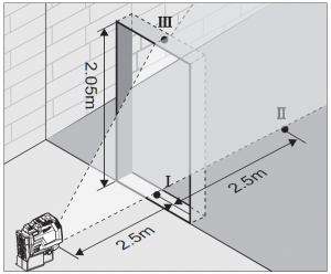
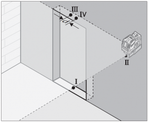
Vertical Leveling Accuracy
A door opening with approximately 2.5m of space on each side of the opening is required for this
-
- Securely mount the tool 2.5m from one side of the door opening
- Turn the tool to ON and to Vertical Plumb Line
- Position the tool with the laser towards the door Allow the tool to self-level.
- Mark the centre of the vertical laser line on the floor in the middle of the door opening (point I), at a distance of 2.5m (8′) beyond the door opening (point II), and at the upper edge of the door opening (point III).
- Move the laser level directly behind point II on the other side of the door. Align the vertical laser line so the center is directly aligned with points I and
- Mark the center of the vertical line at the upper edge of the door opening (point IV).
- Measure the height of the door
-
- The maximum vertical deviation (d) is: d max = 2X H (door opening) x ±3.18mm ÷ 10m Example: for a door opening height of 2.05m, the maximum permitted deviation (d) is: d max = 2 x 2.05m x ±3.18mm ÷ 10m = ± 1.3mm Therefore, the measurement between points III and IV on the upper door opening should not exceed 1.3mm in a 2.05m doorway.
Plumb Dot Accuracy (L4 CPL)
A free measuring distance of approximately 10m (33′) between floor and ceiling on a firm surface is required for this check. It is suggested to install riser block, if not already equipped.
- Place the tool within 30cm of the Turn the tool to ON and to Perpendicular Level & Plumb Lines Mode.
- Set tool on ground and mark the centre of the plumb point on the ceiling (point I). Also, mark the center of the plumb point on the floor (point II).
- Rotate the tool 180°. Align the centre point of the
- Mark the center of the top plumb point on the reference line on the ceiling (point III).
- The distance between points I and III on the ceiling is the deviation (d) of the This distance should not exceed 3.18mm (max.) at 10m. For the Measuring distance of 2 x 5m = 10m, the maximum allowable deviation (d) is: 10m x ± 3.18mm ÷ 10m = ±3.18mm

MAINTENANCE
WARNING reduce the risk of injury, always remove the battery before performing any maintenance. Never disassemble the tool.
Maintain Laser Level
Maintain tools. If damaged, have the tool repaired before use. Accidents may be caused by poorly maintained tools.
WARNING To reduce the risk of personal injury and damage, never immerse them.
Cleaning
Keep tool handles clean, dry and free of oil or grease. Use only mild soap and a damp cloth to clean the tool since certain cleaning agents and solvents are harmful to plastics and other insulated parts. Some of these include gasoline, turpentine, lacquer thin- ner, paint thinner, chlorinated cleaning solvents, ammonia and household detergents containing am- around tools.
Cleaning the Lenses
Blow off loose particles with clean compressed Air Carefully wipe the surface with a cotton swab moistened with water.
Repairs
This tool has limited serviceable parts. Do not open housing or disassemble tool. For repairs, return the tool, battery pack and charger to the nearest authorized service center.
ACCESSORIES
WARNING Use tools only with specifically designated accessories. Use of any other accessories may create risk of injury.
WARRANTY – AUSTRALIA and NEW ZEALAND
Please refer to Australian and New Zealand warranty supplied with tool. This warranty applies only to product sold by authorised dealers in Australia and New Zealand.
SERVICE – AUSTRALIA and NEW ZEALAND
MILWAUKEE® prides itself in producing a premium quality product that is Nothing But Heavy DutyTM. Your satisfaction with our products is very important to us! If you encounter any problems with the operation of this tool, please contact your authorised MILWAUKEE® dealer.For a list of MILWAUKEE® dealers, guarantee or service agents please contact MILWAUKEE® Customer Service or visit our website. (Australia Toll Free Telephone Number 1300 645 928) (New Zealand Toll Free Telephone Number 0800 645 928) or visit milwaukeetool.com.au/milwaukeetool.co.nz.
Milwaukee Electric Tool Corporation13135 West Lisbon Road, Brookfield, Wisconsin U.S.A. 53005
Milwaukee Tool (Australia)
21 Kelletts Road, Rowville, VIC 3178 Melbourne, AustraliaMilwaukee Tool (New Zealand) 274 Church Street, Penrose, Auckland, 1061, New ZealandDESIGNED BY MILWAUKEE ELECTRIC TOOL CORP. PROFESSIONALLY MADE IN CHINA PRINTED IN CHINA
Read More About This Manual & Download PDF:
[xyz-ips snippet=”download-snippet”]