![]()
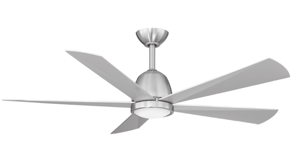
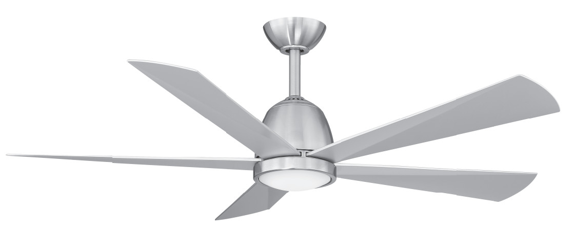
GaleventiREAD AND SAVE ALL INSTRUCTIONS52″ Ceiling Fan for Indoor Location
INSTRUCTION MANUAL WARRANTY CERTIFICATE
02020Minka LigMing, Inc. Manual design and all elements of manual design are protected by U.S. Federal and/or State Law, including Patent, Trademark, and/or copyright laws.1151 W. Bradford Court, Corona, CA 92882 • For Customer Assistance Call: 1-800-307-3267

WARRANTY
The Minka warranty Is for one (1) year from the date of purchase from an authorized Minka dealer. This warranty Is only valid to the original purchaser or user against all defects In material and workmanship (light bulbs excluded) for one (1) full year. Additionally, Minka warrants the motor only for the lifetime of the Minka ceiling fan (excluding wall controls and electrical components), to the original purchaser or user.
- The warranty is void with the use of any non-Minka electrical devices; e.g., wall controls or electrical dimmer switches, etc.
- The warranty Is void once the original purchaser or user ceases to own the fan or the fan Is moved from its original point of installation.
- The warranty Is void with the use of any hanger bracket (non-Minka or non-fan specific) other than the hanger bracket supplied in the box.
- The warranty is void if installed in an environment other than its intended use (Indoor fans installed outdoors or in a covered outdoor patio area, or subjected to environmental conditions: salt air, humidity, direct sun exposure, etc.). Outdoor finishes are specifically excluded from the terms of this warranty since they are subject to environmental and maintenance damages beyond our control.
WARRANTY SERVICE INFORMATIONTo obtain warranty service during the warranty period, the purchaser should return the fan with the original sales receipt to the original place of purchase. Replacement is subject to the availability of the same model. This is a limited warranty; the original purchaser or user is responsible for the cost of removal and re-installation of repaired or replacement products. Outdoor finishes are specifically excluded from the terms of this warranty since they are subject to environmental and maintenance damages beyond our control. Fan warranty registration should be mailed as addressed on the warranty card.
Date Purchased……….Serial Number…………Store Purchased………………… Model Numbe: 84035/84036/84037
SAFETY RULES
- To reduce the risk of electric shock, insure electricity has been turned off at the circuit breaker or fuse box before beginning.
- All wiring must be in accordance with the National Electrical Code “ANSI/NFPA 70-1999” and local electrical codes. Electrical installation should be performed by a qualified licensed electrician.
- The outlet box and support structure must be securely mounted and capable of reliably supporting a minimum of 35 lbs. Use only UL-listed outlet boxes marked “FOR FAN SUPPORT.”
- The fan must be mounted with a minimum of 7 ft. clearance from the trailing edge of the blades to the floor.
- Avoid placing objects in the path of the blades.
- To avoid personal injury or damage to the fan and other items, be cautious when working around or cleaning the fan.
- Do not use water or detergents when cleaning the fan or fan blades. Dry dust cloth or lightly dampened cloth will be suitable for most cleaning.
- After making electrical connections, spliced conductors should be turned upward and pushed carefully up into the outlet box. The wires should be spread apart with the grounded conductor and the equipment-grounding conductor on one side of the outlet box and the ungrounded conductor on the other side of the outlet box.
- All setscrews must be checked and retightened where necessary before installation.
- Turn the fan off and wait for the blades to stop completely before performing any maintenance or cleaning.
NOTE: The important safeguards and instructions appearing in this manual are not meant to cover all possible conditions and situations that may occur. It must be understood that common sense, caution and care are factors that cannot be built into this product These factors must be supplied by the person (s) installing, caring for and operating the unitWARNINGTO REDUCE THE RISK OF FIRE, ELECTRIC SHOCK, OR OTHER PERSONAL INJURY, MOUNT FAN ONLY ON AN OUTLET BOX OR SUPPORTING SYSTEM MARKED ACCEPTABLE FOR FAN SUPPORT OF 35 LBS (15.9 KG) OR LESS AND USE MOUN11NG SCREWS PROVIDED WITH THE OUTLET BOX. MOST OUTLET BOXES COMMONLY USED FOR THE SUPPORT OF LIGH11NG FIXTURES ARE NOT ACCEPTABLE FOR FAN SUPPORT AND MAY NEED TO BE REPLACED. CONSULT A QUALIFIED ELECTRICIAN IF IN DOUBT.TO REDUCE THE RISK OF PERSONAL INJURY, DO NOT BEND THE BLADE HOLDERS WHILE INSTALLING, BALANCING THE BLADES, OR CLEANING THE FAN. DO NOT INSERT FOREIGN OBJECTS BETWEEN ROTATING FAN BLADES.TO REDUCE THE RISK OF FIRE OR ELECTRONIC SHOCK, THIS FAN ONLY CAN USE DL-1167RYS-02 SOLID-STATE SPEED CONTROL WITH R-41035 REMOTE CONTROL ONLY.
PACKAGE CONTENTS
Unpack your fan and check the contents. You should have the following items:
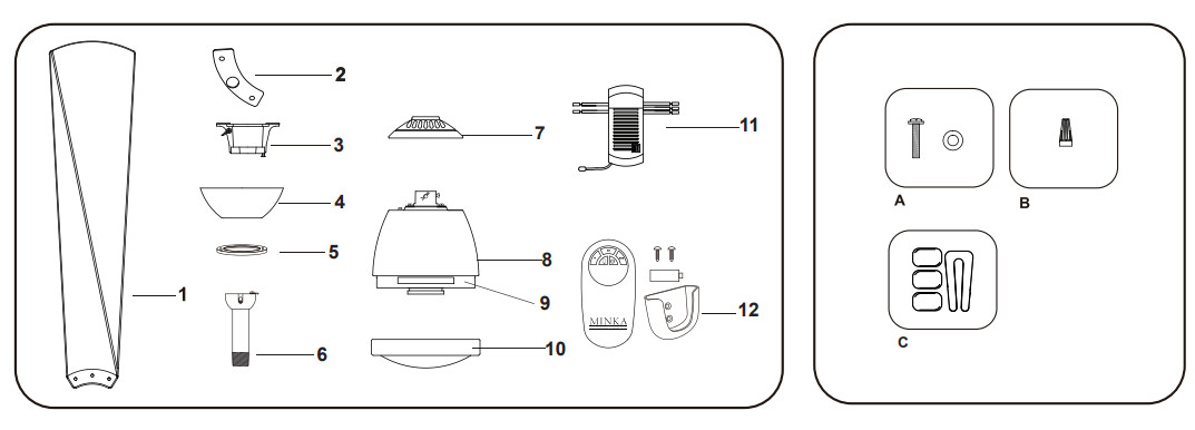
- Fan blades (5)
- Blade holder (5)
- Hanger bracket
- Canopy
- Canopy cover
- Standard download assembly(6″)
- Coupling cover
- Fan motor assembly
- Flywheel (preassembled) (1)
- 16W LED assembly
- Receiver(1) + wire nut (6)
- Transmitter + holder + 2 mounting screws + 12 V battery
A. Blade attachment hardware: 3/6″ x 18mm blade screw ( 15 + 1 spare) ,Fiber washer ( 15 + 1 spare)B. Wire nut (3)C. Balancing kit
INSTALLING THE FAN
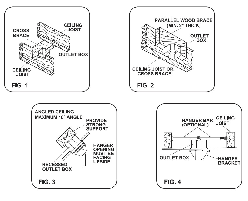
Toots Required: Phillips screwdriver, slotted screwdriver; step-ladder, wire cutters; electrical tape.MOUNTING OPTIONSIf there isn’t an existing mounting box, then read the following instructions. Disconnect the power by removing fuses or turning off circuit breakers.Secure the outlet box directly to the building structure. Use appropriate fasteners and building materials. The outlet box and its support must be able to fully support the moving weight of the fan (at least 35 lbs.). Use a UL Listed metal outlet box. Do not use a plastic outlet box.Figures 1, 2, and 3 are examples of different ways to mount the outlet box.Note: You may need a longer downlrod to maintain proper blade clearance when Installing on a steep, sloped ceiling. Longer downloads are available from your Minka dealer.To hang your fan where there is an existing fixture but no ceiling Joist, you may need to install a hanger bar as shown in Fig. 4 (available at your Minka dealer).
HANGING THE FAN
WARNING: All of the parts, hardware, and components such as the hanger bracket and hanger ball have been provided for your safety and the proper installation of your new ceiling fan. The use of other parts, hardware or components not supplied by Minka with the fan will void the Minka Warranty. REMEMBER to turn off the power. Follow the steps below to hang your fan properly:Step 1. Secure the Hanger Bracket to the ceiling outlet box using the screws provided with your outlet box in conjunction. (Fig. 5)Step 2. Loosen the two Set Screws and remove the Hitch Pin and Lock Pin from the coupling located on The top of the Motor Assembly. (Fig.6)Step 3. Remove the Hanger Ball from the Downrod Assembly by loosening the Set Screw and removing the Cross Pin. (Fig.7) Step 4. Carefully feed fan wires up through the downlrod. (Fig. 8 ) Thread Downrod into the Coupling until the holes are lined up and secure with the Lock Pin and Hitch Pin previously removed, tighten Set Screws. (Fig. 9) Step 5. Slip coupling cover, canopy cover, and canopy onto downlrod. (Fig. 9 ) Carefully reinstall hanger ball onto rod being sure that cross pin is in the correct position, set screws are tightened and wires are not twisted.Step 6. Lift the Motor Assembly and place The Hanger Ball into the Hanger Bracket. Rotate the Motor Assembly as needed until the check groove from the Hanger Ball seats firmly over the registration slot from the Hanger Bracket. (Fig.10)

ELECTRICAL CONNECTIONS
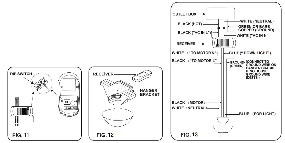
WARNING: To avoid possible electrical shock be sure electricity is turned off at the main fuse or breaker box before wiring. NOTE: This remote control unit is equipped with 16 code combinations to prevent possible interference from or to other remote units. The frequency switches on your receiver and remote control have been preset at the factory. Please recheck to make sure the switches on the remote control and the receiver are set to the same position (Fig.11 ). Any combination of settings will operate the fan as long as the switches in the remote control and receiver are set to the same position.Step 1. Insert Receiver into Hanger Bracket with the flat side of the Receiver facing the ceiling. (Fig.12 )Step 2. Motor to Receiver Electrical Connections: Connect the WHITE wire from the fan to the WHITE wire marked “TO MOTOR N” from the Receiver. Connect the BLACK wire from the fan to the BLACK wire marked “TO MOTOR L” from the Receiver. Connect the BLUE wire from the fan to the BLUE wire marked ” DOWNLIGHT ” from the Receiver. (Fig.13) NOTE: Fan must be installed from a maximum distance of 40 feet from the transmitting unit for proper signal transmission between the transmitting unit and the fan’s receiving unit.Step 3. Receiver to House Supply Wires Electrical Connections: Connect the WHITE wire (Neutral) from the outlet box to the WHITE wire marked “AC in N” from the receiver. Connect the BLACK wire (Hot) from the outlet box to the BLACK wire marked “AC in L” from the receiver. Secure all wire connections with the plastic wire nuts provided. (Fig.13 )Step 4. Connect the ground wire (green or bare copper) from the outlet box to the ground wire of the hanging ball and the ground wire of the mounting bracket. Secure wire connection with the plastic wire nut provided. (Flg.13)After all splices are made, check to make sure there are no loose strands. As an additional precaution, we suggest securing the plastic wire connectors to the wires with electrical tape.Note: After making electrical connections, spliced conductors should be turned upward and pushed carefully up Into the outlet box. The wires should be spread apart with the grounded conductor and the equipment-grounding conductor on one side of the outlet box and the ungrounded conductor on the other side of the outlet box.
INSTALLING THE CANOPY AND CANOPY COVER
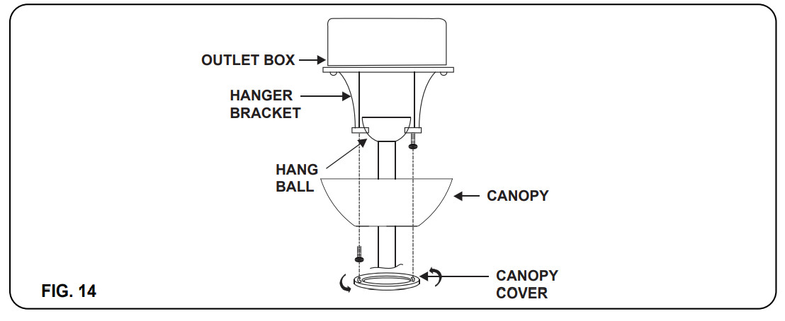
Step 1. Remove 1 of the 2 screws from the bottom of the hanger bracket and loosen the other half a turn from the screw head. (Fig.14)Step 2. Slide the canopy up towards the hanger bracket and place the keyhole on the canopy over the screw on the hanger bracket, turn the canopy until it locks in place at the narrow section of the keyhole.Step 3. Align the circular hole on the canopy with the remaining hole on the hanger bracket, secure by tightening the two set screws. Note: Adjust the canopy screws as necessary until the canopy and canopy cover is snug.
INSTALLING THE BLADE TO THE FLYWHEEL
Insert the blade through the slot on the flywheel. Starting from the center hole, fasten the blade to the flywheel by using the blade screw and fiber washer(Fig.15-a). Align the blade holder to the blade (as shown In FIg.15-b) and secure using two blade screws and two fiber washers. Repeat this step for the other four blades.

INSTALLING THE 16W LED ASSEMBLY
CAUTION: To Reduce The Risk 01 Electric Shock, Disconnect The Electrical Supply Circuit To The Fan Before Installing The Light Kit.Step 1. While holding the 16W LED assembly under your fan, firmly snap the wire connection plugs together.Step 2. Attach the 16W LED assembly to the switch box by twisting tightly.NOTE: This is an integrated LED light kit assembly and can not be disassembled to prevent electronic shock.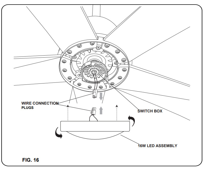
OPERATING THE REMOTE CONTROL
Remote Control only: Install an A23 12-volt battery (included). (Fig. 17) To prevent damage to the transmitter remove The battery if not used for long periods of time.Restore Power to Ceiling Fan.
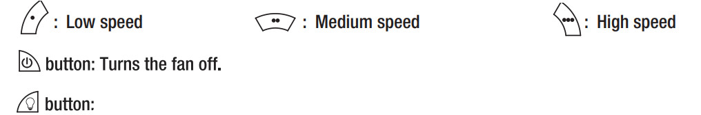 Turns the light on or off and also controls the brightness setting. Press and release this button to turn the light on or off. Press and hold the button to set the desired brightness. The light button has an auto-resume, it will stay at the same brightness as the last time it was turned off.

Speed settings for summer or winter weather depend on factors such as room size, ceiling height and the number of fans. The reverse switch Is located under the coupling cover (Figure 20). Slide the switch to left for warm weather operation. Slide the switch to the right for cool weather operation.NOTE: Wait for fan to stop before changing the setting of the slide switch.Summer Weather (counter-clockwise blade rotation) A DOWNWARD airflow creates a cooling effect as shown in Figure 22. This allows you to set your air conditioner in a warmer setting without affecting your comfort.Winter Weather (Clockwise blade rotation) An UPWARD airflow moves warmer air off the ceiling area as shown in Figure 21. This allows you to set your heating unit on a cooler setting without affecting your comfort.

CARE OF YOUR FAN
Here are some suggestions to help maintain your fan.
- Because of the fan’s natural movement, some connections may become loose. Check the support connections, brackets and blade attachments twice a year. Make sure they are secure. (It is not necessary to remove fan from the ceiling).
- Clean your fan periodically to help maintain its new appearance over the year.CAUTION: many common household cleaning products contain chemicals that could damage the finish of your fan. Use only a soft lint-free cloth and soapy water.
- ft your fan is provided with wood veneer blades; you can apply a light coat of furniture polish for additional protection and enhanced beauty. Cover small scratches with a light application of shoe polish.
- Use a lint-free lightly damp cloth or duster to remove dust from the blades.
- There is no need to oil your fan. The motor has permanently lubricated bearings.
- If your fan is provided with glass shades, clean with lukewarm soapy water and a soft cloth or sponge. DO NOT IMMERSE GLASS SHADES IN HOT WATER. DO NOT PUT GLASS SHADES INTO AN AUTOMATIC DISHWASHER.
WARNING! MAKE SURE THE POWER IS OFF AT THE ELECTRICAL PANEL BOX BEFORE YOU ATTEMPT ANY REPAIRS. REFER TO THE SECTION, “ELECTRICAL CONNECTIONS”.
TROUBLESHOOTING
| SYMPTOM | SOLUTION |
| Fan will not start | • Check to make sure the wall switch is turned on.• Check circuit fuses or breakers.• Caution! Make sure the power is turned off before performing the following steps.• Remove canopy and check wire connections.• Check wall control transmitter connections (if applicable).• Note: Fan must be installed at a maximum distance of 40 feet from the transmitting unit for proper signal transmission between the transmitting unit and the fan’s receiving unit. |
| Fan Sounds Noisy | • Allow a 24-hour “break-in” period. Most noises associated with a new fan will go away during this time.• Make sure the screws that attach the fan blade holder to the motor hub is tight. • Make sure outlet box is secured to building structure, if necessary use the wood screws provided to further secure outlet box to joist.• Make sure hanger bracket is secure to the outlet box, screws are tight |
| Fan Wobble | • NOTE: All blade sets are grouped by weight Because wood and plastic blades vary in density, the fan may wobble even though blades are matched.• Make sure outlet box is secured to building structure, if necessary use the wood screws provided to further secure outlet box to joist.• Make sure hanger bracket is secure to the outlet box, screws are tight• If a Balancing kit is provided follow the instructions included with the balancing kit to help correct any excessive wobble. |
| The remote control is not working. | • Do not connect the fan with wall-mounted variable speed control(s).• Check to make sure the dip switches from the remote control and receiver are set to the same frequency |
SPECIFICATIONS
| Fan Size | Speed | Volts | Amps | Watts | RPM | CFM | N.W. | G.W. | C.F. |
| 52″ | Low | 120 | 0.25 | 16. | 74 | 2072 | 7.1 kgs | 8.11kgs | 1.435′ |
| High | 120 | 0.48 | 57. | 160 | 4789 |
These are typical readings. Your actual fan may vary. They do not include amps and wattage used by the light(s).
Supplier’s Declaration of Conformity47 CFR§2.1077 compliance InformationUnique IdentifierTrade name: MINKA CEILING FAN CO.Model Number: XXXXXResponsible Party-U.S Contact InformationMinka Group Inc.1151 West Bradford Court.Corona, CA 92882 Tel. 951-735-9220FCC Compliance Statement: products subject to Part 15This device complies with Part 15 of the FCC rules. Operation is subject to the following two conditions: (1) This device may not cause harmful interference, and (2) This device must accept any interference received, including interference that may cause undesired operation.Warning: Changes or modifications to this unit not expressly approved by the party responsible for compliance could void the user’s authority to operate the equipment.Note: This equipment has been tested and found to comply with the limits for a Class B digital device, pursuant to part 15 of the FCC rules. These limits are designed to provide reasonable protection against harmful interference in a residential installation. This equipment generates, uses, and can radiate radio frequency energy and, if not installed and used in accordance with the instructions, may cause harmful interference to radio communications. However, there is no guarantee that interference will not occur in a particular installation. If this equipment does cause harmful interference to radio or television reception, which can be determined by turning the equipment off and on, the user is encouraged to try and correct the interference by one or more of the following measures: Reorient or relocate the receiving antenna. Increase the separation between the equipment and receiver. Connect the equipment into an outlet on a circuit different from that to which the receiver is connected. Consult the dealer or an experienced radio/TV technician for help.
For any additional information about your Minka Ceiling fan, please write to:![]() 1151 W. Bradford Court, Corona, CA 92882 • For Customer Assistance Call: 1-800-307-3267
1151 W. Bradford Court, Corona, CA 92882 • For Customer Assistance Call: 1-800-307-3267
References
[xyz-ips snippet=”download-snippet”]