
![]()
![]()
ENDURA C2
TRANSOM-MOUNT TROLLING MOTORUSER MANUAL
CE MASTER USER MANUAL (FOR CE CERTIFIED MODELS)
THANK YOU
Thank you for choosing Minn Kota. We believe that you should spend more time fishing and less time positioning your boat.That’s why we build the smartest, toughest, most intuitive trolling motors on the water. Every aspect of a Minn Kota trolling motor is thought out and rethought until it’s good enough to bear our name. Countless hours of research and testing provide you the Minn Kota advantage that can truly take you “Anywhere. Anytime.” We don’t believe in shortcuts. We are Minn Kota. And we are never done helping you catch more fish.
REMEMBER TO KEEP YOUR RECEIPT AND IMMEDIATELY REGISTER YOUR TROLLING MOTOR.
NOTE: Do not return your Minn Kota motor to your retailer. Your retailer is not authorized to repair or replace this unit. You may obtain service by: calling Minn Kota; returning your motor to the Minn Kota Factory Service Center; sending or taking your motor to any Minn Kota authorized service center. A list of authorized service centers is available on our website. Please include proof of purchase, serial number and purchase date for warranty service with any of the above options.
Please thoroughly read this user manual. Follow all instructions and heed all safety and cautionary notices below. Use of this motor is only permitted for persons that have read and understood these user instructions. Minors may use this motor only under adult supervision.
ATTENTION: Never run the motor out of the water, as this may result in injuries from the rotating propeller. The motor should be disconnected from the power source when it is not in use or is off the water. When connecting the power-supply cables of the motor to the battery, ensure that they are not kinked or subject to chafe and route them in such a way that persons cannot trip over them. Before using the motor make sure that the insulation of the power cables is not damaged. Disregarding these safety precautions may result in electric shorts of battery(s) and/or motor. Always disconnect motor from battery(s) before cleaning or checking the propeller. Avoid submerging the complete motor as water may enter the lower unit through control head and shaft. If the motor is used while water is present in the lower unit considerable damage to the motor can occur. This damage will not be covered by warranty.
CAUTION: Take care that neither you nor other persons approach the turning propeller too closely, neither with body parts nor with objects. The motor is powerful and may endanger or injure you or others. While the motor is running watch out for persons swimming and for floating objects. Persons whose ability to run the motor or whose reactions are impaired by alcohol, drugs, medication, or other substances are not permitted to use this motor. This motor is not suitable for use in strong currents. The constant noise pressure level of the motor during use is less than 70dB(A). The overall vibration level does not exceed 2,5m/sec2.
LOCATING YOUR SERIAL NUMBER
Your Minn Kota 11-character serial number is very important. It helps to determine the specific model and year of manufacture. When contacting Consumer Service or registering your product, you will need to know your product’s serial number. We recommend that you write the serial number down in the space provided below so that you have it available for future reference.
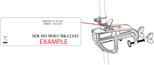
The serial number on your Endura C2 is located on the top of the transom bracket.
TWO-YEAR LIMITED WARRANTY
WARRANTY ON MINN KOTA FRESHWATER TROLLING MOTORS
Johnson Outdoors Marine Electronics, Inc. (“JOME”) extends the following limited warranty to the original retail purchaser only. Warranty coverage is not transferable.
MINN KOTA LIMITED TWO-YEAR WARRANTY ON THE ENTIRE PRODUCT
JOME warrants to the original retail purchaser only that the purchaser’s new Minn Kota freshwater trolling motor will be materially free from defects in materials and workmanship appearing within two (2) years after the date of purchase. JOME will (at its option) either repair or replace, free of charge, any parts found by JOME to be defective during the term of this warranty. Such repair, or replacement shall be the sole and exclusive liability of JOME and the sole and exclusive remedy of the purchaser for breach of this warranty.
MINN KOTA LIMITED LIFETIME WARRANTY ON COMPOSITE SHAFT
JOME warrants to the original retail purchaser only that the composite shaft of the purchaser’s Minn Kota trolling motor will be materially free from defects in materials and workmanship appearing within the original purchaser’s lifetime. JOME will provide a new composite shaft, free of charge, to replace any composite shaft found by JOME to be defective during the term of this warranty. Providing a new composite shaft shall be the sole and exclusive liability of JOME and the sole and exclusive remedy of the purchaser for breach of this warranty; and purchaser shall be responsible for installing, or for the cost of labor to install, any new composite shaft provided by JOME.
EXCLUSIONS & LIMITATIONS
This limited warranty does not apply to products that have been used in saltwater or brackish water, commercially or for rental purposes. This limited warranty does not cover normal wear and tear, blemishes that do not affect the operation of the product, or damage caused by accidents, abuse, alteration, modification, shipping damages, acts of God, negligence of the user or misuse, improper or insufficient care or maintenance. DAMAGE CAUSED BY THE USE OF OTHER REPLACEMENT PARTS NOT MEETING THE DESIGN SPECIFICATIONS OF THE ORIGINAL PARTS WILL NOT BE COVERED BY THIS LIMITED WARRANTY. The cost of normal maintenance or replacement parts which are not in breach of the limited warranty are the responsibility of the purchaser. Prior to using products, the purchaser shall determine the suitability of the products for the intended use and assumes all related risk and liability. Any assistance JOME provides to or procures for the purchaser outside the terms, limitations or exclusions of this limited warranty will not constitute a waiver of the terms, limitations or exclusions, nor will such assistance extend or revive the warranty. JOME will not reimburse the purchaser for any expenses incurred by the purchaser in repairing, correcting or replacing any defective products or parts, except those incurred with JOME’s prior written permission.JOME’S AGGREGATE LIABILITY WITH RESPECT TO COVERED PRODUCTS IS LIMITED TO AN AMOUNT EQUAL TO THE PURCHASER’S ORIGINAL PURCHASE PRICE PAID FOR SUCH PRODUCT.
MINN KOTA SERVICE INFORMATION
To obtain warranty service in the U.S., the product believed to be defective, and proof of original purchase (including the date of purchase), must be presented to a Minn Kota Authorized Service Center or to Minn Kota’s factory service center in Mankato, MN. Any charges incurred for service calls, transportation or shipping/freight to/from the Minn Kota Authorized Service Center or factory, labor to haul out, remove, re-install or re-rig products removed for warranty service, or any other similar items are the sole and exclusive responsibility of the purchaser. Products purchased outside of the U.S. must be returned prepaid with proof of purchase (including the date of purchase and serial number) to any Authorized Minn Kota Service Center in the country of purchase. Warranty service can be arranged by contacting a Minn Kota Authorized Service Center or by contacting the factory. Products repaired or replaced will be warranted for the remainder of the original warranty period [or for 90 days from the date of repair or replacement, whichever is longer]. For any product that is returned for warranty service that JOME finds to be not covered by or not in breach of this limited warranty, there will be a billing for services rendered at the prevailing posted labor rate and for a minimum of at least one hour.
NOTE: Do not return your Minn Kota product to your retailer. Your retailer is not authorized to repair or replace products.
THERE ARE NO EXPRESS WARRANTIES OTHER THAN THESE LIMITED WARRANTIES. IN NO EVENT SHALL ANY IMPLIED WARRANTIES INCLUDING ANY IMPLIED WARRANTIES OF MERCHANTABILITY OR FITNESS FOR PARTICULAR PURPOSE, EXTEND BEYOND THE DURATION OF THE RELEVANT EXPRESS LIMITED WARRANTY. IN NO EVENT SHALL JOME BE LIABLE FOR PUNITIVE, INDIRECT, INCIDENTAL, CONSEQUENTIAL OR SPECIAL DAMAGES. Without limiting the foregoing, JOME assumes no responsibility for loss of use of product, loss of time, inconvenience or other damage.
Some states do not allow limitations on how long an implied warranty lasts or the exclusion or limitation of incidental or consequential damages, so the above limitations and/or exclusions may not apply to you. This warranty gives you specific legal rights and you may also have other legal rights which vary from state to state.
FEATURES
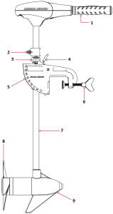
- Telescoping Handle Controls: On/Off, Speed, Forward/Reverse and Direction
- Adjustable Depth Collar
- Steering Tension Knob
- Quick Release Tilt Lever
- 10-Position Lever Lock Mounting Bracket
- Transom Clamp Screws
- Lifetime Warranty Flexible Composite Shaft
- Power Prop*
- Cool Quiet Power Motor
Specifications subject to change without notice.*This diagram is for reference only and may differ from your actual motor.
INSTALLATION
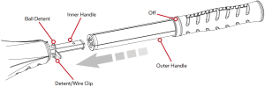
HANDLE INSTALLATION
- Remove the wire clip from the ball detent located on the inner handle.
- Install outer handle over inner handle. Position the handles so the ball detent and OFF are aligned.
- Push the outer handle into the control box until handle “clicks” into place. The handle is held in place with locking fingers, so some force may be required to lock the handles together.
- Once the handle is locked into the control box, it can be rotated and extended for normal use.
- Once the handle is installed, the assembly is permanent. Do not attempt to remove the handle.
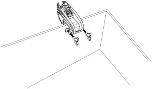
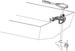
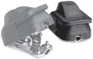
MOTOR INSTALLATION
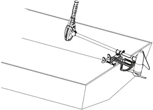
- Find a transom area of the boat that is free from obstructions.
- Open the clamp screws on the bracket enough so that it will fit over the top of the boat transom.
- Place the Lever Lock Mounting bracket over the top of the boat transom so that the bracket is resting on top of the transom.
- Verify that there are no obstacles that the control box, handle, or prop might hit while in use that would restrict steering or cause damage to the motor.
- Tighten down the clamp screws to the transom by hand only. Do not use any tools to tighten the clamp screws as this may damage the bracket or your boat.
- We recommend the tilt angle of the motor to be adjusted so that the motor shaft is perpendicular to the water surface when the motor is in use.
- For transport, always tilt the motor into the boat, such that the motor and prop assembly are completely out of the water and the motor is positioned up close to the lever lock bracket.
NOTE: When setting the depth, be sure the top of the motor is submerged at least 12” to avoid churning or agitation of surface water. The propeller must be completely submerged.
CAUTION:• Never operate your motor when it is out of the water.• Over-tightening the clamp screws can damage the bracket.
BATTERY WIRING & INSTALLATION
BOAT RIGGING & PRODUCT INSTALLATION
For safety and compliance reasons, we recommend that you follow American Boat and Yacht Council (ABYC) standards when rigging your boat. Altering boat wiring should be completed by a qualified marine technician. The following specifications are for general guidelines only:CAUTION: These guidelines apply to general rigging to support your Minn Kota motor. Powering multiple motors or additional electrical devices from the same power circuit may impact the recommended conductor gauge and circuit breaker size. If you are using wire longer than that provided with your unit, follow the conductor gauge and circuit breaker sizing table below. If your wire extension length is more than 25 feet, we recommend that you contact a qualified marine technician.An over-current protection device (circuit breaker or fuse) must be used. Coast Guard requirements dictate that each ungrounded current-carrying conductor must be protected by a manually reset, trip-free circuit breaker or fuse. The type (voltage and current rating) of the fuse or circuit breaker must be sized accordingly to the trolling motor used. The table below gives recommended guidelines for circuit breaker sizing.
Reference:United States Code of Federal Regulations: 33 CFR 183 – Boats and Associated EquipmentABYC E-11: AC and DC Electrical Systems on Boats
CONDUCTOR GAUGE AND CIRCUIT BREAKER SIZING TABLE
| Motor Thrust / Model | Max Amp Draw | Circuit Breaker | Wire Extension Length * | ||||
| 5 feet | 10 feet | 15 feet | 20 feet | 25 feet | |||
| 30 lb. | 30 | 50 Amp @ 12 VDC | 10 AWG | 10 AWG | 8 AWG | 6 AWG | 4 AWG |
| 40 lb., 45 lb. | 42 | 10 AWG | 8 AWG | 6 AWG | 4 AWG | 4 AWG | |
| 50 lb., 55 lb. | 50 | 60 Amp @ 12 VDC | 8 AWG | 6 AWG | 4 AWG | 4 AWG | 2 AWG |
| 70 lb. | 42 | 50 Amp @ 24 VDC | 10 AWG | 10 AWG | 8 AWG | 8 AWG | 6 AWG |
| 80 lb. | 56 | 60 Amp @ 24 VDC | 8 AWG | 8 AWG | 8 AWG | 6 AWG | 6 AWG |
| 101 lb. | 46 | 50 Amp @ 36 VDC | 8 AWG | 8 AWG | 8 AWG | 8 AWG | 8 AWG |
| Engine Mount 101 | 50 | 60 Amp @ 36 VDC | 8 AWG | 6 AWG | 4 AWG | 4 AWG | 2 AWG |
| 112 lb. | 52 | 60 Amp @ 36 VDC | 8 AWG | 8 AWG | 8 AWG | 8 AWG | 8 AWG |
| Engine Mount 160 | 116 | (2) x 60 Amp @ 24 VDC | 2 AWG | 2 AWG | 2 AWG | 2 AWG | 2 AWG |
| E-Drive | 40 | 50 Amp @ 48 VDC | 10 AWG | 10 AWG | 10 AWG | 10 AWG | 10 AWG |
This conductor and circuit breaker sizing table is only valid for the following assumptions:
- No more than 3 conductors are bundled together inside of a sheath or conduit outside of engine spaces.
- Each conductor has 105° C temp rated insulation.
- No more than 5% voltage drop allowed at full motor power based on published product power requirements.
*Wire Extension Length refers to the distance from the batteries to the trolling motor leads.
SELECTING THE CORRECT BATTERIES
The motor will operate with any lead acid, deep cycle marine 12 volt battery/batteries. For best results, use a deep cycle, marine battery with at least a 105 ampere hour rating. Maintain battery at full charge. Proper care will ensure having battery power when you need it, and will significantly improve the battery life. Failure to recharge lead-acid batteries (within 12-24 hours) is the leading cause of premature battery failure. Use a multi-stage charger to avoid overcharging. We off er a wide selection of chargers to fi t your charging needs. If you are using a crank battery to start a gasoline outboard, we recommend that you use a separate deep cycle marine battery/batteries for your Minn Kota trolling motor.
Advice Regarding Batteries:
- Never connect the (+) and the (–) terminals of the same battery together. Take care that no metal object can fall onto the battery and short the terminals. This would immediately lead to a short and extreme fire danger.
- It is highly recommended that a circuit breaker or fuse be used with this trolling motor. Refer to “Conductor Gauge and Circuit Breaker Sizing Table” in the previous section to find the appropriate circuit breaker or fuse for your motor. For motors requiring a 60-amp breaker, the Minn Kota MKR-19 60-amp circuit breaker is recommended.
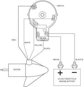
CONNECTING THE BATTERIES
12 VOLT SYSTEMS:
- Make sure that the motor is switched off (speed selector on “OFF” or “0”).
- Connect positive ( + ) red lead to positive ( + ) battery terminal.
- Connect negative ( – ) black lead to negative ( – ) battery terminal.
- For safety reasons do not switch the motor on until the propeller is in the water.
CAUTION:For safety reasons, disconnect the motor from the battery/batteries when the motor is not in use or while the battery/batteries are being charged.
MOTOR WIRING DIAGRAM
USING & ADJUSTING THE MOTOR
ADJUSTING THE DEPTH OF THE MOTOR
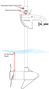
When setting the depth be sure the top of the motor is submerged at least 12” to avoid churning or agitation of surface water. The propeller must be completely submerged.
- Firmly grasp the composite shaft and hold it steady.
- Loosen the steering tension knob and adjustable depth collar knob until the shaft slides freely.
- Raise or lower the motor to the desired depth.
- Tighten adjustable depth collar knob to secure the motor in place.
CAUTION:
- Never operate your motor when it is out of the water.
- Over-tightening the clamp screws can damage the bracket.
- Never loosen the steering tension knob without securely holding the shaft of the motor. Failing to do so will cause the motor to rapidly fall against the bracket.
ADJUSTING THE STEERING
- Adjust the steering tension knob to provide enough tension to allow the motor to turn freely, yet remain in any position without being held
OR
- Tighten the knob to place the motor in a preset position to leave your hands free for fishing.
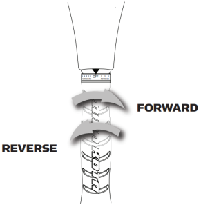
CONTROLLING SPEED AND DIRECTION WITH THE TILLER
These motors are equipped with an extension twist tiller with a telescoping handle, which offers a choice of five forward and three reverse speeds. The speed control may be operated in either direction, forward or reverse. Turn the tiller handle counterclockwise from (OFF) to increase reverse speed and clockwise from (OFF) to increase forward speed. Thrust decreases as you approach (OFF) from either direction.
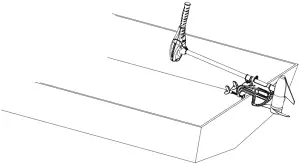
ADJUSTING THE BRACKET
You can lock your motor in a vertical position, angle it for shallow water or tilt it completely out of the water.
- Firmly grasp the control head or composite shaft.
- Press the tilt lever toward the shaft and hold to release the detent lock or T-bar to adjust the position of the mounting bracket.
- Tilt to any of the positions on the mounting bracket.
- Release the tilt lever.
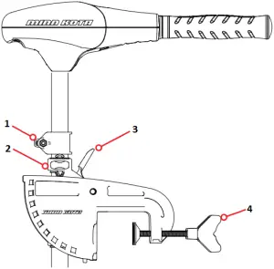
- Depth Adjustment Knob
- Steering Tension Knob
- Quick Release Tilt Lever
- Clamp Screws
STOWING THE MOTOR
- Adjust depth so that the motor is fully raised.
- Press and hold tilt lever.
- Tilt motor into the boat.
- For transport, always tilt the motor into the boat such that the motor and prop assembly are completely out of the water and the motor is positioned up close to the lever lock bracket.
WARNING: When raising/lowering motor or operating the tilt mechanism, keep fingers clear of all hinge and pivot points and all moving parts.
SERVICE & MAINTENANCE
PROPELLER REPLACEMENT
TOOLS AND RESOURCES REQUIRED:
- Box End Wrench– 1/2” for motors with 70 lbs thrust or lower.– 9/16” for motors with 80 lbs thrust or higher.
- Screwdriver (optional)
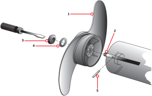
- Propeller
- Slot End
- Prop Nut
- Washer
- Drive Pin
CAUTION:Disconnect the motor from the battery before beginning any prop work or maintenance.NOTE: The propeller on your motor may differ from the one pictured.
- Disconnect the motor from all sources of power prior to changing the propeller.
- Hold the propeller and loosen the prop nut with pliers or a wrench.
- Remove the prop nut and washer. If the drive pin is sheared or broken, you will need to hold the shaft stationary with a blade screwdriver pressed into the slot on the end of the shaft.
- Turn the old prop to horizontal (as illustrated) and pull it straight off . If drive pin falls out, push it back in.
- Align the new propeller with the drive pin.
- Install the prop washer and prop nut.
- Tighten the prop nut 1/4 turn past snug [25-35 inch lbs.] Do not over tighten as this can damage the prop.
GENERAL MAINTENANCE
- After use, the entire motor should be rinsed with freshwater. This series of motors is not equipped for saltwater exposure.
- The composite shaft requires periodic cleaning and lubrication for proper retraction and deployment. A coating of an aqueous based silicone spray will improve operation.
- The propeller must be inspected and cleaned from weeds and fishing line after every use.Fishing line and weeds can get behind the prop, damage the seals and allow water to enter the motor.
- Verify the prop nut is secure each time the motor is used.
- To prevent accidental damage during transportation or storage, disconnect the battery whenever the motor is off of the water.For prolonged storage, lightly coat all metal parts with an aqueous based silicone spray.
- For maximum battery life recharge the battery(s) as soon as possible after use. For maximum motor performance restore battery to full charge prior to use.
- Keep battery terminals clean with fine sandpaper or emery cloth.
- The propeller is designed to provide weed free operation with very high efficiency. To maintain this top performance, the leading edge of the blades must be kept smooth. If they are rough or nicked from use, restore to smooth by sanding with fine sandpaper.
TROUBLESHOOTING & REPAIR
- Motor fails to run or lacks power:• Check battery connections for proper polarity.• Make sure terminals are clean and corrosion free. Use fine sandpaper or emery cloth to clean terminals.• Check battery water level. Add water if needed.
- Motor loses power after a short running time:• Check battery charge. If low, restore to full charge.
- Motor is difficult to steer:• Loosen the steering tension knob on the bracket• Lubricate the composite shaft.
- You experience prop vibration during normal operation:• Remove and rotate the prop 180°. See removal instructions in the Propeller Replacement section.
- Experiencing interference with your fishfinder:• You may, in some applications, experience interference in your depth finder display. We recommend that you use a seperate deep cycle marine battery for your trolling motor and that you power the depth finder from the starting/cranking battery.
PARTS DIAGRAM
ENDURA C2 30
30 LBS THRUST – 12 VOLT – 30” SHAFT
This page provides Minn Kota® WEEE compliance disassembly instructions. For more information about where you should dispose of your waste equipment for recycling and recovery and/or your European Union member state requirements, please contact your dealer or distributor from which your product was purchased.Tools required, but not limited to: fl at head screw driver, Phillips screw driver, socket set, pliers, wire cutters.

PARTS LIST
ENDURA C2 3030 LBS THRUST – 12 VOLT – 30” SHAFT
| ITEM | QTY | PART NUMBER | DESCRIPTION |
| 1 | 1 | 2-100-287 | ARMATURE ASSEMBLY 12V 3.25 |
| 2 | 1 | 788-015 | RETAINING RING |
| 3 | 1 | 2-200-188 | HOUSING ASSEMBLY CENTER 3.25 TXT |
| 4 | 1 | 2-300-142 | BRUSH END HOUSING ASSEMBLY 3.25 SP.CO |
| 5 | 1 | 2-400-128 | PLAIN END HOUSING ASSEMBLY 3.25 |
| 6 | 1 | 880-003 | SEAL |
| 7 | 1 | 880-006 | SEAL W/SHIELD |
| 8 | 1 | 140-010 | BALL BEARING |
| 9 | 2 | 188-052 | BRUSH ASSEMBLY |
| 11 | 1 | 738-030 | BRUSH PLATE W/HOLDER 3.25 |
| 14 | 2 | 975-032 | COMPRESSION SPRING |
| 17 | 2 | 701-007 | O-RING — THRU BOLT |
| 18 | 1 | 701-039 | O-RING |
| 19 | 1 | 701-041 | O-RING |
| 20 | 2 | 830-001 | SCREW — SELF THREAD #8-32X1.7 |
| 21 | 2 | 830-062 | THRU BOLT #8-32X8.0 |
| 22 | 1 | 990-067 | WASHER — STEEL THRUST |
| 23 | 2 | 990-070 | WASHER — NYLATRON |
| 24 | 1 | 144-049 | FLANGE BEARING (SERVICE ONLY) |
| 25 | 1 | 2069278 | MOTOR ASSEMBLY 12 V 3.25 5SP |
| 26 | 1 | 2032045 | 30” COMPOSITE TUBE |
| ▪ | 1 | 1378121 | PROPELLER KIT (INCLUDES 28-31) |
| 28 | 1 | 2061122 | PROPELLER 3.25 HUB DIA |
| 29 | 1 | 2151726 | WASHER — 5/16 STD SS |
| 30 | 1 | 2053101 | NUT — PROP NYLOCK (MED) SS |
| 31 | 1 | 2092600 | DRIVE PIN |
| ▪ | 1 | 2771818 | BRACKET & HINGE ASSEMBLY (INCLUDES 32-43) |
| ▪ | 1 | 2771910 | BRACKET ASSEMBLY (INCLUDES 32, 34, 35) |
| *32 | 1 | 2061910 | BRACKET |
| 33 | 1 | 2060510 | HINGE PIN |
| *34 | 2 | 2061300 | SCREW — CLAMP |
| *35 | 2 | 2011710 | WASHER — CLAMP SCREW |
| 36 | 1 | 2063605 | PLASTIC T-BAR |
| 37 | 1 | 2062706 | T-BAR SPRING |
| 38 | 1 | 2067201 | BLACK TILT LEVER |
| 39 | 1 | 2061810 | PLASTIC HINGE |
| 40 | 2 | 2037301 | HINGE BUSHING |
| 41 | 1 | 2062800 | SNAP-IN TENSION BLOCK |
| 42 | 1 | 2011385 | SCREW — TENSION/KNOB |
| 43 | 1 | 2060515 | TILT LEVER PIN |
| 44 | 1 | 2061520 | DEPTH COLLAR |
| 45 | 1 | 2011365 | SCREW — COLLAR/NEW KNOB |
| 46 | 1 | 2020606 | LEADWIRE (14 GA) W/SPADE TERM |
| 47 | 2 | 2020703 | SPADE TERMINAL 14GA HD |
| 48 | 1 | 2256300 | TIE WRAP |
| 49 | 1 | 2062515 | CONTROL BOX |
| 50 | 1 | 2060215 | CONTROL BOX COVER |
| 51 | 1 | 2065700 | DECAL COVER ENDURA C2 30 |
| 52 | 1 | 2064023 | SWITCH — FWD/REV 5 SP |
| 53 | 1 | 2033401 | SCREW — #10-24 X 1-3/4 |
| 54 | 1 | 2013110 | NUT — 10-24 HEX |
| 55 | 6 | 2012100 | SCREW — #8-18 X 5/8 |
| 56 | 1 | 2990919 | INNER HANDLE ASSEMBLY |
| 57 | 1 | 2060405 | HANDLE PIVOT |
| 58 | 1 | 2012104 | SCREW — #6 X 1/2” SS |
| 59 | 1 | 2990928 | OUTER HANDLE ASSEMBLY |
| 60 | 1 | 2060009 | FRONT BEARING |
| ▪ | 1 | 2883460 | SEAL AND O-RING KIT |
▪ THIS ITEM IS PART OF AN ASSEMBLY.* THIS ITEM IS PART OF A KIT AND ONLY LISTED FOR VIEWING PURPOSES.
COMPLIANCE STATEMENTS
ENVIRONMENTAL COMPLIANCE STATEMENT:
It is the intention of JOME to be a responsible corporate citizen, operating in compliance with known and applicable environmental regulations, and a good neighbor in the communities where we make or sell our products.
WEEE DIRECTIVE:
EU Directive 2002/96/EC “Waste of Electrical and Electronic Equipment Directive (WEEE)” impacts most distributors, sellers, and manufacturers of consumer electronics in the European Union. The WEEE Directive requires the producer of consumer electronics to take responsibility for the management of waste from their products to achieve environmentally responsible disposal during the product life cycle.
 WEEE compliance may not be required in your location for electrical & electronic equipment (EEE), nor may it be required for EEE designed and intended as fixed or temporary installation in transportation vehicles such as automobiles, aircraft, and boats. In some European Union member states, these vehicles are considered outside of the scope of the Directive, and EEE for those applications can be considered excluded from the WEEE Directive requirement.
This symbol (WEEE wheelie bin) on product indicates the product must not be disposed of with other household refuse. It must be disposed of and collected for recycling and recovery of waste EEE. Johnson Outdoors Inc. will mark all EEE products in accordance with the WEEE Directive. It is our goal to comply in the collection, treatment, recovery, and environmentally sound disposal of those products; however, these requirement do vary within European Union member states. For more information about where you should dispose of your waste equipment for recycling and recovery and/or your European Union member state requirements, please contact your dealer or distributor from which your product was purchased.
DISPOSAL:
Minn Kota motors are not subject to the disposal regulations EAG-VO (electric devices directive) that implements the WEEE directive. Nevertheless never dispose of your Minn Kota motor in a garbage bin but at the proper place of collection of your local town council.
Never dispose of battery in a garbage bin. Comply with the disposal directions of the manufacturer or his representative and dispose of them at the proper place of collection of your local town council.
WARNING: This product contains chemicals known to the State of California to cause cancer and birth defects or other reproductive harm.
RECOMMENDED ACCESSORIES
ON-BOARD & PORTABLE BATTERY CHARGERS
Stop buying new batteries and start taking care of the ones you’ve got. Many chargers can actually damage your battery over time – creating shorter run times and shorter overall life. Digitally controlled Minn Kota chargers are designed to provide the fastest charge that protect and extend battery life.
 MK345PC
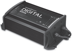 MK210D
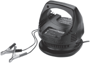 MK110P
TALON SHALLOW WATER ANCHOR
Talon deploys faster, holds stronger and runs quieter than any other shallow water anchor. Available in depths up to 12’ and bold color options including camo, it boasts an arsenal of features and innovations that no other anchor can touch:

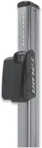
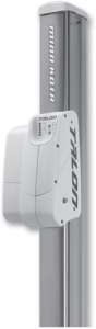
- Vertical, Multi-Stage Deployment
- User-Selectable Anchoring Modes
- 2x Anchoring Force
- Fast Deploy
- Auto Up/Down
- Triple Debris Shields
- Built-In Wave Absorption
- Noise Dissipation
- Versatile Adjustments
MINN KOTA ACCESSORIES
We offer a wide variety of trolling motor accessories, including:

 report this ad
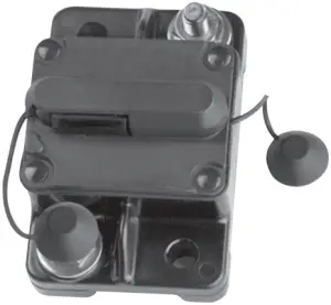
- 60-Amp Circuit Breaker
- Mounting Brackets
- Stabilizer Kits
- Extension Handles
- Battery Connectors
- Battery Boxes
- Quick Connect Plugs
Check out the collection of boat parts & hardware we offer.
[xyz-ips snippet=”download-snippet”]