
MINN KOTA 1810253 Wireless Stomp Switch Quick Reference Guide
Compatible with Raptor and Bluetooth® enabled Talon Systems only.
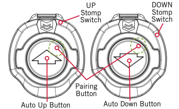
STOMP SWITCH
![]()
Auto Up Button/ Pairing Button
Single press to AUTO retract the anchor. For the Raptor anchor, press and hold to continually retract. The Raptor will continue to retract when the button is held until the button is released. Top right used to pair the Wireless Stomp Switch to a Talon or Raptor.
![]()
Auto Down Button/ Pairing Button
Double press to AUTO deploy the anchor. For the Raptor anchor, single press and hold to continually deploy. The Raptor will continue to deploy when the button is held until it reaches its full range of operation or until the button is released. Top right used to pair the Wireless Stomp Switch to a Talon or Raptor.
INSTALLING THE WIRELESS STOMP SWITCH
Your new Wireless Stomp Switch comes complete with all of the hardware you’ll need to install it directly to the deck of your boat. Please review the parts list, mounting considerations and tools needed for installation prior to getting started.
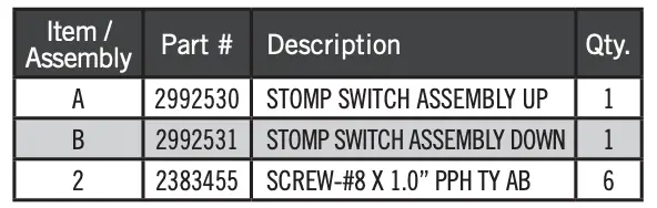
Installation Parts List
Mounting Considerations
Before mounting your Wireless Stomp Switch, please give consideration to the following:
a. Examine your boat to ensure that you will not drill into any obstructions and that the hardware will be accessible for assembly.
b. Make sure the area under the mounting location is flat, clear to drill holes and that the installation hardware will not damage existing components below the mounting surface. It may be necessary to shim or modify the mounting surface under the mounting location to create a flat area for the Wireless Stomp Switch Pedestal to be mounted.
c. Mount the Wireless Stomp Switch in an area that has a clear line of communication with the Talon(s)/Raptor(s) it is intended to control for optimum performance.
d. Mount the Wireless Stomp Switch in an area where it will not become a tripping hazard.
NOTICE: Raptor and Bluetooth® Talon require the latest available software before use.
Tools and Resources Required
- Pencil or similar marking tool
- Drill
- #2 Phillips Driving Bit
Installation
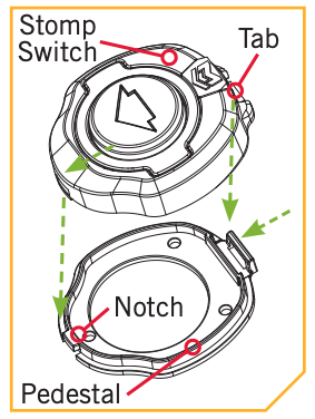
a. Review the Mounting Considerations to determine an acceptable mounting location. Once a location is selected, take the Wireless Stomp Switch Assembly (Assembly #A or B) and remove the Pedestal from the Base by squeezing the Tab on the top side of the Stomp Switch by the molded logo and pulling the Stomp Switch and Pedestal apart.
NOTICE: The Pedestal comes attached to the Wireless Stomp Switch and needs to be removed for installation.
NOTICE: This installation process should be repeated for both Wireless Stomp Switch Assemblies (Assembly #A and B).
b. The Pedestal has three Mounting Holes that are used to secure it to the boat. The bottom side of the Pedestal is smooth. The smooth side should be placed down, towards the boat when the Pedestal is installed. Position the Pedestal at the selected location and mark the Mounting Holes with a pencil or similar marking tool.

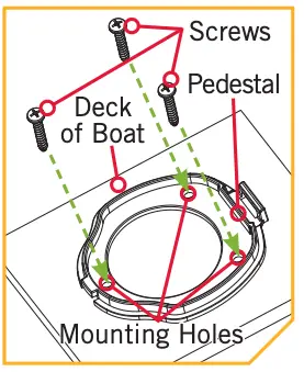 c. Double check the Mounting Location. Take the Screws (Item #2) and place one each in the Mounting Holes of the Pedestal. Make sure the Mounting Holes line up with the Marked Locations and then use a Drill with #2 Phillips Driving Bit to secure the Pedestal to the Deck of the Boat. Do not over-tighten.
d. Once the Pedestal is installed, take the Wireless Stomp Switch and reattach it to the Pedestal. Make sure the Notch on the Pedestal is aligned and then click the Tab in place so that the Wireless Stomp Switch is fully seated into the Pedestal on the Deck of the Boat.
 e. Repeat this process for both Wireless Stomp Switch Assemblies.
PAIRING THE WIRELESS STOMP SWITCH
The Wireless Stomp Switch can be paired to control either a Bluetooth® enabled Talon or Raptor. Use the top right portion of either the Up ![]() Button or Down
Button or Down ![]() Button to pair each Wireless Stomp Switch. Each should be paired, so be sure to repeat the process for both the UP and DOWN Stomp Switch.
Button to pair each Wireless Stomp Switch. Each should be paired, so be sure to repeat the process for both the UP and DOWN Stomp Switch.
Pairing to a Talon
a. Retract the anchor on the Talon by pressing the Up ![]() button on the Talon Indicator Panel.
button on the Talon Indicator Panel.
b. Once the Talon is fully retracted, select a Wireless Stomp Switch to pair. Press and hold the Pairing Button ( ![]() or
or ![]() ) on the Wireless Stomp Switch for at least 5 seconds. It must be the top right corner to initiate pairing. The three red LED’s
) on the Wireless Stomp Switch for at least 5 seconds. It must be the top right corner to initiate pairing. The three red LED’s ![]() under the button will begin to scroll in a clockwise direction to indicate the switch is in Pairing Mode.
under the button will begin to scroll in a clockwise direction to indicate the switch is in Pairing Mode.
c. Immediately press and hold the Up ![]() button and the Down
button and the Down ![]() button simultaneously on the Indicator Panel on the Talon. The Depth Indication LEDs on the Indicator Panel of the Talon will begin to scroll
button simultaneously on the Indicator Panel on the Talon. The Depth Indication LEDs on the Indicator Panel of the Talon will begin to scroll ![]() . Once the LEDs are scrolling, release the buttons on the Indicator Panel. The Talon and Wireless Stomp Switch will go into Pairing Mode for 30 seconds. If a signal with three fast beeps occurs, the Talon and Wireless Stomp Switch have successfully paired. If 30 seconds pass while in Pairing Mode and they do not successfully pair, an error tone will sound indicating that the pairing was not successful, and the Wireless Stomp Switch will not be able to control the Talon.
. Once the LEDs are scrolling, release the buttons on the Indicator Panel. The Talon and Wireless Stomp Switch will go into Pairing Mode for 30 seconds. If a signal with three fast beeps occurs, the Talon and Wireless Stomp Switch have successfully paired. If 30 seconds pass while in Pairing Mode and they do not successfully pair, an error tone will sound indicating that the pairing was not successful, and the Wireless Stomp Switch will not be able to control the Talon.
d. If the Pair is unsuccessful, repeat the process.
e. Repeat the complete pairing process for both Wireless Stomp Switches.
Pairing to a Raptor
 a. Select a Wireless Stomp Switch to pair. Press and hold the Pairing Button (
 ![]() or
or ![]() ) on the Wireless Stomp Switch for at least 5 seconds. It must be the top right corner to initiate pairing. The three red LED’s
) on the Wireless Stomp Switch for at least 5 seconds. It must be the top right corner to initiate pairing. The three red LED’s ![]() under the button will begin to scroll in a clockwise direction to indicate the switch is in Pairing Mode.
under the button will begin to scroll in a clockwise direction to indicate the switch is in Pairing Mode.
b. Immediately press the Pair button on the Indicator Panel located on the Raptor Pump Assembly. The PAIR/Maintenance LED will begin to flash ![]() blue. The Raptor and Wireless Stomp Switch will go into Pairing Mode for 30 seconds. If a signal with three fast beeps from the Pump Assembly occurs, the Raptor and Wireless Stomp Switch have successfully paired. If 30 seconds pass while in Pairing Mode and they do not successfully pair, a chirp will sound from the Pump Assembly, signaling that the Pairing has timed out.
blue. The Raptor and Wireless Stomp Switch will go into Pairing Mode for 30 seconds. If a signal with three fast beeps from the Pump Assembly occurs, the Raptor and Wireless Stomp Switch have successfully paired. If 30 seconds pass while in Pairing Mode and they do not successfully pair, a chirp will sound from the Pump Assembly, signaling that the Pairing has timed out.
c. If the Pair is unsuccessful, repeat the process.
d. Repeat the complete pairing process for both Wireless Stomp Switches.
 The Wireless Stomp Switch Owner’s Manual is available at minnkotamotors.com and includes information on compatibility, safety considerations, compliance, maintenance, parts and more.
minnkotamotors.com
©2020 Johnson Outdoors Marine Electronics, Inc.
References
[xyz-ips snippet=”download-snippet”]