![]()
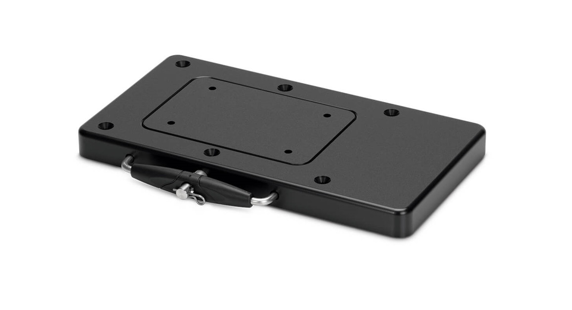
MKA-21/RTA-17QUICK RELEASE BRACKET1854021 & 1854017
The MKA-21 is recommended for use with Minn Kota® Ulterra™, Terrova®, PowerDrive™, PowerDrive V2, and Pontoon PowerDrive™ freshwater trolling motors and the Deckhand 40. The RTA-17 is recommended for use with Minn Kota® RT Ulterra™, RT Terrova®, RT PowerDrive™, and RT PowerDrive V2 saltwater trolling motors. Do not use motors equipped with a shaft 72” or greater. Do not use 112lb thrust motors.
| Item /Assembly | Part # | Description | Qty. |
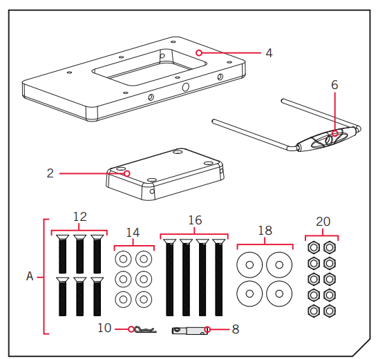
| 2 | 2371965 | PLATE-INNER PD/AP QCK REL. | 1 |
| 2371966 | PLATE-INNER PD/AP QRB BLK. | 1 | |
| 4 | 2371967 | PLATE-OUTER PD/AP QCK REL. | 1 |
| 2371968 | PLATE-OUTER PD/AP QRB BLK. | ||
| 6 | 2990906 | HANDLE ASSY PD/AP QRB. | 1 |
| AIncludes 8-20 | 2994848 | BAG ASSY PD/AP QRB | 1 |
| 8 | 2372631 | PIN-PADLOCK PD/AP QCK REL. | 1 |
| 10 | 2260800 | CLIP-HAIR SPRING,SS,MAX BG | 1 |
| 12 | 2373480 | SCREW-1/4-20 X 1 1/2 PFH SS | 6 |
| 14 | 2371712 | WASHER-FLAT 9/32 X 5/8 X 1/16 | 6 |
| 16 | 2373482 | SCREW-1/4-20 X 3″ PFH SS | 4 |
| 18 | 2261713 | WASHER-1/4 FLAT 18-8 SS | 4 |
| 20 | 2073100 | NUT-HEX 1/4-20 NYLOC-JAM SS | 10 |
| • | 2374917 | INSTRUCTIONS PD/AP QRB | 1 |
✖ Not shown on Parts Diagram.▲ This part is included in an assembly and cannot be ordered individually.
TOOLS AND RESOURCES REQUIRED
- Drill
- Drill bit 17/ 64”
- #2 or #3 Philips Screwdriver
- Awl, pencil or similar marking tool
- Scissors
- A second person to help with the installation
NOTICE: Do not use with motors equipped with a shaft 72” or greater. Do not use with 112lb thrust motors.NOTICE: Images are a graphical representation and may vary from your motor. Save the box! A template for installation is printed on the inside of the box.NOTICE: It is recommended to have a second person help with this installation.
MOUNTING CONSIDERATIONS
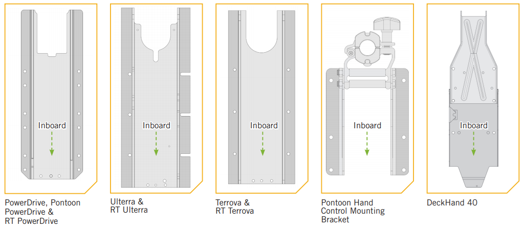
The MKA-21 is designed to be compatible with the Ulterra™, Terrova®, PowerDrive™, PowerDrive V2, and Pontoon PowerDrive™ Minn Kota® freshwater motors, and the Deckhand 40. The RTA-17 is designed to be compatible with the RT Ulterra™, RT Terrova®, RT PowerDrive™, RT PowerDrive V2 Minn Kota® saltwater motors. The base extrusion or mounting bracket of the trolling motors may vary.Please note the appearance of the applicable trolling motors and mounting brackets. For a complete list of motors compatible with the MKA-21 and RTA-17, please refer to the website at minnkotamotors.com.
The mounting location of the Quick Release Bracket will vary depending on the motor that will be mounted:
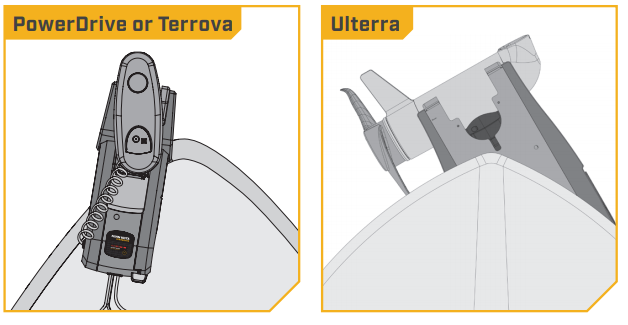
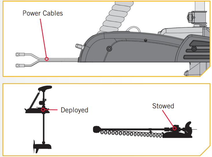
- For PowerDrive or Terrova motors: Fully deploy the motor and position the bracket on the bow of your boat to check for proper clearance. The motor must not encounter any obstructions as it is lowered into the water or raised into the boat.

- For Ulterra Motors: Position the bracket so the notch in the base is positioned beyond the gunwale of the boat. For proper clearance, the entire notch must be visible beyond the gunwale.The Ulterra motor cannot be deployed before mounting and connecting to a power source.
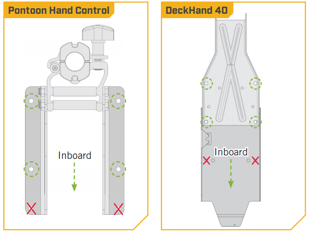
- For the DeckHand 40 and Pontoon Hand Control Bracket: Mount the bracket using only the four holes that are farthest outboard.
 The Ulterra motor cannot be deployed before mounting and connecting to a power source.
The two holes closest inboard are not used to install the bracket. It is recommended that the motor be mounted as close to the centerline of the boat as possible. The motor must not encounter any obstructions as it is lowered into the water or raised into the boat when stowed and deployed. Make sure the motor rest is positioned far enough beyond the edge of the boat. Make sure the area under the mounting location is flat, clear to drill holes and install nuts and washers. Recruit a second person to help with the installation, as an unsecured motor will tip when deployed and when left unattended.
Positioning the Bracket
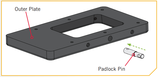
- ITEM(S) NEEDEDa. Take the Outer Plate (Item #4), Inner Plate (Item #2), Handle Assembly (Item #6), and Pad Lock Pin (Item #8). Assemble the bracket and place it on the deck of the boat.b. Determine if the motor will be mounted on the Port or Starboard side of the bow and if the Handle Assembly will release inboard or outboard. Be sure that the Handle Assembly will not encounter any obstructions on the bow of the boat and can be completely pulled out to release the plates when mounted. The bracket is designed so that the handle can be positioned on either side to accommodate clearances and personal preferences. The side of the bracket that the Handle Assembly is used on will determine which side the Padlock Pin (Item #8) will be installed on.NOTICE: Make sure that the motor will not encounter any obstructions when positioning the motor on and off the composite bracket. The exact placement of the motor and bracket, when mounting may vary depending on the boat, boat deck, and which base extrusion or bracket the bracket is being mounted to.NOTICE: The Lock Pin must be in place before installing the Outer Plate to the motor.c. Once an orientation for the Handle Assembly is selected, place the Padlock Pin into the Outer Plate on that side, oriented so that the larger diameter of the Pin is in the Outer Plate. Rotate the Pin so that the hole in the Pin lines up with the hole in the Outer Plate.
 a. Take the Outer Plate (Item #4), Inner Plate (Item #2), Handle Assembly (Item #6), and Pad Lock Pin (Item #8). Assemble the bracket and place it on the deck of the boat.
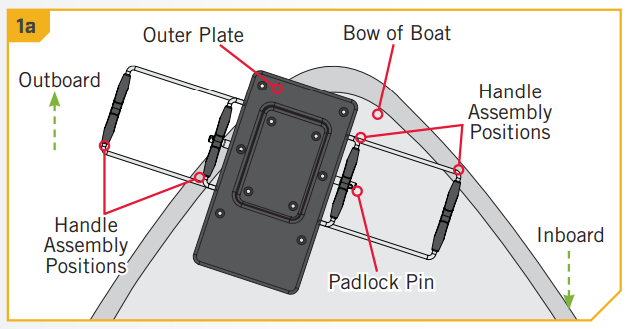 b. Determine if the motor will be mounted on the Port or Starboard side of the bow and if the Handle Assembly will release inboard or outboard. Be sure that the Handle Assembly will not encounter any obstructions on the bow of the boat and can be completely pulled out to release the plates when mounted. The bracket is designed so that the handle can be positioned on either side to accommodate clearances and personal preferences. The side of the bracket that the Handle Assembly is used on will determine which side the Padlock Pin (Item #8) will be installed on.
 NOTICE: Make sure that the motor will not encounter any obstructions when positioning the motor on and off the composite bracket. The exact placement of the motor and bracket, when mounting may vary depending on the boat, boat deck, and which base extrusion or bracket the bracket is being mounted to.NOTICE: The Lock Pin must be in place before installing the Outer Plate to the motor.c. Once an orientation for the Handle Assembly is selected, place the Padlock Pin into the Outer Plate on that side, oriented so that the larger diameter of the Pin is in the Outer Plate. Rotate the Pin so that the hole in the Pin lines up with the hole in the Outer Plate.
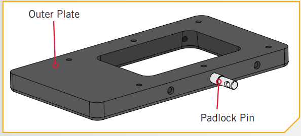
Installing the Outer Plate to a PowerDrive or Terrova
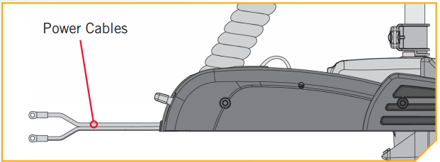
- WARNINGMake sure that the Power Cables from the battery are disconnected, or that the breaker, if equipped, is “off.”NOTICE: A motor may weigh up to 65lbs. We recommend having a second person help with the installation.a. Place the mount on an elevated, level surface such as a workbench or the tailgate of a pickup. The motor should be in the stowed position.
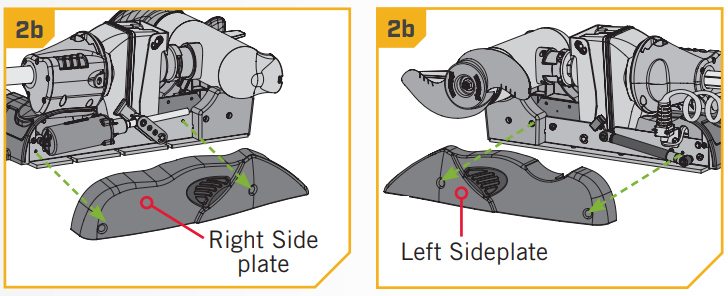
- b. Remove the four side plate screws using a #3 Phillips screwdriver. Two of these screws will be located on each side of the mount.c. Remove the Right Sideplate.d. Swing the Left Sideplate out and away from the Base Extrusion. Removing the sideplates exposes the Mounting Holes in the Base Extrusion.
- ITEM(S) NEEDEDe. Align the Outer Plate with the Base Extrusion.Position the Outer Plate so that the widest portion is facing inboard.f. Use six ¼” x 1½” Stainless Steel Screws (Item #12), six Flat Washers (Item #14) and six Nylock Nuts (Item #20) to fasten the Outer Plate to the bottom of the base extrusion. The Screws should pass from the bottom of the Outer Plate and then through the Base Extrusion. Place a Flat Washer on the end of each bolt and then secure each Screw with a Nylock Nut.g. Re-install both side covers. Secure the Screws using a #3 Phillips Screwdriver.
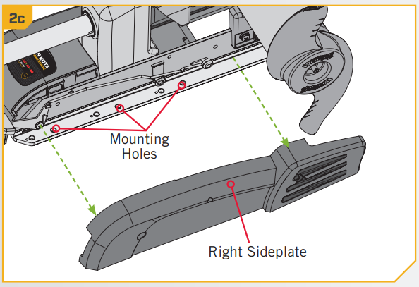 d. Swing the Left Sideplate out and away from the Base Extrusion. Removing the sideplates exposes the Mounting Holes in the Base Extrusion.
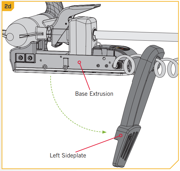
 e. Align the Outer Plate with the Base Extrusion.Position the Outer Plate so that the widest portion is facing inboard.f. Use six ¼” x 1½” Stainless Steel Screws (Item #12), six Flat Washers (Item #14) and six Nylock Nuts (Item #20) to fasten the Outer Plate to the bottom of the base extrusion. The Screws should pass from the bottom of the Outer Plate and then through the Base Extrusion. Place a Flat Washer on the end of each bolt and then secure each Screw with a Nylock Nut.
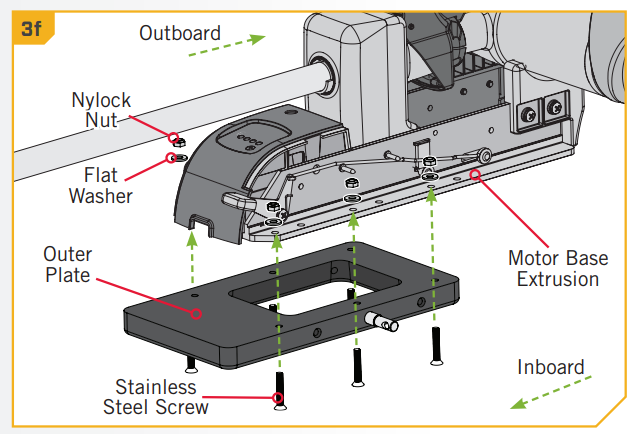 g. Re-install both side covers. Secure the Screws using a #3 Phillips Screwdriver.
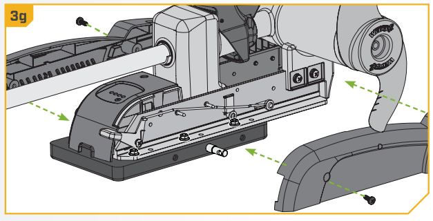
Installing the Outer Plate to a DeckHand 40
- ITEM(S) NEEDEDa. Position the DeckHand 40 Davit and Base over the Outer Plate (Item #4) and mount the Bracket using only the four holes that are the farthest Outboard. The two holes closest inboard are not used to install the Bracket.b. Take four ¼” x 1½” Stainless Steel Screws (Item #12) and insert them from the bottom of the Outer Plate through the DeckHand 40. Secure each Screw with a Flat Washer (Item #14) and a Nylock Nut (Item #20).
 a. Position the DeckHand 40 Davit and Base over the Outer Plate (Item #4) and mount the Bracket using only the four holes that are the farthest Outboard. The two holes closest inboard are not used to install the Bracket.
 b. Take four ¼” x 1½” Stainless Steel Screws (Item #12) and insert them from the bottom of the Outer Plate through the DeckHand 40. Secure each Screw with a Flat Washer (Item #14) and a Nylock Nut (Item #20).
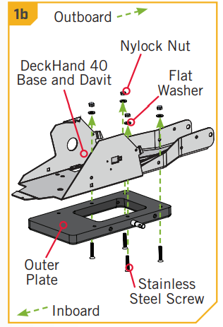
Installing the Outer Plate to a Pontoon Hand Control Bracket
- ITEM(S) NEEDEDa. Position the Pontoon Hand Control Bracket over the Outer Plate (Item #4) and mount the Bracket using only the four holes that are the farthest Outboard.The two holes closest inboard are not used to install the Bracket.b. Take four ¼” x 1½” Stainless Steel Screws (Item #12) and insert them from the bottom of the Outer Plate through the Pontoon Hand Control Bracket. Secure each Screw with a Flat Washer (Item #14) and a Nylock Nut (Item #20).
 a. Position the Pontoon Hand Control Bracket over the Outer Plate (Item #4) and mount the Bracket using only the four holes that are the farthest Outboard.The two holes closest inboard are not used to install the Bracket.
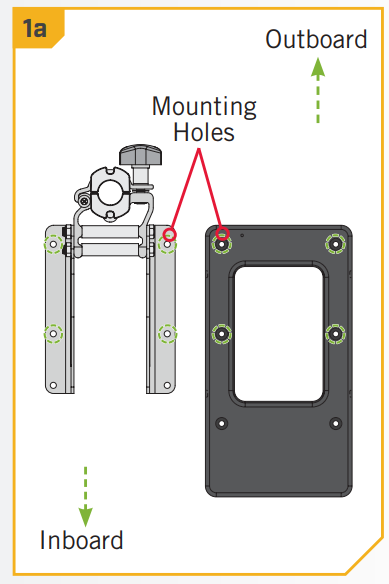 b. Take four ¼” x 1½” Stainless Steel Screws (Item #12) and insert them from the bottom of the Outer Plate through the Pontoon Hand Control Bracket. Secure each Screw with a Flat Washer (Item #14) and a Nylock Nut (Item #20).
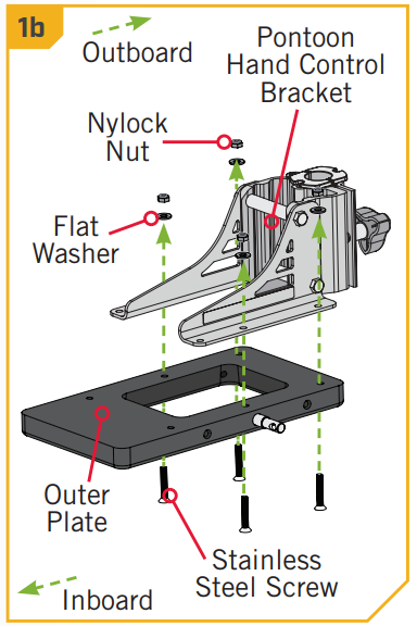
Installing the Outer Plate to an Ulterra
- WARNINGMake sure that the Power Cables from the battery are disconnected, or that the breaker, if equipped, is “off.”NOTICE: A motor may weigh up to 65lbs. We recommend having a second person help with the installation.a. Place the mount on an elevated, level surface such as a workbench or the tailgate of a pickup. The motor should be in the stowed position.NOTICE: Ulterra installation will use hardware that was included with the Ulterra motor. The hardware needed will be six Clipped Washers (#2201725) from the Ulterra bag assembly (#2994917). WARNINGDo not deploy the motor until it is fully mounted to the boat.Illustrations are for reference only. Deploying your motor before it is mounted to the boat may cause injury.
- b. Using a #2 Phillips Screwdriver, remove the Sideplates to access the Mounting Slots by removing the two screws that hold each side plate in place.
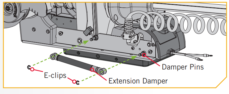
- c. Under the Left Sideplate, the Extension Damper obstructs access to the left front Mounting Hole.d. Using a small Screw Driver, remove the two 5/16″ e-clips holding the Extension Damper in place. Once the e-clips are removed, slide the Extension Damper off the Damper Pins to expose the left rear Mounting Hole. Set the two e-clips and Extension Damper in a safe place so they are not misplaced before they are reassembled later in the installation.
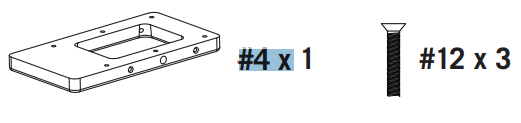
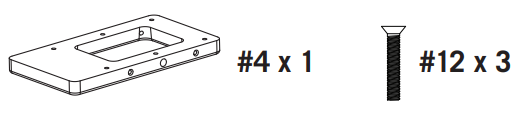
- ITEM(S) NEEDEDNOTICE: The Flat Washers (Item #14) and Nylock Nuts (Item #20) that came with the Quick Release Bracket are not sed when installing the MKA-21/RTA-17 to an Ulterra. The Stainless Steel Screws (Item #12) will still be used. Instead, the lipped Washers (#2201725) included in the mounting hardware that came with the Ulterra motor should be used.NOTICE: To prevent seizing of the stainless steel hardware, do not use high-speed installation tools. Wetting the screws or applying an anti-seize may help prevent seizing.e. Using three of the Stainless Steel Screws (Item #12) that came with the MKA-21/RTA-17, fasten the Outer Plate to the Base Extrusion. The Screws should pass from the bottom of the Outer Plate and then through the Base Extrusion. Takethree of the Clipped Washers (#2201725) that came with the Ulterra and place one on each screw. Orientate the Clipped Washers so that the flat side of the washer is towards the Base Extrusion.CAUTIONUse extra care to avoid pinching and damaging the sensor wires that run alongside of the Base Extrusion when installing and tightening the motor mounting screws.
- ITEM(S) NEEDEDf. Place the hardware on the Damper side of the mount into the Mounting Holes to secure the Base Extrusion.g. Fasten the Outer Plate with three Stainless Steel Screws (Item #12) and three Clipped Washers (#2201725). Orientate the Clipped Washers so that the flat side of the washer is towards the Base Extrusion. The Screws should be inserted upwards so that they pass through the Outer Plate, Base Extrusion and Clipped Washers.
- h. The Motor can now be reassembled. Slide the Extension Damper back in place on the Damper Pins.This should be done so the shaft on the Damper is pointing inboard. Reinstall the two 5/16” E-clips.i. Replace the Right Sideplate.
- j. Replace the Left Sideplate.k. Replace the four side plate Screws using a #2 or #3 Phillips Screw Driver.
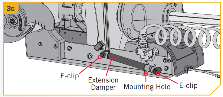 d. Using a small Screw Driver, remove the two 5/16″ e-clips holding the Extension Damper in place. Once the e-clips are removed, slide the Extension Damper off the Damper Pins to expose the left rear Mounting Hole. Set the two e-clips and Extension Damper in a safe place so they are not misplaced before they are reassembled later in the installation.
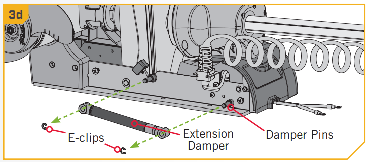
 NOTICE: The Flat Washers (Item #14) and Nylock Nuts (Item #20) that came with the Quick Release Bracket are not sed when installing the MKA-21/RTA-17 to an Ulterra. The Stainless Steel Screws (Item #12) will still be used. Instead, the lipped Washers (#2201725) included in the mounting hardware that came with the Ulterra motor should be used.NOTICE: To prevent seizing of the stainless steel hardware, do not use high-speed installation tools. Wetting the screws or applying an anti-seize may help prevent seizing.e. Using three of the Stainless Steel Screws (Item #12) that came with the MKA-21/RTA-17, fasten the Outer Plate to the Base Extrusion. The Screws should pass from the bottom of the Outer Plate and then through the Base Extrusion. Takethree of the Clipped Washers (#2201725) that came with the Ulterra and place one on each screw. Orientate the Clipped Washers so that the flat side of the washer is towards the Base Extrusion.
 f. Place the hardware on the Damper side of the mount into the Mounting Holes to secure the Base Extrusion.
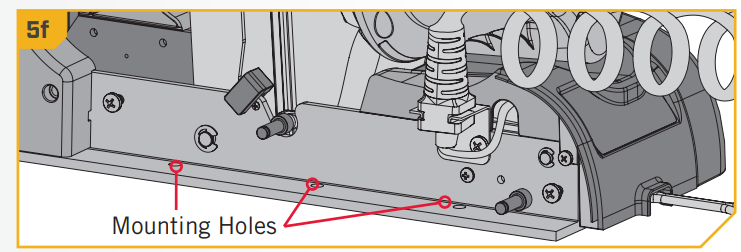 g. Fasten the Outer Plate with three Stainless Steel Screws (Item #12) and three Clipped Washers (#2201725). Orientate the Clipped Washers so that the flat side of the washer is towards the Base Extrusion. The Screws should be inserted upwards so that they pass through the Outer Plate, Base Extrusion and Clipped Washers.
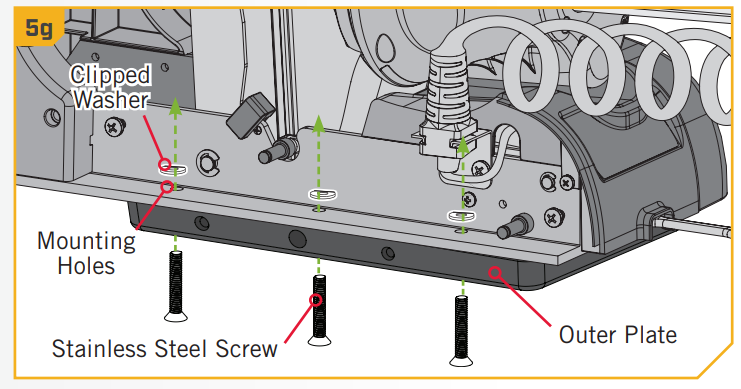
 i. Replace the Right Sideplate.
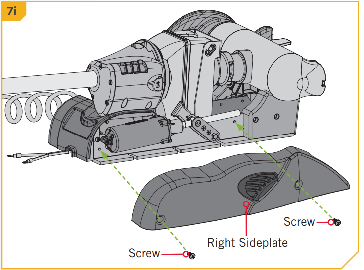
 k. Replace the four side plate Screws using a #2 or #3 Phillips Screw Driver.
Installing the Inner Plate to the Bow
- a. Place the Outer Plate with the motor attached as close to the centerline or keel of the boat as possible. Make sure to check clearance of the most bracket and handle for any possible obstructions othe bow of the boat.b. Check placement with the motor in the stowed and deployed positions if applicable for your motor.When the motor is in the deployed position, make sure that the Shaft is 1-1/2” out past the Gunnel of the boat. The lower unit, when stowed and deployed, must not encounter any obstructions.NOTICE: Due to variations in boat mounting surfaces, shims under the Inner Plate may be required. If the Inner Plate is not mounted flat, the Handle Assembly will not slide in properly.
- c. Mark the rear and side edges of the Outer Plate on the bow of your boat. These markings will be used to position a template that will be used to mark and drill the holes for the Inner Plate.d. Set the motor aside.e. Take the box that the Quick Release Bracket came in and carefully pull the glued edges apart and open the box so that it lays flat. On the inside of the box, a template is printed to help locate, mark, and drill the holes for the Inner Plate. Cut the template out and place it on the bow. Align it with the markings that were made while checking the handle and motor clearances. Make sure that the orientation of The outer Plate in the template matches the orientation of the Outer Plate as it is attached to the Motor.
- f. Locate the four mounting holes in the templateg. Drill the holes to a 17/64” diameter.
- ITEM(S) NEEDEDh. Place the Inner Plate on the bow of the boat and align it with the holes that were drilled using the template as a guide. For the best fit, it is recommended that the mounting surface under the Inner Plate is completely flat. Use shims or rubber washers to level the mounting surface if needed.If the Inner Plate is not mounted flat, the Handle Assembly will not slide properly.i. Fasten the Inner Plate to the bow of the boat using four ¼”- 20 x 3” Stainless Steel Screws (Item #16), four Flat Washers (Item #18), and four Nylock Nuts (Item #20). The Screws should pass through the Inner Plate, then the Bow, then the Flat Washers and Nylock Nuts.NOTICE: If the Handle Assembly does not slide easily into place after completing the installation, it may be necessary to drill out the Handle Rod Holes using a letter “F” (.257”) drill bit.
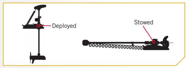
 b. Check placement with the motor in the stowed and deployed positions if applicable for your motor.When the motor is in the deployed position, make sure that the Shaft is 1-1/2” out past the Gunnel of the boat. The lower unit, when stowed and deployed, must not encounter any obstructions.
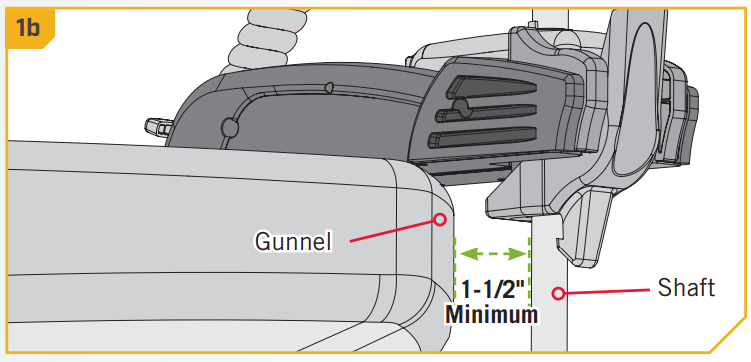 NOTICE: Due to variations in boat mounting surfaces, shims under the Inner Plate may be required. If the Inner Plate is not mounted flat, the Handle Assembly will not slide in properly.
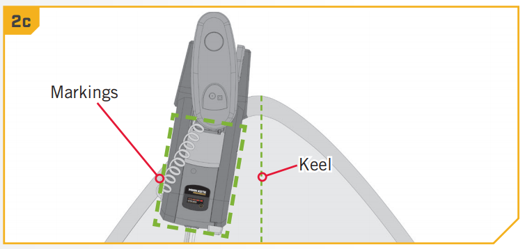 d. Set the motor aside.e. Take the box that the Quick Release Bracket came in and carefully pull the glued edges apart and open the box so that it lays flat. On the inside of the box, a template is printed to help locate, mark, and drill the holes for the Inner Plate. Cut the template out and place it on the bow. Align it with the markings that were made while checking the handle and motor clearances. Make sure that the orientation of The outer Plate in the template matches the orientation of the Outer Plate as it is attached to the Motor.
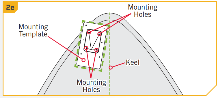
 g. Drill the holes to a 17/64” diameter.
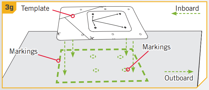
 h. Place the Inner Plate on the bow of the boat and align it with the holes that were drilled using the template as a guide. For the best fit, it is recommended that the mounting surface under the Inner Plate is completely flat. Use shims or rubber washers to level the mounting surface if needed.If the Inner Plate is not mounted flat, the Handle Assembly will not slide properly.i. Fasten the Inner Plate to the bow of the boat using four ¼”- 20 x 3” Stainless Steel Screws (Item #16), four Flat Washers (Item #18), and four Nylock Nuts (Item #20). The Screws should pass through the Inner Plate, then the Bow, then the Flat Washers and Nylock Nuts.
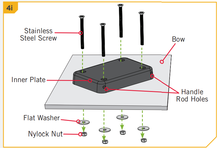 NOTICE: If the Handle Assembly does not slide easily into place after completing the installation, it may be necessary to drill out the Handle Rod Holes using a letter “F” (.257”) drill bit.
Completing the Installation
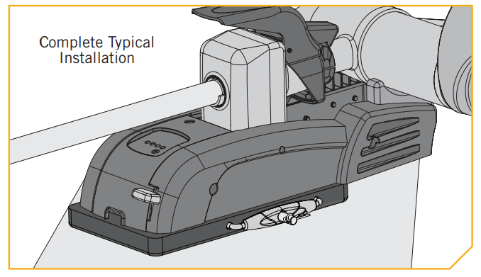
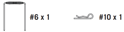
- ITEM(S) NEEDEDa. Mount the motor onto the Inner Plate.b. Slide the Handle Assembly (Item #6) into the rod holes of the Outer Plate. Slide the Hair Clip Pin (Item #10) through the Lock Pin to secure the Handle Assembly.c. Your motor is now mounted. Always make sure the Handle Assembly is fully inserted and retained by the Hair Clip Pin.NOTICE: A padlock can be used in place of the Hair Clip Pin to prevent motor theft.
 a. Mount the motor onto the Inner Plate.
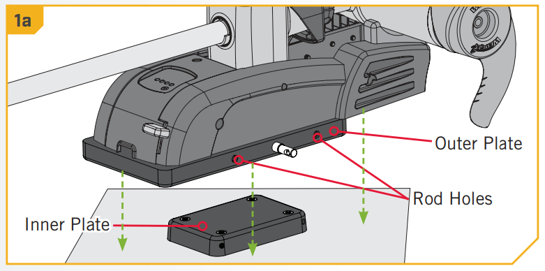 b. Slide the Handle Assembly (Item #6) into the rod holes of the Outer Plate. Slide the Hair Clip Pin (Item #10) through the Lock Pin to secure the Handle Assembly.
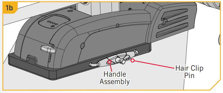 c. Your motor is now mounted. Always make sure the Handle Assembly is fully inserted and retained by the Hair Clip Pin.NOTICE: A padlock can be used in place of the Hair Clip Pin to prevent motor theft.
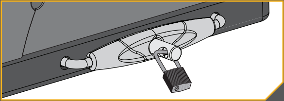
![]()
Minn Kota Consumer & Technical ServiceJohnson Outdoors Marine Electronics, Inc.PO Box 8129Mankato, MN 56001
121 Power DriveMankato, MN 56001Phone (800) 227-6433Fax (800) 527-4464
![]()
©2021 Johnson Outdoors Marine Electronics, Inc.All rights reserved.
Part #2374917ECN 41450Rev H04/21
[xyz-ips snippet=”download-snippet”]