![]()
PRECISION ONBOARDCHARGERSMK 106PCL, MK 212PCL, MK 318PCL, MK 110PCL,MK 220PCL, MK 330PCL, MK 440PCL & MK 550PCLOwner’s Manual
THANK YOUThank you for choosing Minn Kota ® . We believe that you should spend more time fishing and less time positioning your boat. That’s why we build the smartest, toughest, most intuitive marine products on the water. Every aspect of a Minn Kota product is thought out and rethought until it’s good enough to bear our name. Countless hours of research and testing provide you the advantages of a Minn Kota product that can truly take you “Anywhere. Anytime”. We don’t believe in shortcuts. We are Minn Kota. And we are never done helping you catch more fish.
REGISTRATIONRemember to keep your receipt and immediately register your charger. To receive all the benefits of your product warranty, please fill out and mail the registration card. You may also register your product online at minnkotamotors.com.
SERIAL NUMBERYour Minn Kota 11-character serial number is very important. It helps to determine the specific model and year of manufacture.When contacting Consumer Service or registering your product, you will need to know your product’s serial number. We recommend that you write the serial number down so that you have it available for future reference.
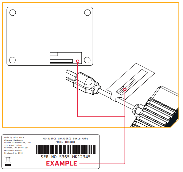
NOTICE: The serial number on your Precision Charger is located on the bottom of the charger and on the Warning Decal on the AC Power Cord.
PRODUCT INFORMATION(For Consumer Reference Only)Model: __________________________________________Serial Number: ____________________________________Purchase Date: ____________________________________Store Where Purchased: _____________________________
NOTICE: Do not return your Minn Kota product to your retailer. Your retailer is not authorized to repair or replace this unit. Youmay obtain service by: calling Minn Kota at (800) 227-6433; returning your charger to the Minn Kota Factory Service Center; sending or taking your product to any Minn Kota authorized service center. A list of authorized service centers is available on our website, at minnkotamotors.com. Please include proof of purchase, serial number and purchase date for warranty service with any of the above options.
SAFETY INSTRUCTIONS
IMPORTANT SAFETY INSTRUCTIONS – SAVE THESE INSTRUCTIONS
- SAVE THESE INSTRUCTIONS – This manual contains important safety and operating instructions for your Minn Kota battery charger.The Minn Kota battery charger is a powerful electrical device. If incorrectly installed, configured or operated, the battery charger can damage batteries and/or electrical equipment. Please thoroughly read the instructions and safety information contained in this manual before operating the battery charger.
- Use of an attachment not recommended or sold by Johnson Outdoors Marine Electronics, Inc. may result in a risk or fire, electric shock, or injury to persons.
- To reduce the risk of damage to the electric plug and cord, pull by plug rather than cord when disconnecting charger.
- An extension cord should not be used unless absolutely necessary. Use of improper extension cord could result in a risk of fire and electric shock. If an extension cord must be used, make sure:a) That pins on plug of extension cord are the same number, size, and shape as those of plug on the charger;b) That extension cord is properly wired and in good electrical condition, andc) That wire size is large enough for ac ampere rating of charger as specified in the table.
Model AWG Size 25′ AC Extension Cord 50′ AC Extension Cord 100′ AC Extension Cord MK 1O6PCL 18 AWG 18 AWG 16 AWG MK 212PCL 18AWG 18AWG 16AWG MK 318PCL 16AWG 16AWG 12AWG MK 11OPCL 18 AWG 18 AWG 16 AWG MK 22OPCL 16AWG 16AWG 12AWG MK 330PCL 16AWG 16AWG 12AWG MK 440PCL 16 AWG 12 AWG 10 AWG MK 55OPCL 14 AWG 12AWG 10 AWG - Do not operate charger with damaged cord or plug.
- Do not operate the charger if it has received a sharp blow, been dropped, or otherwise damaged in any way. Do not operate the charger with a damaged cord or plug – replace the charger immediately.
- Do not disassemble the charger.
- To reduce risk of electric shock, unplug the charger from the outlet and disconnect from the battery before attempting any maintenance or cleaning. Turning off controls will not reduce this risk.
 WARNING
 - WARNING – RISK OF EXPLOSIVE GASESa) WORKING IN VICINITY OF A LEAD-ACID BATTERY IS DANGEROUS. BATTERIES GENERATE EXPLOSIVE GASES DURING NORMAL BATTERY OPERATION. FOR THIS REASON, IT IS OF UTMOST IMPORTANCE THAT YOU FOLLOW THE INSTRUCTIONS EACH TIME YOU USE THE CHARGER.b) To reduce the risk of battery explosion, follow these instructions and those published by the battery manufacturer and manufacturer of any equipment you intend to use in the vicinity of the battery. Review cautionary markings on these products and on the engine.
- External connections to the charger shall comply with the United States Coast Guard Electrical Regulation (33CFR183, SUBPART 1).For safety and compliance reasons, we recommend that you follow American Boat and Yacht Council (ABYC) standards when rigging your boat. Altering boat wiring should be completed by a qualified marine technician.
- PERSONAL PRECAUTIONSa) Consider having someone close enough by to come to your aid when you work near a lead-acid battery.b) Have plenty of fresh water and soap nearby in case acid contacts skin, clothing, or eyes.c) Wear complete eye protection and clothing protection. Avoid touching eyes while working near the battery.d) If battery acid contacts skin or clothing, wash immediately with soap and water. If acid enters the eyes, immediately flood eye withrunning cold water for at least 10 minutes and get medical attention immediately.e) NEVER smoke or allow a spark or flame in the vicinity of the battery or engine.f) Be extra cautious to reduce the risk of dropping a metal tool onto the battery. It might spark or short-circuit a battery or another electrical part that may cause an explosion.g) Remove personal metal items such as rings, bracelets, necklaces, and watches when working with a lead-acid battery. A lead-acidthe battery can produce a short-circuit current high enough to weld a ring or the like to metal, causing a severe burn.h) Use a charger for charging batteries only. It is not intended to supply power to a low voltage electrical system other than in a starter motor application. Do not use a battery charger for charging dry-cell batteries that are commonly used with home appliances.These batteries may burst and cause injury to persons and damage to property.i) NEVER charge a frozen battery.
- PREPARING TO CHARGEa) If necessary to remove the battery from boat or vehicle to charge, always remove grounded terminal from battery first. Make sure all accessories in the boat or vehicle are off, so as not to cause an arc.b) Be sure area around the battery is well ventilated while the battery is being charged.c) Clean battery terminals. Be careful to keep corrosion from coming in contact with eyes.d) add distilled water to each cell until battery acid reaches the level specified by the battery manufacturer. Do not overfill. For a battery without removable cell caps, such as valve-regulated lead-acid batteries, carefully follow the manufacturer’s recharging instructions.e) Study all battery manufacturer’s specific precautions while charging and recommended rates of charge.f) The Minn Kota charger will only charge 12 Volt/6 Cell Lead-acid Batteries (Flooded, Maintenance Free, or AGM) and 12 Volt Lithium (LiFePO4 )Batteries (check battery manufacturer’s specifications). Do not connect the output of the charger to any othera voltage or battery type.
- CHARGER LOCATIONa) Locate charger as far away from battery as dc cables permit.b) Never place charger directly above battery being charged; gases from battery will corrode and damage the charger.c) Never allow battery acid to drip on the charger when reading electrolyte specific gravity or filling battery.d) Do not operate charger in a closed-in area or restrict ventilation in any way.e) Do not set a battery on top of the charger.
SAFETY INSTRUCTIONS
f) Do not mount the charger below the waterline of the boat or directly adjacent to fuel tanks.g) Each DC output cord is six feet long. Make sure that all DC output cords can reach the batteries and that the AC power cord can reach a power source. When using an extension cord, make the AC connection to the charger outside of the battery compartment as far away as practical to reduce the risk of a spark igniting gases in the compartment.h) Do not shorten the DC output cords, as this can affect charger output.i) If the DC output cords are not long enough, they may be lengthened by splicing and soldering 12 AWG (minimum) wire. Each splice should be covered with dual wall adhesive-lined heat shrink tubing to protect the joint from corroding. The splice should be made between the fork in the output cable and the fuse holder. The fuse holder should always remain within 7” of the battery terminals. The maximum extension length is 15 feet. You may contact the Minn Kota Service Department with any questions.
WARNINGj) Do not splice the AC power cord, as this voids the three-year Limited Warranty.k) Even though the Minn Kota charger is capable of operating in a high ambient temperature environment, a minimum of six inches of the unobstructed area should be allowed on all sides of the unit for proper air circulation and cooling. Proper cooling and circulation will allow the charger to operate at peak efficiency.l) Keyhole slots are not to be used for installing the charger. - MOUNTING THE CHARGER – Due to the weight of the charger and the impact that boats routinely endure, take the time to securely mount the charger to prevent damage. Mounting with nuts, bolts and washers is preferable to mounting with screws.a) Charger was designed to be mounted in any orientation on the boat.b) Use the largest diameter bolts possible and use all four mounting holes.c) After marking the locations, set the charger aside and drill the holes.d) Apply a marine-grade silicone sealant in each of the drilled holes to create a waterproof seal.e) Then secure the charger in place using the mounting hardware.NOTICE: Your battery charger is supplied with an AC plug holder designed to hold the power cord plug when not in use. Mount the AC plug holder with four screws in a convenient dry site to prevent corrosion to the AC plug and to prevent the AC plug from making contact with the battery posts. WARNINGf) Make sure the charger is disconnected from AC power before connecting the batteries to the output cords. CAUTIONg) Before making any connections to batteries in a confined space (such as a battery compartment of a boat), open the door or hatch of the compartment and allow it to air out for 15 minutes. This allows any gases that have accumulated in the compartment to escape.
- DC CONNECTION PRECAUTIONSa) Connect and disconnect dc output terminals only after removing accord from the electric outlet. Never allow output terminals to touch each other.b) Attach output terminals to battery and chassis as indicated in 16(e), 16(f), and 17(b).
- FOLLOW THESE STEPS WHEN THE BATTERY IS INSTALLED IN THE VEHICLE. A SPARK NEAR THE BATTERY MAY CAUSE THE BATTERY EXPLOSION. TO REDUCE RISK OF A SPARK NEAR BATTERY:a) Position ac and dc cords to reduce the risk of damage by hood, door, or moving engine part.b) Stay clear of fan blades, belts, pulleys. and other parts that can cause injury to persons.c) Check the polarity of battery posts. POSITIVE (POS, P, +) battery post usually has a larger diameter than NEGATIVE (NEG, N, -) post.d) Determine which post of battery is grounded (connected) to the chassis. If a negative post is grounded to chassis (as in most vehicles), see (e). If a positive post is grounded to the chassis, see (f).e) For negative-grounded vehicle, connect POSITIVE (RED) output terminal from battery charger to POSITIVE (POS, P, +) ungrounded post of the battery. Connect NEGATIVE (BLACK) output terminal to vehicle chassis or engine block away from the battery. Do not connect the output terminal to the carburetor, fuel lines, or sheet-metal body parts. Connect to a heavy gauge metal part of the frame or engine block. (Refer to Figure 1).f) For a positive-grounded vehicle, connect NEGATIVE (BLACK) output terminal from battery charger to NEGATIVE (NEG, N, -) ungrounded post of the battery. Connect POSITIVE (RED) output terminal to vehicle chassis or engine block away from the battery.Do not connect the output terminal to the carburetor, fuel lines, or sheet-metal body parts. Connect to a heavy gauge metal part of the frame or engine block. (Refer to Figure 2).g) When disconnecting the charger, disconnect the AC cord, remove the output terminal from the vehicle chassis, and then remove the output terminal from the battery terminal.h) See operating instructions for length of charge information.
SAFETY INSTRUCTIONS
- FOLLOW THESE STEPS WHEN THE BATTERY IS OUTSIDE THE VEHICLE. A SPARK NEAR THE BATTERY MAY CAUSE A BATTERY EXPLOSION. TO REDUCE RISK OF A SPARK NEAR BATTERY:a) Check the polarity of battery posts. POSITIVE (POS, P, +) battery post usually has a larger diameter than NEGATIVE (NEG, N, -) post.b) Connect POSITIVE (RED) output terminal to POSITIVE (POS, P, +) post of the battery. Connect NEGATIVE (BLACK) output terminal to NEGATIVE (NEG, N, -) post of the battery.c) Do not face battery when making final connection.d) When disconnecting the charger, always do so in the reverse sequence of the connecting procedure.e) A marine (boat) battery does not need to be removed and charged onshore. However, instructions must be followed for the location of the charger when permanently mounted or used onboard. DANGER
- DANGER – Never alter AC cord or plug provided – if it will not fit the outlet, have a proper outlet installed by a qualified electrician.Improper connection can result in a risk of an electric shock. DANGER
- DANGER – Do not attempt to repair or service the charger yourself. Opening the charger may expose you to high voltages, the risk of electric shock, and other hazards. DANGER
- DANGER – Do not splice the AC power cord. CAUTION
- CAUTION – When using an extension cord, make the AC connection to the charger outside of the battery compartment as far away as practical to reduce the risk of a spark igniting gases in the compartment. CAUTION
- CAUTION – Even though the Minn Kota charger is capable of operating in a high ambient temperature environment, a minimum of six inches of the unobstructed area should be allowed on all sides of the unit for proper air circulation and cooling. Proper cooling and circulation will allow the charger to operate at peak efficiency. CAUTION
- CAUTION – Before making any connections to batteries in a confined space (such as a battery compartment of a boat), open the door or hatch of the compartment and allow it to air out for 15 minutes. This allows any gases that have accumulated in the compartment to escape. CAUTION
- CAUTION – We recommend that you not recharge your battery, with the watercraft or motor lower unit in the water during electrical storms. Severe damage to the motor or charging system may occur if lightning strikes nearby or if storm-related high voltage conditions exist. CAUTION
- CAUTION – If using a generator to power the charger, it must have a clean output and be safe for use on electrical equipment. Generators with a sine wave output can be used to power this charger. See the table in the Maintenance Instructions for power requirements. DANGER
- DANGER – Damaged cords and plugs can cause electric shock or electrocution. WARNING
- WARNING – Avoid serious injury or death from fire, explosion, or electric shock.• This device must be connected to a Ground Fault Circuit Interrupt (GFCI) protected AC outlet• When using an extension cord, connect the AC charger plug before connecting to the GFCI protected AC outlet• Make the connection in an open atmosphere free of explosive fumes• Make the connection in a secure manner that will avoid contact with the water
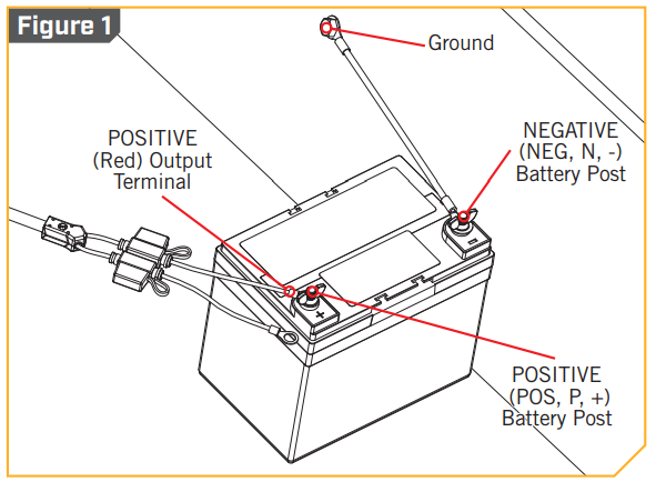 f) For a positive-grounded vehicle, connect NEGATIVE (BLACK) output terminal from battery charger to NEGATIVE (NEG, N, -) ungrounded post of the battery. Connect POSITIVE (RED) output terminal to vehicle chassis or engine block away from the battery.Do not connect the output terminal to the carburetor, fuel lines, or sheet-metal body parts. Connect to a heavy gauge metal part of the frame or engine block. (Refer to Figure 2).
 g) When disconnecting the charger, disconnect the AC cord, remove the output terminal from the vehicle chassis, and then remove the output terminal from the battery terminal.h) See operating instructions for length of charge information.
WARRANTY
WARRANTY ON MINN KOTA BATTERY CHARGERS AND BATTERY MAINTAINERSJohnson Outdoors Marine Electronics, Inc. (“JOME”) extends the following limited warranty to the original retail purchaser only. Warranty coverage is not transferable.Minn Kota Limited Three-Year Replacement Warranty on the Entire ProductJOME warrants to the original retail purchaser only that the purchaser’s new Minn Kota battery charger will be materially free from defects in materials and workmanship appearing within three (3) years after the date of purchase. JOME will (at its option) replace, free of charge, any charger found by JOME to be defective during the term of this warranty. Such replacement shall be the sole and exclusive liability of JOME and the sole and exclusive remedy of the purchaser for breach of this warranty.Exclusions & LimitationsThis limited warranty does not apply to products that have been commercially or for rental purposes. This limited warranty does not cover normal wear and tear, blemishes that do not affect the operation of the product, or damage caused by accidents, abuse, alteration, modification, shipping damages, acts of God, negligence of the user or misuse, improper or insufficient care or maintenance. DAMAGE CAUSED BY THE USE OF OTHER REPLACEMENT PARTS NOT MEETING THE DESIGN SPECIFICATIONS OF THE ORIGINAL PARTS WILL NOT BE COVERED BY THIS LIMITED WARRANTY. The cost of normal maintenance or replacement parts that are not in breach of the limited warranty are the responsibility of the purchaser. Prior to using products, the purchaser shall determine the suitability of the products for the intended use and assumes all related risk and liability. Any assistance JOME provides to or procures for the purchaser outside the terms, limitations or exclusions of this limited warranty will not constitute a waiver of the terms, limitations or exclusions, nor will such assistance extend or revive the warranty.JOME will not reimburse the purchaser for any expenses incurred by the purchaser in repairing, correcting or replacing any defective products or parts, except those incurred with JOME’s prior written permission. JOME’S AGGREGATE LIABILITY WITH RESPECT TO COVERED PRODUCTS IS LIMITED TO AN AMOUNT EQUAL TO THE PURCHASER’S ORIGINAL PURCHASE PRICE PAID FOR SUCH PRODUCT.How to Obtain Warranty ServiceTo obtain warranty service in the U.S., Contact Minn Kota Customer Service. Contact forms are available at www.minnkotamotors.com/contactor call 1-800-227-6433. After contact, it will be determined if a warranty replacement of the charger is required. Serial number and proof of the purchase will be required to arrange a warranty replacement.Products purchased outside of the U.S. must be returned prepaid with proof of purchase (including the date of purchase and serial number) to any Authorized Minn Kota Service Center in the country of purchase.Any charges incurred for service calls, transportation or shipping/freight to/from Minn Kota, labor to haul out, remove, re-install, or re-rig products removed for warranty service, or any other similar items are the sole and exclusive responsibility of the purchaser.Products replaced will be warranted for the remainder of the original warranty period, or for 90 days from the date of replacement, whichever is longer.Returns without prior contact to Minn Kota Customer Service may be subject to a charge for troubleshooting and evaluation at the prevailing posted labor rate and for a minimum of at least one hour.
NOTICE: Do not return your Minn Kota product to your retailer. Your retailer is not authorized to repair or replace products.NOTICE: THERE ARE NO EXPRESS WARRANTIES OTHER THAN THESE LIMITED WARRANTIES. IN NO EVENT SHALL ANY IMPLIED WARRANTIES INCLUDING ANY IMPLIED WARRANTIES OF MERCHANTABILITY OR FITNESS FOR A PARTICULAR PURPOSE, EXTEND BEYOND THE DURATION OF THE RELEVANT EXPRESS LIMITED WARRANTY. IN NO EVENT SHALL JOME BE LIABLE FOR PUNITIVE, INDIRECT, INCIDENTAL, CONSEQUENTIAL, OR SPECIAL DAMAGES. Without limiting the foregoing, JOME assumes no responsibility for loss of use of the product, loss of time, inconvenience or other damage.
How Does State Law Apply?Some states do not allow limitations on how long an implied warranty lasts or the exclusion or limitation of incidental or consequential damages, so the above limitations and/or exclusions may not apply to you. This warranty gives you specific legal rights and you may also have other legal rights which vary from state to state.
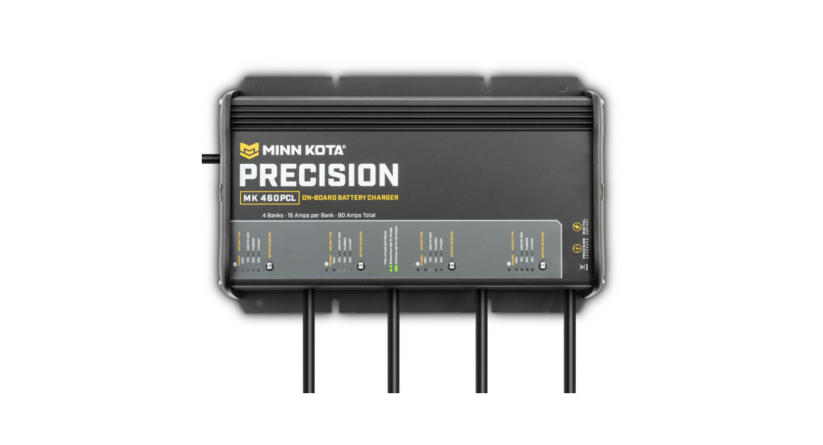
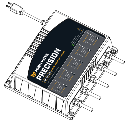
FEATURES
NOTICE: Specifications subject to change without notice. This diagram is for reference only and may differ from your actual product.
INSTALLATION
INSTALLATION AND MOUNTING
Please take the following recommendations into consideration when locating a mounting location and installing the charger.LOCATING A MOUNTING LOCATION FOR THE CHARGER
- Never place charger above battery being charged; gases from battery will corrode and damage the charger.
- Never allow battery acid to drip on the charger when reading electrolyte specific gravity or filling battery.
- Do not operate chargers in a closed-in area or restrict ventilation in any way.
- Do not set a battery on top of the charger.
- Do not mount the charger below the waterline of the boat or directly adjacent to fuel tanks.
- Each DC output cord is six feet long. Make sure that all DC output cords can reach the batteries and that the AC power cord can reach a power source. When using an extension cord, make the AC connection to the charger outside of the battery compartment as far away as practical to reduce the risk of a spark igniting gases in the compartment.
- Do not shorten the DC output cords, as this can affect charger output. If the DC output cords are not long enough, they may be lengthened by splicing and soldering 12 AWG (minimum) wire. Each splice should be covered with dual wall adhesive-lined heat shrink tubing to protect the joint from corroding. The splice should be made between the fork in the output cable and the fuse holder.The fuse holder should always remain within 7” of the battery terminals. The maximum extension length is 15 feet. You may contact the Minn Kota Service Department with any questions. WARNINGDo not splice the AC power cord, as this voids the three-year Limited Warranty.
- Even though the Minn Kota charger is capable of operating in a high ambient temperature environment, a minimum of six inches of the unobstructed area should be allowed on all sides of the unit for proper air circulation and cooling. Proper cooling and circulation will allow the charger to operate at peak efficiency.
MOUNTING THE CHARGERDue to the weight of the charger and the impact that boats routinely endure, take the time to securely mount the charger to prevent damage.Mounting with nuts, bolts and washers is preferable to mounting with screws.
- Use the largest diameter bolts possible and use all four mounting holes.
- After marking the locations, set the charger aside and drill the holes.
- Apply a marine-grade silicone sealant in each of the drilled holes to create a waterproof seal.
- Then secure the charger in place using the mounting hardware.
![]() WARNINGMake sure the charger is disconnected from AC power before connecting the batteries to the output cords.
WARNINGMake sure the charger is disconnected from AC power before connecting the batteries to the output cords.![]() CAUTIONBefore making any connections to batteries in a confined space (such as a battery compartment of a boat), open the door or hatch of the compartment and allow it to air out for 15 minutes. This allows any gases that have accumulated in the compartment to escape.NOTICE: Your battery charger is supplied with an AC plug holder designed to hold the power cord plug when not in use. Mount the AC plug holder with four screws in a convenient dry site to prevent corrosion to the AC plug and to prevent the AC plug from making contact with the battery posts.
CAUTIONBefore making any connections to batteries in a confined space (such as a battery compartment of a boat), open the door or hatch of the compartment and allow it to air out for 15 minutes. This allows any gases that have accumulated in the compartment to escape.NOTICE: Your battery charger is supplied with an AC plug holder designed to hold the power cord plug when not in use. Mount the AC plug holder with four screws in a convenient dry site to prevent corrosion to the AC plug and to prevent the AC plug from making contact with the battery posts.
INSTALLING THE MK-EC BATTERY CHARGER EXTENSION CABLEThe Minn Kota Battery Charger Extension Cables are ideal for extending charger output cables that do not reach the bow, center or transom battery compartments. Features easy installation with waterproof adhesive heat shrink for use in saltwater environments. Each conductor is fused for protection against accidental short circuits.NOTICE: The MK-EC Battery Charger Extension Cable (#1820089) is an optional kit that is NOT included with the charger.
INSTALLATION PARTS LIST
| Item /Assembly | Part # Description | Qty. | |
| 1 | ✖ | 15FT EXTENSION CABLE | 1 |
| 2 | ✖ | WIRE SPLICE | 2 |
| 3 | ✖ | ADHESIVE HEAT SHRINK | 2 |
✖ This part is included in an assembly and cannot be ordered individually.
TOOLS AND RESOURCES REQUIRED
- Wire Cutters
- Wire Strippers
- Crimpers
- Heat Gun
- a. Remove AC power from your charger and disconnect the charger from ALL batteries.b. Open the door or hatch of the compartment and allow it to air out for 15 minutes. This allows any gases that have accumulated in the compartment to escape.c. Find the Charger Output Cable you would like to extend and use the wire cutters to cut the red or white (positive) and black (negative) wires before the Fuse Holders.
- d. Remove the loose pieces of insulation from the ends of the Battery Charger Extension Cable wires and crimp the Black (Negative -) Wire into the Wire Splice connector using the crimpers.e. Strip the Battery Charger Output Cable wires 3/8” if they are 12AWG. Strip the Battery Charger Output Cable wires 3/4” if theyare 14AWG or 16AWG.f. Place one of the Adhesive Heat Shrinks over the Wire Splice and onto the Black (Negative -) Wire of the Battery Charger Extension Cable.g. For 12AWG wire, insert the Black (Negative -) Battery Charger Output Cable into the Wire Splice and crimp using the crimpers.For 14AWG or 16AWG wire, fold the stripped Black (Negative -) Battery Charger Output Cable wire in half before inserting andcrimping the wire.h. Center the Adhesive Heat Shrink over the Wire Splice. Using the heat gun, warm the Adhesive Heat Shrink until it seals the connection.i. Repeat steps d through h for connecting the Red or White (Positive +) Wires to the Wire Splice.j. Prepare each battery in advance by cleaning off dirt, oil, battery corrosion, etc. Use a water and baking soda solution for cleaning corrosion. Wipe using a dry cloth.k. Route the Battery Charger Extension Cable away from sharp objects. Do not remove the Fuse Holders, since fuses are locatedon both the Red (Positive +) and Black (Negative -) Wires for protection in case of a short circuit.l. Now connect the Battery Charger Extension Cable to the battery. Be sure to connect the Black (Negative -) Ring Terminal to the Negative (-) Battery Post and connect the Red (Positive +) Ring Terminal to the Positive (+) Battery Post.
OPERATING INSTRUCTIONS
OVERVIEW
This is a high-performance battery charger that has the ability to properly and safely work with 12 Volt/6 Cell Lead-acid Batteries that are Flooded, Maintenance Free and AGM or 12V Lithium (LiFePO4) (check battery manufacturer’s specifications) only. It is important to read and understand how to properly use the battery charger before charging batteries.Each Output Bank is independent and isolated from one another and the AC Input. The Minn Kota charger can charge independent batteries or combinations of batteries hooked in series or parallel without disconnecting the batteries from any switches or Jumper Wires joining the batteries.
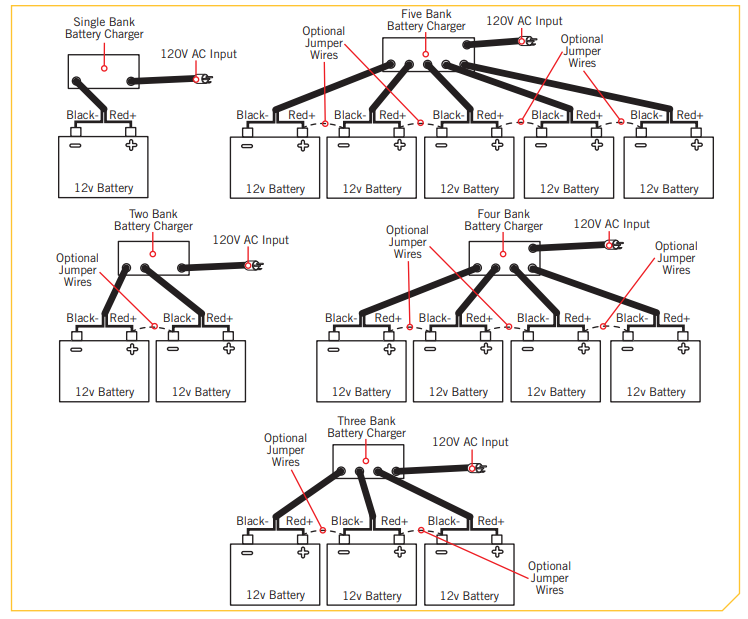
NOTICE: If batteries are connected in a series with Jumper Wires, those wires can be left in place during charging.
SELECTING THE BATTERY TYPEThe charger can be manually switched between 4 different modes:
- AGM/High-Performance AGM
- Flooded Lead-Acid
- Lithium (LiFePO4 )
- Equalize (for Flooded Lead-Acid)
In order to optimize the performance of your batteries or to prevent damage, you will need to properly set each charger bank for the correct battery type (each bank can be independently set). The factory default setting is Flooded Lead-Acid.
Setting the Battery Type
- a. Plug the charger AC cord into the AC outlet.b. During power up all LEDs will temporarily turn on, then just 1 YELLOW LED will remain on.This YELLOW LED will indicate the current battery type selected.c. To change battery type, press and hold the Battery Selection button until the YELLOW LED indicates the desired battery type, then release the button. The battery type will be saved even if the AC cord or DC output cords are disconnected.NOTICE: The battery type will be saved even if the AC cord or DC output cords are disconnected. When the charger is powered “on”, the battery type selected will be recalled from memory.
 b. During power up all LEDs will temporarily turn on, then just 1 YELLOW LED will remain on.This YELLOW LED will indicate the current battery type selected.
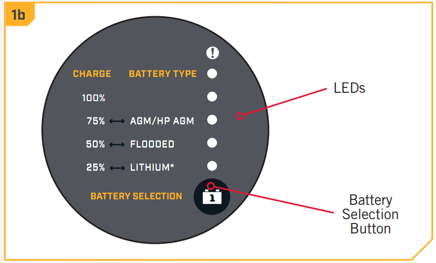 c. To change battery type, press and hold the Battery Selection
 ![]() WARNINGBattery type is factory preset for Flooded Lead-Acid. If you are using alternate type batteries, select Lithium (LiFePO4) or GM/High-Performance AGM. Failure to select the correct battery type could result in damage to your battery and/or cause acid leaks.Setting Equalize Mode for Flooded Lead-Acid BatteriesFlooded Lead-Acid batteries should be equalized per the battery manufacturers’ recommendations. Only Flooded Lead-Acid batteries should be equalized. The charger will only allow the selection of the Equalize Mode if the previous selection was Flooded Lead-Acid. To set Equalize Mode, press and hold the Battery Selection button until all 3 YELLOW LEDs are lit, then release the button. Once in Equalize Mode, the equalize process will only be performed one time. Once this cycle is completed or if the cycle is interrupted (by unplugging the AC or a DC cord), the charger will revert back to the Flooded Lead-Acid battery type.GENERAL OPERATION
WARNINGBattery type is factory preset for Flooded Lead-Acid. If you are using alternate type batteries, select Lithium (LiFePO4) or GM/High-Performance AGM. Failure to select the correct battery type could result in damage to your battery and/or cause acid leaks.Setting Equalize Mode for Flooded Lead-Acid BatteriesFlooded Lead-Acid batteries should be equalized per the battery manufacturers’ recommendations. Only Flooded Lead-Acid batteries should be equalized. The charger will only allow the selection of the Equalize Mode if the previous selection was Flooded Lead-Acid. To set Equalize Mode, press and hold the Battery Selection button until all 3 YELLOW LEDs are lit, then release the button. Once in Equalize Mode, the equalize process will only be performed one time. Once this cycle is completed or if the cycle is interrupted (by unplugging the AC or a DC cord), the charger will revert back to the Flooded Lead-Acid battery type.GENERAL OPERATION![]() WARNINGMake sure the charger is disconnected from AC power before connecting the batteries to the output cords.
WARNINGMake sure the charger is disconnected from AC power before connecting the batteries to the output cords.
After the AC cord on the charger is plugged in and a battery is connected to the output cable correctly, the 25% charging LED will turn on. After 2 seconds, the charger will begin charging the battery. The YELLOW LEDs will indicate how far the charger is in the charging process. Once the 100% GREEN LED is blinking, the charger is holding the float voltage. The charger will hold the batteries float voltagefor 24 hours. After 24 hours, the charger output will turn off and the 100% blinking GREEN LED will switch to steady GREEN. For specifics on Lithium Batteries, please see the “LED Patterns” section of this Manual.Lithium batteries can shut themselves off after extensive use under certain conditions. This protective condition is referred to as Standby Mode. Refer to your Lithium Battery Owner’s Manual to learn more about conditions that could activate Standby Mode. Your Minn Kota charger has an Auto Start system set up to automatically restart the battery a set number of times to take the Lithium Battery out of Standby Mode so that is can be charged.NOTICE: If a ![]() RED LED is blinking, reference the ERROR CONDITIONS in the “Troubleshooting” section of this manual to determine the reason and take the necessary corrective action to remedy the situation. If you are unable to remedy the situation and need help, call the Minn Kota Service Department at 1.800.227.6433 and a technical support representative will be happy to assist you.
RED LED is blinking, reference the ERROR CONDITIONS in the “Troubleshooting” section of this manual to determine the reason and take the necessary corrective action to remedy the situation. If you are unable to remedy the situation and need help, call the Minn Kota Service Department at 1.800.227.6433 and a technical support representative will be happy to assist you.
![]() CAUTIONWe recommend that you not recharge your battery, (or batteries), with the watercraft or motor lower unit in the water during electrical storms.Severe damage to the motor or charging system may occur if lightning strikes nearby or if storm-related high voltage conditions exist.
CAUTIONWe recommend that you not recharge your battery, (or batteries), with the watercraft or motor lower unit in the water during electrical storms.Severe damage to the motor or charging system may occur if lightning strikes nearby or if storm-related high voltage conditions exist.
![]() CAUTIONIf using a generator to power the charger, it must have a clean output and be safe for use on electrical equipment. Generators with a sine wave output can be used to power this charger. See the “Power Requirements” table for details.
CAUTIONIf using a generator to power the charger, it must have a clean output and be safe for use on electrical equipment. Generators with a sine wave output can be used to power this charger. See the “Power Requirements” table for details.![]() WARNINGTo reduce the risk of electric shock, do not perform any servicing other than those contained in the operating instructions.
WARNINGTo reduce the risk of electric shock, do not perform any servicing other than those contained in the operating instructions.
| Power Requirements | |
| Model | Input Power (120VAC, 60Hz) |
| MK 106PCL | 90W |
| MK 212PCL | 180W |
| MK 318PCL | 270W |
| MK 1 10PCL | 150W |
| MK 220PCL | 300W |
| MK 330PCL | 450W |
| MK 440PCL | 600W |
| MK 55OPCL | 750W |
INLINE FUSEEach output cord has inline fuses on the RED and BLACK leads located near the ring terminals. These fuses serve as protection from surges and short circuits caused by a damaged charger output cable. If a fuse blows, replace it with a 30 amp ATC 32V automotive fuse.Improper battery connections will normally not cause a fuse to blow since this is handled by the internal circuitry of the charger.
MULTI-STAGE CHARGINGMinn Kota’s Multi-Stage Charging delivers a fast, precise charge profile by automatically controlling current and voltage without overcharging your batteries.Bulk ModeDuring this stage, the charger delivers full current until the battery reaches ~75% charge. When charging Lithium batteries, the charger will stay in Bulk Mode until the process is complete.Absorption ModeThe charging current tapers down while the battery voltage is held constant. See the “Charging Profile” information for more details.Mild Equalize ModeMild Equalize Mode is for Flooded Lead-Acid batteries only. The voltage is automatically increased with each charging cycle for a maximum of 1.5 hours to desulfate and mix fluids in each battery.Equalize ModeEqualize Mode is for Flooded Lead-Acid batteries only. The Equalize mode must be manually selected for each bank that is to be equalized.The voltage is increased for a maximum of 4 hours to desulfate and mix fluids in each battery.Float ModeWhen the battery reaches full charge, the charger voltage is reduced. See the “Charging Profile” table in the General Operation section of this Manual for voltages. A flashing 100% GREEN LED is lit for each bank to indicate the battery is charged and in Long Term mode and ready to use. After 24 hours, the charger outputs automatically turn off and a steady 100% GREEN LED is lit for each bank to indicate the battery is ready to use. The charger will automatically resume charging when the battery voltage drops below 12.6V.
LED PATTERNSEach bank has the following LEDs:Lead Batteries (Flooded / AGM HP AGM):
- 25%, 50%, 75% (YELLOW) – These LEDs indicate the progress of charging.
- 100% (GREEN): Blinking GREEN LED indicates the battery is fully charged in Float Mode and ready to use. Solid GREEN LED indicates the battery is fully charged in long term Float Mode and ready to use.
- (RED) – A solid RED LED indicates there is an issue with a connection. A blinking RED LED indicates an error. See ERROR CONDITIONS in the “Troubleshooting” section of this manual.

Lithium Batteries:
- The 100% GREEN LED will blink indicating the charging process is underway and will continue until the charging process is complete.
- When the 100% GREEN LED is solid the charging process has been completed and the battery is ready to go.
OPERATING INSTRUCTIONS
|
Charging Profile @ 25° C |
|||
| Battery Type | End of Bulk | Equalize | Float |
| Flooded Lead-Acid | 14.4V | 15.5V | 13.2V |
| AGM/High-Performance AGM(Absorbed Glass Mat) | 14.4V | n/a | 13.4V |
| Lithium (LiFePO) | 14.5V | n/a | n/a |

NOTICE: In long-term storage, the charger will automatically resume the charging process beginning with Bulk Mode when the battery voltage drops below 12.6V.TEMPERATURE COMPENSATIONTemperature compensation is only applied to Lead-Acid Batteries (Flooded, AGM, and HP AGM) and is not required for Lithium Batteries.To optimally charge a Lead-Acid Battery, the charging voltages need to be adjusted as the temperature of the battery changes. As the temperature of the battery increases, the charging voltage should be decreased to prevent the battery from being overcharged. As the temperature of the battery decreases, the charging voltage should be increased to prevent the under-charging of the battery. Only the “End of Bulk” voltage is adjusted with temperature. For every degree C the temperature changes, the voltages are adjusted by 0.024 Volts.
TROUBLESHOOTING
|
ERROR CONDITIONS |
|
| Error | Solution |
| A solid RED LED for each bank is lit | • No battery is connected to an output cord. This may also indicate a blown fuse in the fuse holder.• The battery is connected reverse polarity.• A short circuit.• The battery voltage is below 0.5 volts. The bank will not charge a battery in this condition. If in Lithium Mode, the charger will attempt to wake the battery from Standby Mode.• The battery voltage is above 16 volts. The bank will not charge a battery in this condition. |
| A blinking RED LED with solid 25% YELLOW LED | • The battery did not rise above 10.5V within a specific time limit or the battery did not complete the Bulk Mode stage within a specific time limit. The battery may be damaged and will not continue to be charged. |
| A blinking RED LED with solid 50% YELLOW LED | • There is a damaged temperature sensor. The bank will not operate if this occurs. |
| A blinking RED LED with solid 75% YELLOW LED | • The charger overheated. Unplug the charger and allow it to cool before resuming the charging process. |
| A blinking RED LED with solid 25%, 50% and 75% YELLOW LEDs | • The charger is set to Lithium Mode and the charger exceeded the number of attempts allowed to wake the battery from Standby Mode. |
| A blinking GREEN and 25% YELLOW LEDs | • The battery is less than 10.5 volts and the charger is in low power output safety mode. Full charging will begin once the battery reaches 10.5 volts. If the battery voltage does not rise above 10.5 volts, then make sure all loads are disconnected from the battery and try again. |
| Specifications Input Voltage: 95-135VAC, 60Hz | ||||||||||
| Model | Part No. | System Volts | Banks | Outputper Bank(amps) | TotalOutput(amps) | InputCable | Output Cable | SizeDxHxW(inches) | Weight(lbs) | Input Current(12OVAC,60Hz) |
| MK 106PCL | 1831061 | 12 | 1 | 6 | 18AWG – 6′ | 16AWG – 6′ | 9-7/8 x 3-1/2 x 4 | 4 | 2A | |
| MK 212PCL | 1832121 | 12 / 24 | 2 | 6 | 12 | 18AWG – 6′ | 16AWG – 6′ | 9-7/8 x 3-1/2 x 5-7/8 | 6. | 4A |
| MK 318PCL | 1833181 | 12/24/36 | 3 | 6 | 18 | 18AWG – 6′ | 16AWG – 6′ | 9-7/8 x 3-1/2 x 7-3/4 | 8. | 6A |
| MK 110PCL | 1831101 | 12 | 1 | 10 | 10 | 18AWG – 6′ | 16AWG – 6′ | 9-7/8 x 3-1/2 x 4 | 4 | 2.8A |
| MK 220PCL | 1832201 | 12 / 24 | 2 | 10 | 20 | 18AWG – 6′ | 16AWG – 6′ | 9-7/8 x 3-1/2 x 5-7/8 | 6. | 5.6A |
| MK 330PCL | 1833301 | 12/24/36 | 3 | 10 | 30 | 18AWG – 6′ | 16AWG – 6′ | 9-7/8 x 3-1/2 x 7-3/4 | 8. | 8.4A |
| MK 440PCL | 1834401 | 12 / 24 / 36 / 48 | 4 | 10 | 40 | 16AWG – 6′ | 16AWG – 6′ | 9-7/8 x 3-1/2 x 9-7/8 | 11. | 11.2A |
| MK 550PCL | 1835500 | 12 / 24 / 36 / 48 / 60 | 5 | 10 | 50 | 16AWG – 6′ | 16AWG – 6′ | 9-7/8 x 3-1/2 x 11-3/4 | 13. | 13A |
FREQUENTLY ASkED QUESTIONS
FREQUENTLY ASKED QUESTIONS
- How do I determine what battery type is selected on my Minn Kota PCL Charger?• After AC Power is applied the yellow LED located next to the corresponding battery type is illuminated for 2 seconds. After the 2 seconds completes the LEDs will then begin to indicate the state of the charging process. The battery type can also be verified while the charger is in the process of charging. To do this you simply push and release the battery selections button. The charger will then stop the charging process, indicate the battery typing using the yellow LEDS then resume the charging process.
- How warm do Minn Kota battery chargers get?• Minn Kota Chargers are designed to work within the limits defined in UL 1236 for marine battery chargers. The maximum recommended ambient temperature is 122º F. Even though the Minn Kota charger is capable of operating in a high ambient temperature environment, a minimum of six inches of the unobstructed area should be allowed on all sides of the unit for proper air circulation and cooling.
- Are the chargers serviceable?• There are no serviceable components inside the charger.
- Can I hook up 2 charger outputs to one battery?• Yes, this will charge the battery almost twice as fast because it doubles the battery charging current. The maximum safe charging current for your battery should be verified. Always check the battery manufacturer’s specifications for safe charging currents. For flooded lead-acid batteries, the fluid in the battery is more likely to evaporate with higher charging currents. The fluid level should be checked frequently.
- If batteries are connected in parallel, can I use one output from my Minn Kota Charger to charge the batteries?• Yes, however, it will take longer to charge multiple batteries. The battery chargers are equipped with built-in safety timers to prevent overcharging of a single battery. If the time to charge multiple batteries connected in parallel exceeds specific time limits, the charger will shut off. To fully charge multiple batteries connected in parallel, you may have to unplug and re-plug in the charger to reset the safety timers and finish the charging process. When connecting batteries in parallel, the batteries should be the same make, model, age, and condition. Always check the battery manufacturer’s specifications.
- Will I damage my batteries if I leave the charger plugged in over long periods of time when it is not in use?• No. Minn Kota’s Onboard chargers operate in Float Mode where they maintain the battery voltage for 24 hours and then transition to Long Term Storage Mode. During this time the Charger no longer outputs power to the battery and only monitors the voltage. It will automatically resume charging when the battery voltage drops.NOTICE: We have FAQs available on our website to help answer all of your Minn Kota questions. Visit minnkotamotors.com and click on “Frequently Asked Questions” to find an answer to your question.
SERvICE & MAINTENANCE
GENERAL MAINTENANCE
- Check battery charger for dirt, oil, battery corrosion, etc. Use water and baking soda solution for cleaning corrosion. Using a dry cloth.
- Check ring terminals for dirt, oil, and battery corrosion; then disconnect from battery posts and clean as necessary with water baking soda solution and dry with a clean cloth.
- When the charger is not in use, coil the power cord to prevent damage.
- When storing the battery charger, store it in a clean dry area.
- If the power cord or plug becomes damaged, you may contact the Minn Kota Service Repair Department for service repair information. Otherwise, dispose of the battery charger in compliance with local law. Damaged cords and plugs can cause electric shock or electrocution.
FOR FURTHER TROUBLESHOOTING AND REPAIR
We offer several options to help you troubleshoot and/or repair your product. Please read through the options listed Frequently Asked QuestionsWe have FAQs available on our website to help answer all of your Minn Kota questions. Visit minnkotamotors.com“Frequently Asked Questions” to find an answer to your question.
 Call Us (for U.S. and Canada)Our customer service representatives are available Monday – Friday between 7:00 a.m. – 4:30 p.m. CST at 800-227-6433.
![]() Email UsYou can email our consumer service department with questions regarding your Minn Kota products. To email your question, visitminnkotamotors.com and click on “Support”.NOTICE: There are no serviceable components inside the charger.
Email UsYou can email our consumer service department with questions regarding your Minn Kota products. To email your question, visitminnkotamotors.com and click on “Support”.NOTICE: There are no serviceable components inside the charger.
 Scan to visit Minn Kota service online.
HTTP://DELIVR.COM/2A49A-QR
COMPLIANCE STATEMENTS
ENVIRONMENTAL COMPLIANCE STATEMENTIt is the intention of JOME to be a responsible corporate citizen, operating in compliance with known and applicable environmental regulations, and a good neighbor in the communities where we make or sell our products.WEEE DIRECTIVEEU Directive 2002/96/EC “Waste of Electrical and Electronic Equipment Directive (WEEE)” impacts most distributors, sellers, and manufacturers of consumer electronics in the European Union. The WEEE Directive requires the producer of consumer electronics to take responsibility for the management of waste from their products to achieve environmentally responsible disposal during the product life cycle.WEEE compliance may not be required in your location for electrical & electronic equipment (EEE), nor may it be required for EEE designed and intended as fixed or temporary installation in transportation vehicles such as automobiles, aircraft, and boats. In some European Union member states, these vehicles are considered outside of the scope of the Directive, and EEE for those applications can be considered excluded from the WEEE Directive requirement. This symbol (WEEE wheelie bin) on a product indicates the product must not be disposed of with other household refuse. It must be disposed of and collected for recycling and recovery of waste EEE. Johnson Outdoors Inc. will mark all EEE products in accordance with the WEEE Directive. It is our goal to comply in the collection, treatment, recovery, and environmentally sound disposal of those products; however, these requirements do vary within European Union member states. For more information about where you should dispose of your waste equipment for recycling and recovery and/or your European Union member state requirements, please contact your dealer or distributor from which your product was purchased.DISPOSALMinn Kota chargers are not subject to the disposal regulations EAG-VO (electric devices directive) that implements the WEEE directive.Nevertheless, never dispose of your Minn Kota charger in a garbage bin but at the proper place of collection of your local town council.Never dispose of battery in a garbage bin. Comply with the disposal directions of the manufacturer or his representative and dispose of them at the proper place of collection of your local town council.
FCC COMPLIANCEThis device complies with Part 15 of the FCC rules. Operation is subject to the following two conditions:
- This device may not cause harmful interference.
- This device must accept any interference that may be received, including interference that may cause undesired operation.
Changes or modifications not expressly approved by Johnson Outdoors Marine Electronics, Inc. could void the user’s authority to operate this equipment.NOTICE: This equipment has been tested and found to comply with the limits for a Class A digital device, pursuant to part 15 of the FCC Rules. These limits are designed to provide reasonable protection against harmful interference in a residential installation. This equipment generates, uses, and can radiate radio frequency energy and, if not installed and used in accordance with the instructions, may cause harmful interference to radio communications. However, there is no guarantee that interference will not occur in a particular installation. If this equipment does cause harmful interference to radio or television reception, which can be determined by turning the equipment off and on, the user is encouraged to try to correct the interference by one or more of the following measures:
- Reorient or relocate the receiving antenna.
- Increase the separation between the equipment and receiver.
- Connect the equipment into an outlet on a circuit different from that to which the receiver is connected.
- Consult the dealer or an experienced radio/TV technician for help.
INDUSTRY CANADA COMPLIANCEThis product meets the applicable Industry Canada technical specifications. Operation is subject to the following two conditions:(1) this device may not cause interference, and (2) this device must accept any interference, including interference that may cause undesired operation of the device.Changes or modifications not expressly approved by Johnson Outdoors Marine Electronics, Inc. could void the user’s authority to operate this equipment.ENVIRONMENTAL RATINGSAmbient operating temperature range: -10C to 50CAmbient operating humidity range: 5% to 95%Maximum operating altitude: 10,000 feet
PARTS DIAGRAM & PARTS LIST
MK 106PC / MK 212PCL / MK 318PCL / MK 110PCL / MK 220PCL / MK 330PCL / MK 440PCL / MK 550PCLThe parts diagram and parts list provide Minn Kota WEEE compliance disassembly instructions. For more information about where you should dispose of your waste equipment for recycling and recovery and/or your European Union member state requirements, please contact your dealer or distributor from which your product was purchased. Tools required, but not limited to: wire cutters.MK 106PC / MK 212PCL / MK 318PCLMK 106PC / MK 212PCL / MK 318PCL Charger Parts Diagram
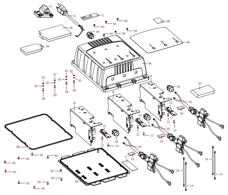
MK 106PC / MK 212PCL / MK 318PCL Charger Parts List
| Item | PART 4 | Description | Notes | Quantity |
| 2 | ✖ | DECAL-SERIAL NUMBER r NYLON | 2 | |
| 4 | ✖ | PLUG HOLDER. AC | I | |
| ✖ | MANUAL, 6/10A PCL CHARGER | 1 | ||
| 6 | ✖ | INPUT CORD. 1841% | 1 | |
| 8 | ✖ | PCB ASIA, 6A PCL CHARGER | 12/3 | |
| ✖ | PCB. 6A PCL CHARGER | 1/2/3 | ||
| ✖ | TRANSFORMER, 6A PCL CHARGE | 12/3 | ||
| ✖ | HEAT SINK. 6/10A PCL CHRGR | 1/2/3 | ||
| ✖ | INSULATOR-LG, 6/10A PCL | 12/3 | ||
| ✖ | INSULATOR-SM. 6/10A PCL | 1/2/3 | ||
| 10 | ✖ | BOARD. LED. 6/10A PCL | 12/3 | |
| 12 | ✖ | SCREW. M3. 8MM11 | 2/4/6 | |
| ✖ | LOCIOVASHER-STAR. M4 | 2/4/6 | ||
| ✖ | WASHER-3MM. ZINC-PLATED STEEL | 2/4/6 | ||
| 14 | ✖ | AC BRD CONNECT.16 AWG*117 | *MK-212PCL**MK-318PCL* | 12 |
| 16 | ✖ | AC ORO CONIIECT.16 ING.131K | ‘*MK-212PC1.* *MK-318PCL* | 1/2 |
| 18 | ✖ | STRAIN REUEE METAL PCL | 2/3/4 | |
| 20 | ✖ | OUTPUT CORD.2 CONDUCTOR. 1641VG | 1/2/3 | |
| 22 | ✖ | DECAL-BANK 1. WRAP AROUND | *MK-212PCL**MK-318Pa* | 1 |
| 24 | ✖ | DECAL-BANK 2. WRAP AROUND | *MK-212RCL”MK-318PCL* | I |
| 26 | ✖ | DECAL. BANK 3 WRAP AROUND | *MK-318PCL* | 1 |
| 28 | ✖ | SCREW- M4. 8//M. PCL CHARGER | 2/111 | |
| 30 | ✖ | WASHER-4MM. SPLIT LOCK | 2/314 | |
| 32 | ✖ | WASHER-4MM. ZP STEEL | 2/314 | |
| 34 | ✖ | LABEL-WARNING. NUT CORD | 1 | |
| 36 | ✖ | LABEL-WARNING MK-106PCL | *MK-106PCL* | I |
| ✖ | LABEL-WARNING MK-212PCL | *W-212PCL* | 1 | |
| ✖ | LABEL-WARNING MK-318PCL | *MK-318PCL* | 1 | |
| 38 | ✖ | DECAL-OVERLAY.BUT SELECT | 1 | |
| 40 | ✖ | DECAL-TOR MK-106PCL CHARGE | *MK-106PCL* | 1 |
| ✖ | DECAL-TOP. MR212PCL CHARGER | *MK-212PCL* | 1 | |
| ✖ | DECAL-TOP. MK-318PCL CHARGE | *MK-318PC1* | 1 | |
| 42 | ✖ | DECAL-ERROR CODE 6/10A PC | 1 | |
| 44 | ✖ | COVER-DIECAST. 1 BNK PCL | the-106PC1* | 1 |
| ✖ | COVER-DIECAST. 2 FMK PCI. | *MK-212PCL* | 1 | |
| ✖ | COVERDIECAST. 3 BNK PCL | *MK-318PCL* | 1 |
| 46 | ✖ | *MK-106PCL* | ||
| ✖ | BASE-DIECAST, 2 BNK PCL | *MK-212PCL* | 1 | |
| ✖ | BASE-DIECAST, 3 BNK PCL | *MK-318PCL* | 1 | |
| 48 | ✖ | GASKET, 1 BNK 6/10A PCL | *MK-106PCL* | 1 |
| ✖ | GASKET, 2 BNK 6/10A PCL | *MK-212PCL* | 1 | |
| ✖ | GASKET, 3 BNK 6/10A PCL | *MK-318PCL* | 1 | |
| 50 | ✖ | SCREW-M3 FLAT,8MM 6/10 PCL | 10/14/18 |
✖ This part is included in an assembly and cannot be ordered individually.![]() Not shown on Parts Diagram.
Not shown on Parts Diagram.
MK 110PCL / MK 220PCL / MK 330PCL / MK 440PCL / MK 550PCLMK 110PCL / MK 220PCL / MK 330PCL / MK 440PCL / MK 550PCL Charger Parts Diagram
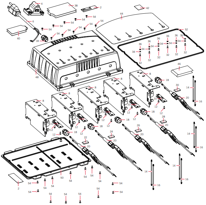
MK 110PCL / MK 220PCL / MK 330PCL / MK 440PCL / MK 550PCL Charger Parts List
| Item | Part I | Description | Notes | Quantity |
| 2 | ✖ | DECAL-SERIAL NUMBER 3″ NYLON | 2 | |
| ✖ | PLUG HOLDER. AC | |||
| ✖ | MANUAL. 6/104 PCL CHARGER | 1 | ||
| ✖ | INPUT CORD. 18AWG | 1 | ||
| 8 | ✖ | PCB AS/A. 10A PCL CHARGER | 1/2/3/4/5 | |
| ✖ | PCB. 10A PCL CHRGR | 1/2/3/4/5 | ||
| ✖ | TRANSFORMER. 10A PCL CHRGR | 1/2/3/4/5 | ||
| ✖ | HEAT SINK. 6/10A PCL CHRGR | 1/2/3/4/5 | ||
| ✖ | INSULATOR-LG. 6/10A PCL | 1/2/3/4/5 | ||
| ✖ | INSULATOR•SM. 6/104 PCL | 1/2/3/4/5 | ||
| 10 | ✖ | BOARD. LED. 6/10A PCL | 1/2/3/4/5 | |
| 12 | ✖ | SCREW. M3. 8Wil | 2/3/4/5/6 | |
| ✖ | LOCKYIASHER-STAR. M4 | 2/3/4/5/6 | ||
| ✖ | IVASHER-311151. ZINC PLATED STEEL | 2/3/4/5/6 | ||
| 14 | ✖ | AC BRD CONNECT.16 AWG.WHT | *MK-220PCL**MK-330PCL**/AK*440PCL* | 1/213/4 |
| 16 | ✖ | AC BRD CONNECT.I6 AWG.BLK | *MK-220PCL*MK-330PCL*MK*440PCL* | 1/2/3/4 |
| 18 | ✖ | STRAIN RELIEF. METAL PCL | 2/3/4/5/6 | |
| 20 | ✖ | OUTPUT CORD.2 CONDUCTOR. 16AWG | 1/2/3/4/5 | |
| 22 | ✖ | DECAL-BANK 1. WRAP AROUND | IAK-220PCL”MK-330PCL**MK-440PCL”MK-550PCL* | 1 |
| 24 | ✖ | DECAL-BANK 2. WRAP AROUND | * MK-220PCL- a MK*330F’CL**MK-440PCL”MK-550PCL * | 1 |
| 26 | ✖ | DECAL. BALK 3 WRAP AROUND | *MK-330PCL**MK-440PCL* *MK-550PCL* | 1 |
| 28 | ✖ | DECAL. BANK 4 WRAP AROUND | *MK-440PCL”MK-550PC1* | 1 |
| 30 | ✖ | DECAL BANKS WRAP AROUND | *MK-550PCL* | 1 |
| 32 | ✖ | SCREW-M4. 8MIA. PCL CHRGR | 2/3/4/5/6 | |
| 34 | ✖ | WASHER-4MM. SPLIT LOCK | 2/3/4/5/6 | |
| 36 | ✖x | WASHER-4MM. ZP STEEL | 2/314/5/6 | |
| 38 | ✖ | LABEL-WARNING MK-110PCL | *MK-110PCL* | 1 |
| ✖ | LABEL-WARNING MK-220PCL | *MK-220PCL* | 1 | |
| ✖ | LABEL-WARNING MK-330PCL | *MK-330PCL* | 1 | |
| ✖ | LABEL-WARNING MK-440PCL | *MK-440PCL* | 1 | |
| ✖ | LABEL-WARNING MK-550PCL | *MK-550PCL* | 1 | |
| ✖ | LABEL-WARNING. INPUT CORD | 1 | ||
| 42 | ✖ | DECAL-OVERLAY.BAT.SELECT |
| 44 | ✖ | DECAL-TOP, MK-110PCL CHRGR | *MK-110PCL* | 1 |
| ✖ | DECAL-TOP, MK-220PCL CHRGR | ‘MK-220PCLx | 1 | |
| ✖ | DECAL-TOP, MK-330PCL CHRGR | *MK-330PCL* | 1 | |
| ✖ | DECAL-TOP, MK-440PCL CHRGR | ‘MK-440PCLx | 1 | |
| ✖ | DECAL-TOP, MK-550PCL CHRGR | *MK-550PCL* | 1 | |
| 46 | ✖ | DECAL-ERROR CODE 6/10A PCL | 1 | |
| 48 | ✖ | COVER-DIECAST, 1 BNK PCL | *MK-110PCL* | 1 |
| ✖ | COVER-DIECAST, 2 BNK PCL | 11K-220PCLx | 1 | |
| ✖ | COVER-DIECAST, 3 BNK PCL | *MK-330PCL* | 1 | |
| ✖ | COVER-DIECAST, 4 BNK PCL | *MK-440PCL* | 1 | |
| ✖ | COVER-DIECAST, 5 BNK PCL | *MK-550PCL* | 1 | |
| 50 | ✖ | BASE-DIECAST, 1 BNK PCL | ‘MK-110PCLx | 1 |
| ✖ | BASE-DIECAST, 2 BNK PCL | *MK-220PCL* | 1 | |
| ✖ | BASE-DIECAST, 3 BNK PCL | ‘MK-330PCL* | 1 | |
| ✖ | BASE-DIECAST, 4 BNK PCL | *MK-440PCL* | 1 | |
| ✖ | BASE-DIECAST, 5 BNK PCL | ‘MK-550PCLx | 1 | |
| 52 | ✖ | GASKET, 1 BNK 6/10A PCL | *MK-110PCL* | 1 |
| ✖ | GASKET, 2 BNK 6/10A PCL | ‘MK-220PCLx | 1 | |
| ✖ | GASKET, 3 BNK 6/10A PCL | *MK-330PCL* | 1 | |
| ✖ | GASKET, 4 BNK 6/10A PCL. | ‘MK-440PCLx | 1 | |
| ✖ | GASKET, 5 BNK 6/10A PCL | *MK-550PCL* | 1 | |
| 54 | ✖ | SCREW-M3 FLAT,8MM 6/10 PCL | 10/14/18/22/24 |
✖ This part is included in an assembly and cannot be ordered individually.![]() Not shown on Parts Diagram.
Not shown on Parts Diagram.
RECOMMENDED ACCESSORIES
CHARGER OUTPUT EXTENSION CABLESExtension cables are ideal when standard charger cables will not reach bow, center, or transom battery compartments. Features WAGO® Wall-Nut™ quick connectors (UL Listed).Fused (30 amp) positive and negative leads. Available in 15’ length.
AC POWER PORT(Freshwater & Saltwater)Our convenient adapter allows quick thru-hull connection to an AC extension cord using the male AC plug from any of our chargers. No cutting or splicing required. The watertight cover and gasket prevent corrosion on the AC plug when it isn’t in use.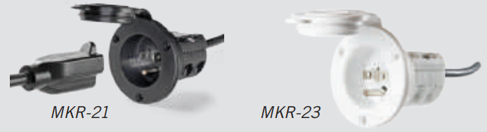
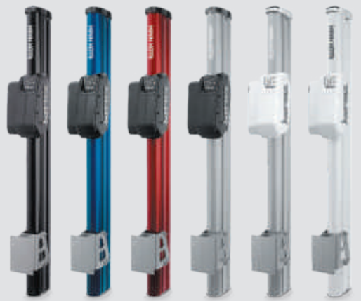
TALON SHALLOW WATER ANCHORIntroducing the all-new, sleek redesigned Talon. Talon is the only shallow water anchor with up to 15’ of anchoring depth, multiple anchoring modes, and control from the bow, transom, console, remote or mobile device.
 BUILT-IN WORK LIGHTLet’s you tie lines and work from the transom any time of day — or night. Includes both white and blue LED lights with three brightness settings.
 BLUETOOTH® CONNECTIVITYLet’s you control Talon from your mobile device and easily update it. Also opens up communication to other control options.
 UP TO 15’ DEEPControl more water and catch more fish with the first 15’ shallow water anchor.
 MORE CONTROL OPTIONS
- Control Panel
- Wireless Remote
- Mobile App
- Wireless Foot Switch
- Humminbird® Connectivity
- i-Pilot® &i-Pilot Link TM Remote
MINN KOTA ACCESSORIESWe offer a wide variety of trolling motor accessories, including: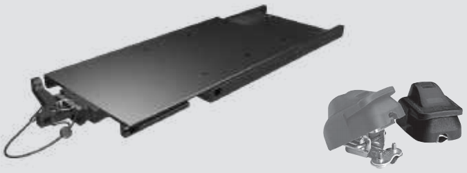
| • 60-Amp Circuit Breaker• Mounting Brackets• Stabilizer Kits• Extension Handles | • Battery Connectors• Battery Boxes• Quick Connect Plugs |
![]()
 minnkotamotors.comPart #2367135
Minn Kota Consumer & Technical Service Johnson Outdoors Marine Electronics, Inc.PO Box 8129Mankato, MN 56001121 Power DriveMankato, MN 56001Phone (800) 227-6433Fax (800) 527-4464
 ©2021 Johnson Outdoors Marine Electronics, Inc.All rights reserved.
References
[xyz-ips snippet=”download-snippet”]