![]()
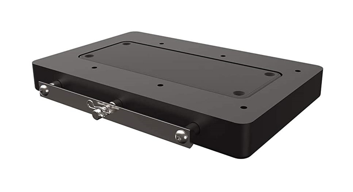
MKA-53/RTA-54 ELECTRIC STEERCOMPOSITE RELEASE BRACKET1854053 & 1854054
The MKA-53 is recommended with the Ulterra™, Terrova®, PowerDrive™, PowerDrive V2, and the Pontoon PowerDrive™ Minn Kota® Motors and the Deckhand 40. The RTA-54 is recommended with the RT Ulterra™, RT Terrova ®, RT PowerDrive™ and RT PowerDrive V2 Minn Kota ® Motors.
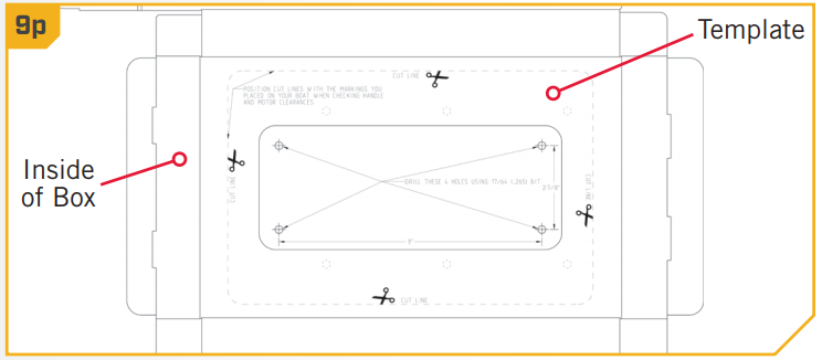
NOTICE: Images are a graphical representation and may vary from your motor. Save the box! A template for installation is printed on the inside of the box.
| Item /Assembly | Part # | Description | Qty. |
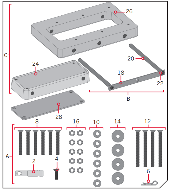
| AItems 2-16 | 2994935 | BAG ASM, HT COMP ORB | 1 |
| 2 | 2372633 | PIN-PADLOCK MAX/AT QCK REL. | 1 |
| 4 | 2373484 | SCREW-1/4-20 X 7/8 PFH SS | 1 |
| 6 | 2260800 | CLIP-HAIR SPRING,SS,MAX BG | 1 |
| 8 | 2223446 | SCREW-1/4-20 X 2″ PFH SS | 6 |
| 10 | 2371712 | WASHER-FLAT 9/32 X 5/8 X 1/16 | 6 |
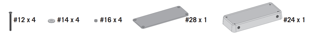
| 12 | 2373482 | SCREW-1/4-20 X 3′ PFH SS | 4 |
| 14 | 2261713 | WASHER-1/4 FLAT 18-8 SS | 4 |
| 16 | 2073100 | NUT-HEX 1/4-20 NYLOC-1AM SS | 10 |
| BItems 18-22 | 2990955 | HANDLE ASM, HT COMP ORB | 1 |
| 18 | x | HANDLE, SS, HT COMP ORB | 1 |
| 20 | x | PIN-LOCKING, SS, HTC QRB | 2 |
| 22 | x | SCREW-5/16-18 X 3/4 BHCS SS | 2 |
| CItems 24-26 | 2991690 | PLATE ASM, BLACK, HTC QRB | 1 |
| 2991691 | PLATE ASM, WHITE, HTC ORB | 1 | |
| 24 | 2371690 | PLATE-INNER, BLACK, HTC QRB | 1 |
| 2371691 | PLATE-INNER. WHITE, HTC ORB | 1 | |
| 26 | 2371692 | PLATE-OUTER, BLACK, HTC QRB | 1 |
| 2371693 | PLATE-OUTER, WHITE, HTC QRB | 1 | |
| 28 | 2378848 | STIFFENER-PLATE/PUCK,BLK | 1 |
| 2378849 | STIFFENER-PLATERUCK,WHT | 1 | |
| • | 2374951 | INSTRC. HT COMPOSITE QRB | 1 |
Not shown on Parts Diagram.✖ This part is included in an assembly and cannot be ordered individually.
TOOLS AND RESOURCES REQUIRED
- #3 Phillips Screw Driver
- Scissors
- 7/16” Box End Wrench
- A second person to help
- Drill
- 17/64” Drill Bit
- 33/64 (.516”) Drill Bitwith the installation
MOUNTING CONSIDERATIONS
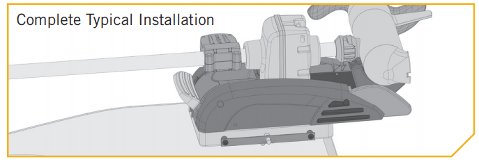
It is recommended that the motor be mounted as close to the centerline of the boat as possible. The motor must not encounter any obstructions as it is lowered into the water or raised into the boat when stowed and deployed. Make sure the motor rest is positioned far enough beyond the edge of the boat. Make sure the area under the mounting location is flat, clear to drill holes and install nuts and washers.
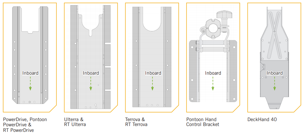
The MKA-53 and RTA-54 are designed to be compatible with the Ulterra™, RT Ulterra™, Terrova®, RT Terrova ® , PowerDrive™, RT PowerDrive™, PowerDrive V2 and RT PowerDrive V2 and the Pontoon PowerDrive™ Minn Kota ® motors and the Deckhand 40. The base extrusion or mounting bracket of the trolling motors may vary. Please note the appearance of the applicable trolling motors and mounting brackets. For a complete list of motors compatible with the MKA-53 and RTA-54, please refer to the website at minnkotamotors.com.
INSTALLATION
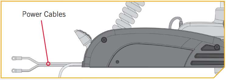
- a. Make sure that the Power Cables from the battery are disconnected, or that the breaker, if equipped, is “off”.

- b. Place the mount on an elevated, level surface such as a workbench or the tailgate of a pickup. The motor should be in the stowed position.c. Remove the four side plate screws using a #3 Phillips screwdriver. Two of these screws will be located on each side of the mount.NOTICE: If mounting to a Pontoon Hand Control Bracket or Deckhand 40, directions specific to motor installation do not apply.NOTICE: This motor weighs up to 65lbs. We recommend having a second person help with the installation.
- d. Remove the Right Sideplate.e. Swing the Left Sideplate out and away from the Base Extrusion. Removing the sideplates exposes the Mounting Holes in the Base Extrusion.
- ITEM(S) NEEDEDf. The Plate Assembly (Item #C) consists of the Outer Plate (Item #26) and the Inner Plate (Item #24). Take the Outer Plate and align the Mounting Holes with the Mounting Holes in the Base Extrusion.The appearance of your Base Extrusion may vary depending on motor type. The Outer Plate will be oriented so that the end with the screw holes farthest from the edge sits under the Power Cord when mounted to the motor. There is a single screw hole on each side of the Outer Plate that does not pass all the way through the plate. The screw hole will be used to hold the Padlock Pin in place later in the installation. Turn the Outer Plate so this screw-hole is facing downwards.g. Use six each of the 1/4-20 X 2″ Flat Head Screw (Item #8), 9/32 X 5/8 X 1/16 Flat Washer (Item #10), and Nylock Nuts (item #16) to secure the Outer Plate to the Base Extrusion. The screws will pass from the bottom up, through the Outer Plate, and then the Base Extrusion. The Nylock Nuts are placed on the screws on top of the Base Extrusion and tightened with the 7/16” Box End Wrench. Make sure all hardware is secure.NOTICE: If you are mounting an Ulterra to the Quick Release Bracket, the Clipped Washers that were previously used to install the motor to the boat, or included in the mounting hardware that came with the Ulterra motor should be used. Place the Clipped Washer above the Base Extrusion, between the Base Extrusion and the Nylock Nut. Refer to the Ulterra Owner’s Manual online at minnkotamotors.com for complete details on mounting the Ulterra. To prevent seizing of the stainless steel hardware, do not use high-speed installation tools. Wetting the screws or applying an anti-seize may help prevent seizing.
- h. Replace the Right Sideplate.i. Swing the Left Sideplate back into its correct position on the Base Extrusion.j. Replace the four side plate screws using a #3 Phillips screwdriver. Two of these screws will be located on each side of the mount.
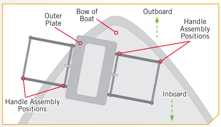
- ITEM(S) NEEDEDk. Determine if the motor will be mounted on the Port or Starboard side of the bow and if the Handle Assembly (Item #B) will release the inboard or outboard. Be sure that the Handle Assembly will not encounter any obstructions on the bow of the boat and can be completely pulled out to release the plates when mounted. The bracket is designed so that the handle can be positioned on either side to accommodate clearances and personal preferences. The side of the bracket that the Handle Assembly isused on will determine which side the Padlock Pin (Item #2) will be installed on.NOTICE: Make sure that the motor will not encounter any obstructions when positioning the motor on and offthe composite bracket. The exact placement of the motor and bracket, when mounting, may vary depending on the boat, boat deck, and which base extrusion or bracket the bracket is being mounted to. The Ulterra motor cannot be deployed before mounting and connecting a power source.
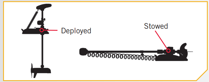
- l. Place the Quick Release Bracket and motor as close to the centerline or keel of the boat as possible. Make sure to check clearance of the motor, bracket and handle for any possible obstructions on the bow of the boat.m. Check placement with the motor in the stowed and deployed positions. Review the mounting considerations at the beginning of the installation.When the motor is in the deployed position, make sure that the Shaft is 1-1/2” out past the Gunwale of the boat. The lower unit, when stowed and deployed must not encounter any obstructions.n. Mark the side and rear edges of the Outer Plate on the bow of the boat. These markings will be used to position a template that will be used to mark and drill the holes for the Inner Plate.NOTICE: The Ulterra motor cannot be deployed before mounting and connecting a power source.
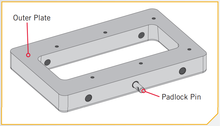
- ITEM(S) NEEDEDo. Once an orientation for the Handle Assembly is selected place the Padlock Pin into the Outer Plate on that side, so that the larger diameter of the pin is in the Outer Plate. Rotate the Pin so that the hole in the pin lines up with the hole in the Outer Plate.Secure the Pin with the 1/4-20 X 7/8 Screw (Item #4) using an #3 Screwdriver.
- p. Take the box that the Quick Release Bracket came in and carefully pull the glued edges apart and open the box so that it lays flat. On the inside of the box, a template is printed to help locate, mark, and drill the holes for the Inner Plate. Cut the template out and place it on the bow. Align it with the markings that were made while checking handle and motor clearances. Make sure that the orientation of the Outer Plate in the template matches the orientation of the Outer Plate as it is attached to the Motor.q. The template indicates 4 drill holes on the Inner Plate. Use the template to mark the locations of the drill holes, then use a 17/64″ drill bit to drill the holes.
- ITEM(S) NEEDEDr. Set the template aside and take the Stiffener Plate (Item #28) and place it on top of the Inner Plate (Item#24). One surface of the Inner Plate is recessed to accommodate the placement of the Stiffener Plate. This surface should face upward. The Stiffener plate should be set on the Inner Plates the recesses for the flat head screws in each corner are facing upwards.s. Place the Inner Plate and Stiffener Plate on the bow of the boat and align them with the holes that were drilled using the template as a guide. For the best fit, it is recommended that the mounting surface under the Inner Plate is completely flat. Use shims or rubber washers to level the mounting surface.If the Inner Plate is not mounted flat, the Handle Assembly will not slide properly.t. Put a 1/4-20 X 3” Flat Head Screw (Item #12) in each of the four drilled locations. The Flat Head The screw should pass through the Stiffener Plate and Inner Plate and then the boat deck.u. Place a Flat Washer (Item #14) and then a Nylock Nut (Item #16) at the end of each bolt as shown and tightened with the 7/16” Box End Wrench. Make sure all hardware is secure.
- v. Place the outer plate attached to the motor back onto the inner plate that is mounted to the bow of the boat and secure with the handle assembly and clip spring. Always make sure that the handle is fully inserted and retained using the hair clip pin. If the Handle Assembly does not slide easily into place, it may be necessary to ream out the handle rod holes. With the Inner and Outer Plate assembled, use a 33/64 (.516”) Drill Bit to ream the rod holes so that the Handle Assembly slides easily into place.w. You can use a padlock in place of the Hair Clip Pin to prevent motor theft.NOTICE: Lock your motor to help prevent theft.
 c. Remove the four side plate screws using a #3 Phillips screwdriver. Two of these screws will be located on each side of the mount.NOTICE: If mounting to a Pontoon Hand Control Bracket or Deckhand 40, directions specific to motor installation do not apply.
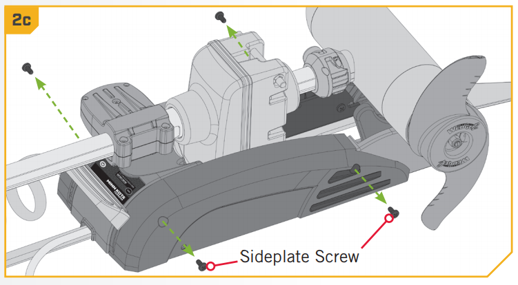 NOTICE: This motor weighs up to 65lbs. We recommend having a second person help with the installation.
 e. Swing the Left Sideplate out and away from the Base Extrusion. Removing the sideplates exposes the Mounting Holes in the Base Extrusion.
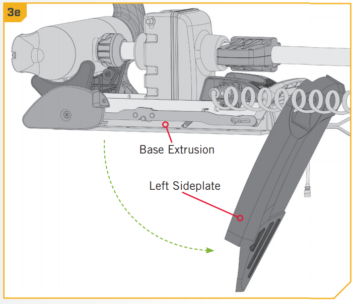
 f. The Plate Assembly (Item #C) consists of the Outer Plate (Item #26) and the Inner Plate (Item #24). Take the Outer Plate and align the Mounting Holes with the Mounting Holes in the Base Extrusion.The appearance of your Base Extrusion may vary depending on motor type. The Outer Plate will be oriented so that the end with the screw holes farthest from the edge sits under the Power Cord when mounted to the motor. There is a single screw hole on each side of the Outer Plate that does not pass all the way through the plate. The screw hole will be used to hold the Padlock Pin in place later in the installation. Turn the Outer Plate so this screw-hole is facing downwards.
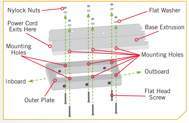 g. Use six each of the 1/4-20 X 2″ Flat Head Screw (Item #8), 9/32 X 5/8 X 1/16 Flat Washer (Item #10), and Nylock Nuts (item #16) to secure the Outer Plate to the Base Extrusion. The screws will pass from the bottom up, through the Outer Plate, and then the Base Extrusion. The Nylock Nuts are placed on the screws on top of the Base Extrusion and tightened with the 7/16” Box End Wrench. Make sure all hardware is secure.NOTICE: If you are mounting an Ulterra to the Quick Release Bracket, the Clipped Washers that were previously used to install the motor to the boat, or included in the mounting hardware that came with the Ulterra motor should be used. Place the Clipped Washer above the Base Extrusion, between the Base Extrusion and the Nylock Nut. Refer to the Ulterra Owner’s Manual online at minnkotamotors.com for complete details on mounting the Ulterra. To prevent seizing of the stainless steel hardware, do not use high-speed installation tools. Wetting the screws or applying an anti-seize may help prevent seizing.
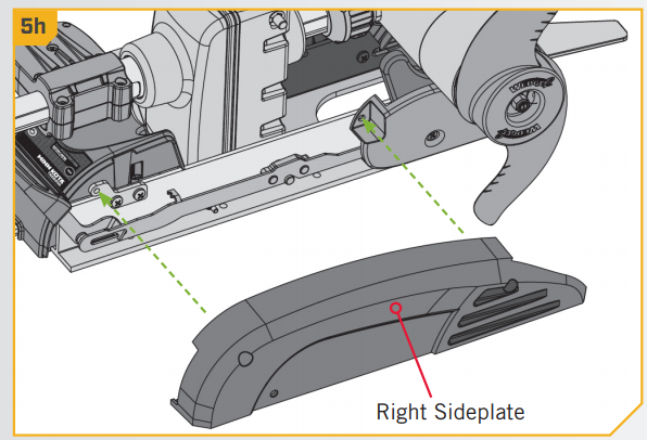 i. Swing the Left Sideplate back into its correct position on the Base Extrusion.
 j. Replace the four side plate screws using a #3 Phillips screwdriver. Two of these screws will be located on each side of the mount.
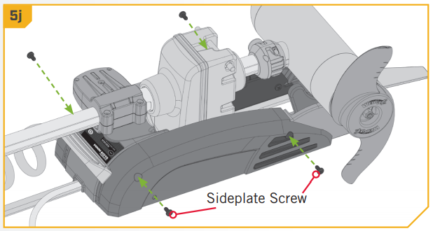
 k. Determine if the motor will be mounted on the Port or Starboard side of the bow and if the Handle Assembly (Item #B) will release the inboard or outboard. Be sure that the Handle Assembly will not encounter any obstructions on the bow of the boat and can be completely pulled out to release the plates when mounted. The bracket is designed so that the handle can be positioned on either side to accommodate clearances and personal preferences. The side of the bracket that the Handle Assembly isused on will determine which side the Padlock Pin (Item #2) will be installed on.
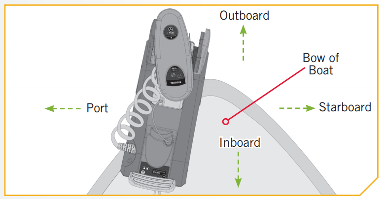
 NOTICE: Make sure that the motor will not encounter any obstructions when positioning the motor on and offthe composite bracket. The exact placement of the motor and bracket, when mounting, may vary depending on the boat, boat deck, and which base extrusion or bracket the bracket is being mounted to. The Ulterra motor cannot be deployed before mounting and connecting a power source.
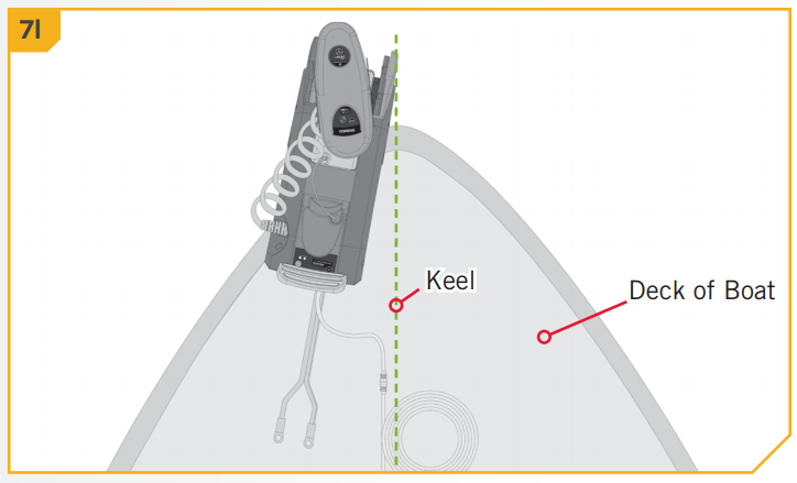 m. Check placement with the motor in the stowed and deployed positions. Review the mounting considerations at the beginning of the installation.When the motor is in the deployed position, make sure that the Shaft is 1-1/2” out past the Gunwale of the boat. The lower unit, when stowed and deployed must not encounter any obstructions.
 n. Mark the side and rear edges of the Outer Plate on the bow of the boat. These markings will be used to position a template that will be used to mark and drill the holes for the Inner Plate.
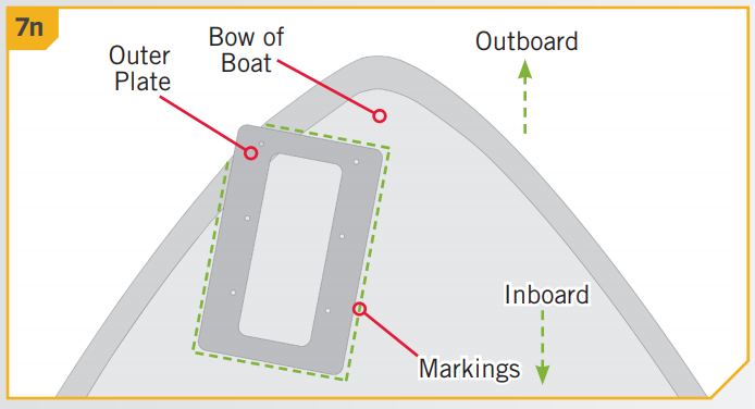 NOTICE: The Ulterra motor cannot be deployed before mounting and connecting a power source.
 o. Once an orientation for the Handle Assembly is selected place the Padlock Pin into the Outer Plate on that side, so that the larger diameter of the pin is in the Outer Plate. Rotate the Pin so that the hole in the pin lines up with the hole in the Outer Plate.Secure the Pin with the 1/4-20 X 7/8 Screw (Item #4) using an #3 Screwdriver.
 q. The template indicates 4 drill holes on the Inner Plate. Use the template to mark the locations of the drill holes, then use a 17/64″ drill bit to drill the holes.
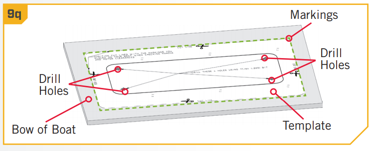
 r. Set the template aside and take the Stiffener Plate (Item #28) and place it on top of the Inner Plate (Item#24). One surface of the Inner Plate is recessed to accommodate the placement of the Stiffener Plate. This surface should face upward. The Stiffener plate should be set on the Inner Plates the recesses for the flat head screws in each corner are facing upwards.
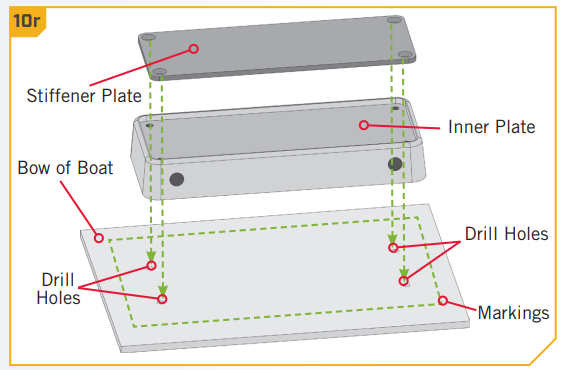 s. Place the Inner Plate and Stiffener Plate on the bow of the boat and align them with the holes that were drilled using the template as a guide. For the best fit, it is recommended that the mounting surface under the Inner Plate is completely flat. Use shims or rubber washers to level the mounting surface.If the Inner Plate is not mounted flat, the Handle Assembly will not slide properly.t. Put a 1/4-20 X 3” Flat Head Screw (Item #12) in each of the four drilled locations. The Flat Head The screw should pass through the Stiffener Plate and Inner Plate and then the boat deck.
 u. Place a Flat Washer (Item #14) and then a Nylock Nut (Item #16) at the end of each bolt as shown and tightened with the 7/16” Box End Wrench. Make sure all hardware is secure.
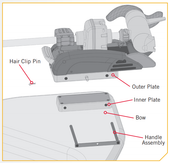 w. You can use a padlock in place of the Hair Clip Pin to prevent motor theft.NOTICE: Lock your motor to help prevent theft.
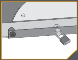
For warranty information, please visit minnkotamotors.com.
![]()
Minn Kota Consumer & Technical ServiceJohnson Outdoors Marine Electronics, Inc.PO Box 8129Mankato, MN 56001
121 Power DriveMankato, MN 56001Phone (800) 227-6433Fax (800) 527-4464

©2021 Johnson Outdoors Marine Electronics, Inc.All rights reserved.
Part #2374951ECN 42093Rev D06/21
References
[xyz-ips snippet=”download-snippet”]