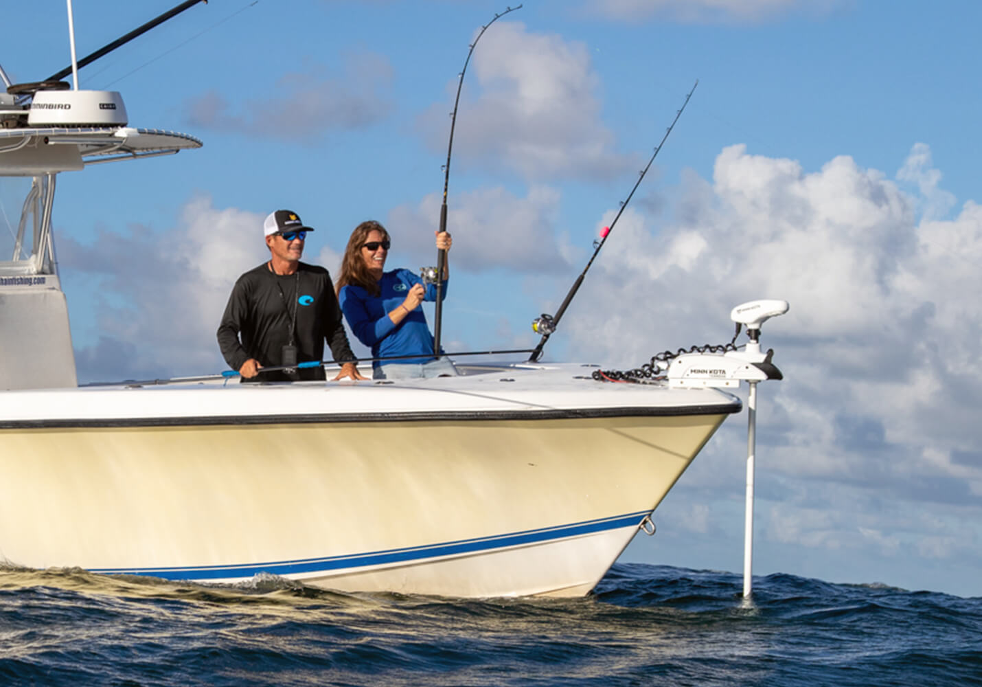
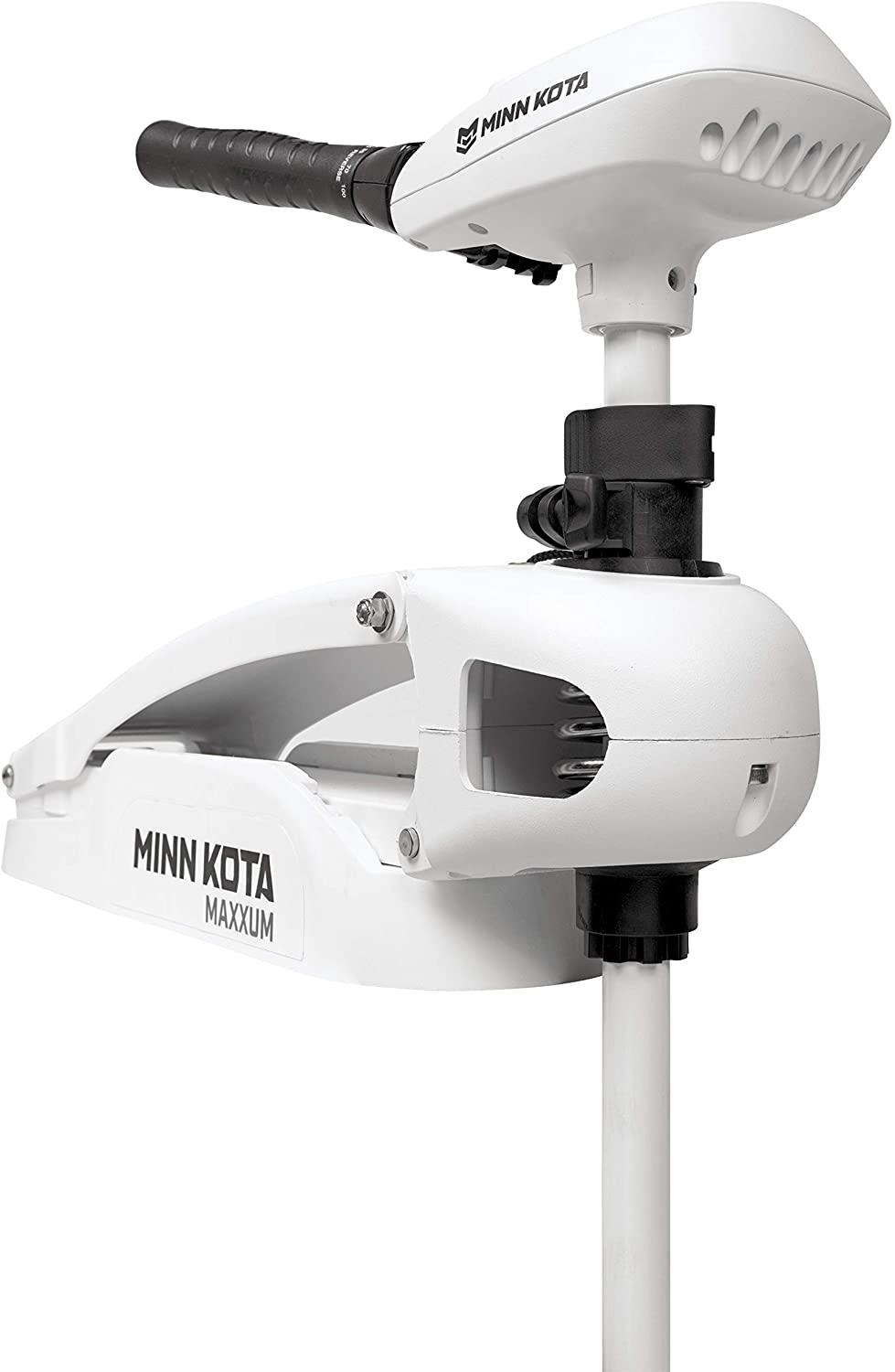
MINN KOTA Riptide Edge Bow-Mount Trolling Motor
INTRODUCTION
THANK YOUThank you for choosing Minn Kota. We believe that you should spend more time fishing and less time positioning your boat. That’s why we build the smartest, toughest, most intuitive trolling motors on the water. Every aspect of a Minn Kota trolling motor is thought out and rethought until it’s good enough to bear our name. Countless hours of research and testing provide you the Minn Kota advantage that can truly take you “Anywhere. Anytime.” We don’t believe in shortcuts. We are Minn Kota. And we are never done helping you catch more fish.
REGISTRATIONRemember to keep your receipt and immediately register your trolling motor. A registration card is included with your motor or you can complete registration on our website at minnkotamotors.com
SERIAL NUMBERYour Minn Kota 11-character serial number is very important. It helps to determine the specific model and year of manufacture. When contacting Consumer Service or registering your product, you will need to know your product’s serial number. We recommend that you write the serial number down so that you have it available for future reference.
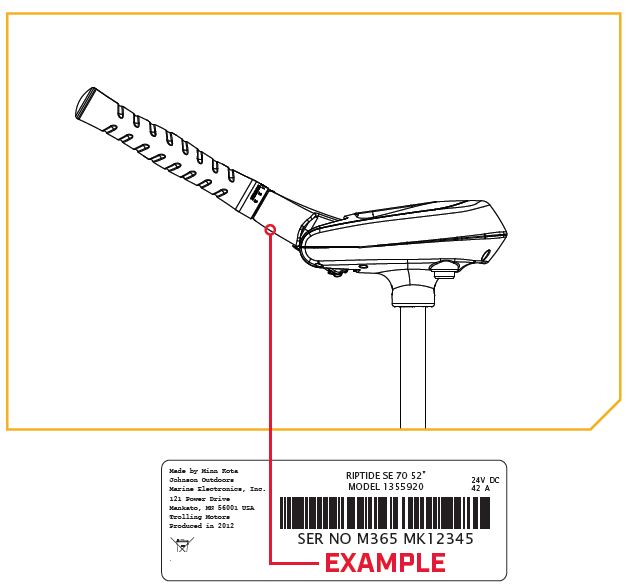
NOTICE: The serial number on your Riptide Edge is located underneath the tiller handle.
SAFETY CONSIDERATIONS
Please thoroughly read the user manual. Follow all instructions and heed all safety and cautionary notices. Use of this motor is only permitted for persons that have read and understood these user instructions. Minors may use this motor only under adult supervision.
WARNING:
- You are responsible for the safe and prudent operation of your vessel. We have designed your Minn Kota product to be an accurate and reliable tool that will enhance boat operation and improve your ability to catch fish. This product does not relieve you from the responsibility for safe operation of your boat. You must avoid hazards to navigation and always maintain a permanent watch so you can respond to situations as they develop. You must always be prepared to regain manual control of your boat. Learn to operate your Minn Kota product in an area free from hazards and obstacles.
- Never run the motor out of the water, as this may result in injuries from the rotating propeller. The motor should be disconnected from the power source when it is not in use or is off the water. When connecting the power-supply cables of the motor to the battery, ensure that they are not kinked or subject to chafe and route them in such a way that persons cannot trip over them. Before using the motor make sure that the insulation of the power cables is not damaged. Disregarding these safety precautions may result in electric shorts of battery(s) and/or motor. Always disconnect motor from battery(s) before cleaning or checking the propeller. Avoid submerging the complete motor as water may enter the lower unit through control head and shaft. If the motor is used while water is present in the lower unit considerable damage to the motor can occur. This damage will not be covered by warranty.
- Take care that neither you nor other persons approach the turning propeller too closely, neither with body parts nor with objects.The motor is powerful and may endanger or injure you or others. While the motor is running watch out for persons swimming and for floating objects. Persons who lack the ability to run the motor or whose reactions are impaired by alcohol, drugs, medication, or other substances are not permitted to use this motor. This motor is not suitable for use in strong currents. The constant noise pressure level of the motor during use is less than 70dB(A). The overall vibration level does not exceed 2,5 m/sec2.
- When stowing or deploying the motor, keep fingers clear of all hinge and pivot points and all moving parts. In the event of unexpected operation, remove power leads from the battery.
- It is recommended to only use Johnson Outdoors approved accessories with your Minn Kota motor. Using non-approved accessories including to mount or control your motor may cause damage, unexpected motor operation and injury. Be sure to use the product and approved accessories, including remotes, safely and in the manner directed to avoid accidental or unexpected motor operation. Keep all factory installed parts in place including motor and accessory covers, enclosures and guards.
WARRANTY
WARRANTY ON MINN KOTA SALTWATER TROLLING MOTORSJohnson Outdoors Marine Electronics, Inc. (“JOME”) extends the following limited warranty to the original retail purchaser only. Warranty coverage is not transferable.
Minn Kota Limited Two-Year Warranty on the Entire ProductJOME warrants to the original retail purchaser only that the purchaser’s new Minn Kota saltwater trolling motor will be materially free from defects in materials and workmanship appearing within two (2) years after the date of purchase. JOME will (at its option) either repair or replace, free of charge, any parts found by JOME to be defective during the term of this warranty. Such repair, or replacement shall be the sole and exclusive liability of JOME and the sole and exclusive remedy of the purchaser for breach of this warranty.
Minn Kota Limited Lifetime Warranty on Composite ShaftJOME warrants to the original retail purchaser only that the composite shaft of the purchaser’s Minn Kota trolling motor will be materially free from defects in materials and workmanship appearing within the original purchaser’s lifetime. JOME will provide a new composite shaft, free of charge, to replace any composite shaft found by JOME to be defective during the term of this warranty. Providing a new composite shaft shall be the sole and exclusive liability of JOME and the sole and exclusive remedy of the purchaser for breach of this warranty; and purchaser shall be responsible for installing, or for the cost of labor to install, any new composite shaft provided by JOME.
Exclusions & LimitationsThis limited warranty does not apply to products that have been used commercially or for rental purposes. This limited warranty does not cover normal wear and tear, blemishes that do not affect the operation of the product, or damage caused by accidents, abuse, alteration, modifi cation, shipping damages, negligence of the user or misuse, improper or insuffi cient care or maintenance. DAMAGE CAUSED BY THE USE OF OTHER REPLACEMENT PARTS NOT MEETING THE DESIGN SPECIFICATIONS OF THE ORIGINAL PARTS WILL NOT BE COVERED BY THIS LIMITED WARRANTY. The cost of normal maintenance or replacement parts which are not in breach of the limited warranty are the responsibility of the purchaser. Prior to using products, the purchaser shall determine the suitability of the products for the intended use and assumes all related risk and liability. Any assistance JOME provides to or procures for the purchaser outside the terms, limitations or exclusions of this limited warranty will not constitute a waiver of the terms, limitations or exclusions, nor will such assistance extend or revive the warranty. JOME will not reimburse the purchaser for any expenses incurred by the purchaser in repairing, correcting or replacing any defective products or parts, except those incurred with JOME’s prior written permission. JOME’S AGGREGATE LIABILITY WITH RESPECT TO COVERED PRODUCTS IS LIMITED TO AN AMOUNT EQUAL TO THE PURCHASER’S ORIGINAL PURCHASE PRICE PAID FOR SUCH PRODUCT.
Minn Kota Service InformationTo obtain warranty service in the U.S., the product believed to be defective, and proof of original purchase (including the date of purchase), must be presented to a Minn Kota Authorized Service Center or to Minn Kota’s factory service center in Mankato, MN. Any charges incurred for service calls, transportation or shipping/freight to/from the Minn Kota Authorized Service Center or factory, labor to haul out, remove, re-install or re-rig products removed for warranty service, or any other similar items are the sole and exclusive responsibility of the purchaser. Products purchased outside of the U.S. must be returned prepaid with proof of purchase (including the date of purchase and serial number) to any Authorized Minn Kota Service Center in the country of purchase. Warranty service can be arranged by contacting a Minn Kota Authorized Service Center or by contacting the factory at 1-800-227-6433 or email Products repaired or replaced will be warranted for the remainder of the original warranty period [or for 90 days from the date of repair or replacement, whichever is longer]. For any product that is returned for warranty service that JOME finds to be not covered by or not in breach of this limited warranty, there will be a billing for services rendered at the prevailing posted labor rate and for a minimum of at least one hour.
NOTICE: Do not return your Minn Kota product to your retailer. Your retailer is not authorized to repair or replace products.NOTICE: THERE ARE NO EXPRESS WARRANTIES OTHER THAN THESE LIMITED WARRANTIES. IN NO EVENT SHALL ANY IMPLIED WARRANTIES INCLUDING ANY IMPLIED WARRANTIES OF MERCHANTABILITY OR FITNESS FOR PARTICULAR PURPOSE, EXTEND BEYOND THE DURATION OF THE RELEVANT EXPRESS LIMITED WARRANTY. IN NO EVENT SHALL JOME BE LIABLE FOR PUNITIVE, INDIRECT, INCIDENTAL, CONSEQUENTIAL OR SPECIAL DAMAGES. Without limiting the foregoing, JOME assumes no responsibility for loss of use of product, loss of time, inconvenience or other damage.
Some states do not allow limitations on how long an implied warranty lasts or the exclusion or limitation of incidental or consequential damages, so the above limitations and/or exclusions may not apply to you. This warranty gives you specific legal rights and you may also have other legal rights which vary from state to state.
KNOW YOUR BOAT

FEATURES
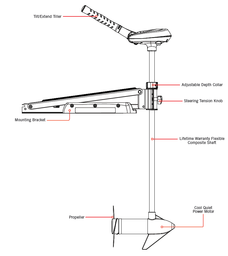
NOTICE: Specifications subject to change without notice. This diagram is for reference only and may differ from your actual motor.
INSTALLATION
MOUNTING CONSIDERATIONS
Please review the following guidelines before beginning the installation of the Riptide Edge:NOTICE: We recommend that you have another person help with this installation.
- The Motor should be mounted as close to the centerline or keel of the boat as possible when it is deployed.
- Make sure bow area under the chosen location is clear and unobstructed for drilling.
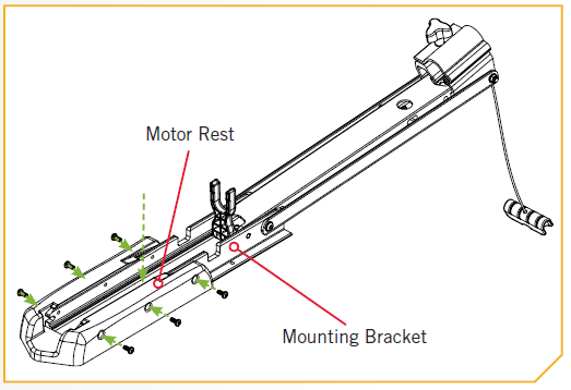
- Make sure the Motor Rest is positioned far enough beyond the edge of the boat. The Motor, as it is lowered into the water or raised into the boat, must not encounter any obstructions.
TOOLS AND RESOURCES REQUIRED
- Phillips Screw Driver
- Drill
- 9/32” Drill Bit
- 7/16” Box End Wrench
- A second person to help with the installation
MOUNT INSTALLATION
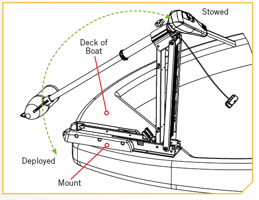
- Review the mounting considerations at the beginning of this section. Place the Mount as close to the centerline or keel of the boat as possible, with the motor in the deployed position, on the deck of the boat. Check placement with the motor in the stowed and deployed positions.
 WARNING:
- When raising or lowering motor, keep fingers clear of all hinge and pivot points and all moving parts.
- Make sure the motor is mounted on a level surface and is not connected to a power source.
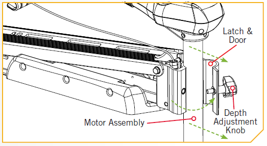
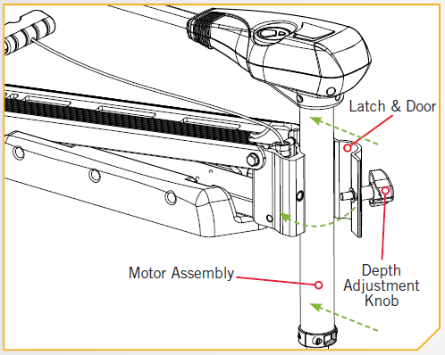
- Deploy the motor and remove the Motor Assembly from the Mount by loosening the Depth Adjustment Knob and opening the Latch & Door.
- Position the Mount again in the stowed position.
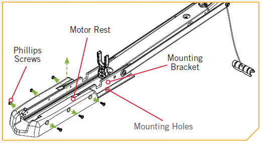
- Temporarily remove the six Phillips Screws that fasten the Motor Rest to the Mounting Bracket and remove the Motor Rest to expose the motor mounting hole pattern.
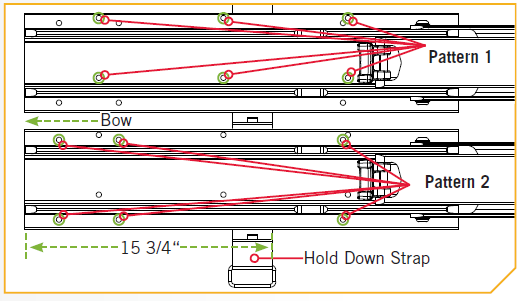
- Determine the mounting hole pattern you wish to use. Using the mounting holes in the mount as your template, mark the top deck of the boat with a pencil or similar marking tool.
- Remove the Mount from the deck of the boat and drill the holes that you marked in the previous step using a 9/32” Drill Bit and Drill. Be careful not to damage any wiring or critical features that may exist under the surface you are drilling through.
- Place the Mount on the deck of the boat again and verify the Hold Down Strap is positioned 15 ¾” from the front of the bow mount.
- Fasten the mount to the deck of the boat using the supplied 1/4” – 20 X 2” bolts, washers and nuts. Tighten the stainless steel hardware securely but slowly to the deck of the boat using a 7/16” box end wrench.NOTICE: To prevent seizing of the stainless steel hardware, do not use high speed installation tools. Wetting the screws or applying an anti-seize may help prevent seizing.

 WARNING:
 NOTICE: To prevent seizing of the stainless steel hardware, do not use high speed installation tools. Wetting the screws or applying an anti-seize may help prevent seizing.
Installation
- Reinstall the Motor Rest using the six original 1/4” Phillips Screws.
- Reinstall the Motor Assembly into the Mount and securely tighten the Depth Adjustment Knob.
Battery Wiring & Installation
BOAT RIGGING & PRODUCT INSTALLATIONFor safety and compliance reasons, we recommend that you follow American Boat and Yacht Council (ABYC) standards when rigging your boat. Altering boat wiring should be completed by a qualified marine technician. The following specifications are for general guidelines only:
CAUTION:
- These guidelines apply to general rigging to support your Minn Kota motor. Powering multiple motors or additional electrical devices from the same power circuit may impact the recommended conductor gauge and circuit breaker size. If you are using wire longer than that provided with your unit, follow the conductor gauge and circuit breaker sizing table below. If your wire extension length is more than 25 feet, we recommend that you contact a qualified marine technician.
- An over-current protection device (circuit breaker or fuse) must be used. Coast Guard requirements dictate that each ungrounded current-carrying conductor must be protected by a manually reset, trip-free circuit breaker or fuse. The type (voltage and current rating) of the fuse or circuit breaker must be sized accordingly to the trolling motor used. The table below gives recommended guidelines for circuit breaker sizing.
CONDUCTOR GAUGE AND CIRCUIT BREAKER SIZING TABLE
This conductor and circuit breaker sizing table is only valid for the following assumptions:
- No more than 2 conductors are bundled together inside of a sheath or conduit outside of engine spaces.
- Each conductor has 105° C temp rated insulation.
- No more than 5% voltage drop allowed at full motor power based on published product power requirements.
|
Motor Thrust / Model |
Max Amp Draw |
Circuit Breaker |
Wire Extension Length | ||||
| 5 feet | 10 feet | 15 feet | 20 feet | 25 feet | |||
| 30 lb. | 30 |
50 Amp @ 12 VDC |
10 AWG | 10 AWG | 8 AWG | 6 AWG | 4 AWG |
| 40 lb., 45 lb. | 42 | 10 AWG | 8 AWG | 6 AWG | 4 AWG | 4 AWG | |
| 50 lb., 55 lb. | 50 | 60 Amp @ 12 VDC | 8 AWG | 6 AWG | 4 AWG | 4 AWG | 2 AWG |
| 70 lb. | 42 | 50 Amp @ 24 VDC | 10 AWG | 10 AWG | 8 AWG | 8 AWG | 6 AWG |
| 80 lb. | 56 | 60 Amp @ 24 VDC | 8 AWG | 8 AWG | 8 AWG | 6 AWG | 6 AWG |
| 101 lb. | 46 | 50 Amp @ 36 VDC | 8 AWG | 8 AWG | 8 AWG | 8 AWG | 8 AWG |
| Engine Mount 101 | 50 | 60 Amp @ 36 VDC | 8 AWG | 8 AWG | 8 AWG | 8 AWG | 8 AWG |
| 112 lb. | 52 | 60 Amp @ 36 VDC | 8 AWG | 8 AWG | 8 AWG | 8 AWG | 8 AWG |
| Engine Mount 160 | 116 | (2) x 60 Amp @ 24 VDC | 6 AWG | 6 AWG | 4 AWG | 2 AWG | 2 AWG |
| E-Drive | 40 | 50 Amp @ 48 VDC | 10 AWG | 10 AWG | 10 AWG | 10 AWG | 10 AWG |
NOTICE: Wire Extension Length refers to the distance from the batteries to the trolling motor leads. Consult website for available thrust options. Maximum Amp Draw values only occur intermittently during select conditions and should not be used as continuous amp load ratings.
SELECTING THE CORRECT BATTERIES
The motor will operate with any lead acid, deep cycle marine 12-volt battery/batteries. For best results, use a deep cycle, marine battery with at least a 105 amp-hour rating. Maintain battery at full charge. Proper care will ensure having battery power when you need it, and will significantly improve the battery life. Failure to recharge lead-acid batteries (within 12-24 hours) is the leading cause of premature battery failure. Use a multi-stage charger to avoid overcharging. We offer a wide selection of chargers to fit your charging needs. If you are using a crank battery to start a gasoline outboard, we recommend that you use a separate deep cycle marine battery/batteries for your Minn Kota trolling motor. For more information on battery selection and rigging, please visit minnkotamotors.com. Minn Kota trolling motors can run on Lithium Ion batteries. However, they are specifically designed to run on traditional lead acid batteries (flooded, AMG or GEL). Lithium Ion batteries maintian higher voltages for longer periods of time than lead acid. Therefore, running a Minn Kota trolling motor at speeds higher than 85% for a prolonged peiod could cause permanent damage to the motor.
WARNING
- Never connect the (+) and the (–) terminals of the same battery together. Take care that no metal object can fall onto the battery and short the terminals. This would immediately lead to a short and extreme fire danger.
- Refer to “Conductor Gauge and Circuit Breaker Sizing Table” in the previous section to find the appropriate circuit breaker or fuse for your motor. For motors requiring a 60-amp breaker, the Minn Kota MKR-19 60-amp circuit breaker is recommended.
- Please read the following information before connecting your motor to your batteries in order to avoid damaging your motor and/or voiding your warranty.
ADDITIONAL CONSIDERATIONS
Using DC or Alternator ChargersYour Minn Kota trolling motor may be designed with an internal bonding wire to reduce sonar interference. Most alternator charging systems do not account for this bonding wire, and connect the negative posts of the trolling motor batteries to the negative posts of the crank/starting battery. These external connections can damage connected electronics and the electrical system of your trolling motor, voiding your warranty. Review your charger’s manual carefully or consult the manufacturer prior to use to ensure your charger is compatible. Minn Kota recommends using Minn Kota brand chargers to recharge the batteries connected to your Minn Kota trolling motor, as they have been engineered to work with motors that include a bonding wire.
Additional Accessories Connected to Trolling Motor BatteriesSignificant damage to your Minn Kota motor, your boat electronics, and your boat can occur if incorrect connections are made between your trolling motor batteries and other battery systems. Minn Kota recommends using an exclusive battery system for your trolling motor. Where possible, accessories should be connected to a separate battery system. Radios and sonar units should not be connected to any trolling motor battery systems as interference from the trolling motor is unavoidable. If connecting any additional accessories to any trolling motor battery system, or making connections between the trolling motor batteries and other battery systems on the boat, be sure to carefully observe the information below.
The negative (-) connection must be connected to the negative terminal of the same battery that the trolling motor negative lead connects to. In the diagrams below this battery is labeled “Low Side” Battery. Connecting to any other trolling motor battery will input positive voltage into the “ground” of that accessory, which can cause excess corrosion. Any damage caused by incorrect connections between battery systems will not be covered under warranty.
Automatic Jump Start Systems and Selector SwitchesAutomatic jump start systems and selector switches tie the negatives of the connected batteries together. Connecting these systems to the “High Side” Battery or “Middle” Battery in the diagrams below and will cause significant damage to your trolling motor and electronics. The only trolling motor battery that is safe to connect to one of these systems is the “Low Side” Battery.
CONNECTING THE BATTERIES
12-Volt Systems
- Make sure that the motor is switched off (speed selector on “OFF” or “0”).
- Connect positive ( + ) red lead to positive ( + ) battery terminal.
- Connect negative ( – ) black lead to negative ( – ) battery terminal.
Warning:
- For safety reasons do not switch the motor on until the propeller is in the water. If installing a leadwire plug, observe proper polarity and follow instructions in your boat owner’s manual.
- For safety reasons, disconnect the motor from the battery or batteries when the motor is not in use or while the battery/batteries are being charged.
- Improper wiring of 24/36 volt systems could cause battery explosion.
- Keep leadwire wing nut connections tight and solid to battery terminals.
- Locate battery in a ventilated compartment.
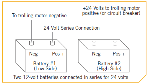
CONNECTING THE BATTERIES IN SERIES (IF REQUIRED FOR YOUR MOTOR)24-Volt SystemsTwo 12-volt batteries are required. The batteries must be wired in series, only as directed in the wiring diagram, to provide 24 volts.
- Make sure that the motor is switched off (speed selector on “0”).
- Connect a connector cable to the positive ( + ) terminal of battery 1 and to the negative ( – ) terminal of battery 2.
- Connect positive ( + ) red motor lead to positive ( + ) terminal on battery 2.
- Connect negative ( – ) black motor lead to negative ( – ) terminal of battery 1.
WARNING:
- For safety reasons do not switch the motor on until the propeller is in the water. If installing a leadwire plug, observe proper polarity and follow instructions in your boat owner’s manual.
- For safety reasons, disconnect the motor from the battery or batteries when the motor is not in use or while the battery/batteries are being charged.
- Improper wiring of 24/36 volt systems could cause battery explosion.
- Keep leadwire wing nut connections tight and solid to battery terminals.
- Locate battery in a ventilated compartment.
MOTOR WIRING DIAGRAM
RIPTIDE EDGEThe following Motor Wiring Diagram applies to all Riptide Edge Foot Control models.
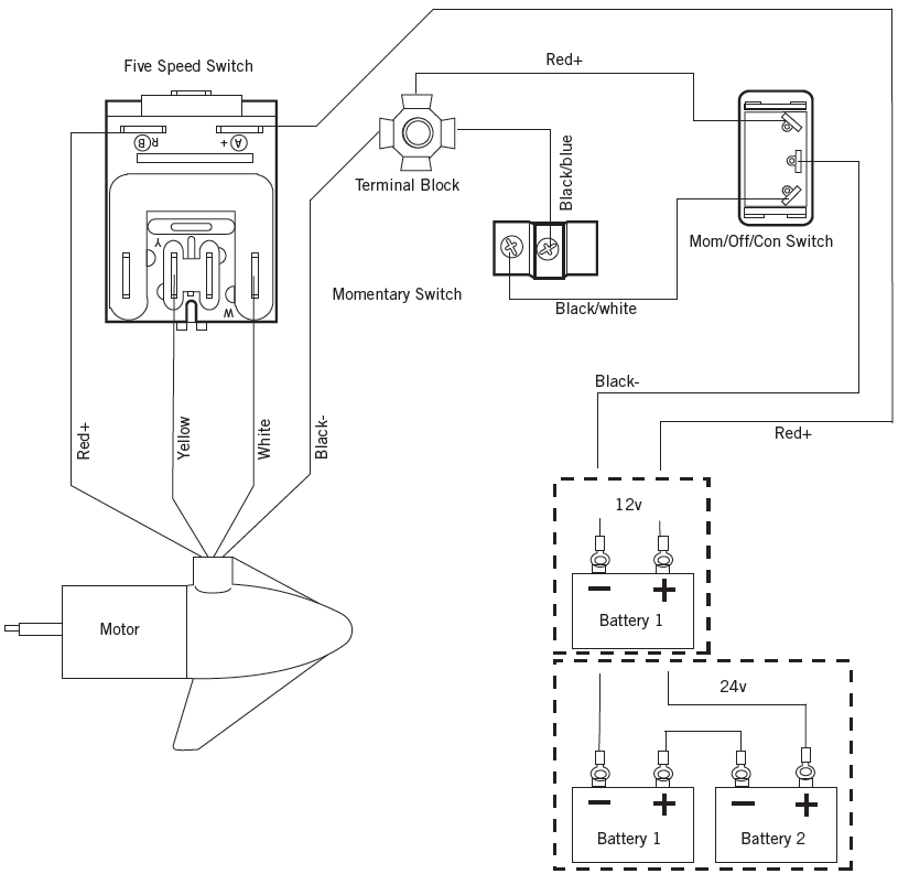
NOTICE: This is a multi-voltage diagram. Double-check your motor’s voltage for proper connections. Over-Current Protection Devices are not shown in this illustration.
USING & ADJUSTING THE MOTOR
MOUNT FEATURESBecome familiar with the features of the motor to maximize the capabilities this product offers.
- The motor Mount is designed to fold back and lock the motor flat on the deck when not in use and to provide secure stowage for transport.
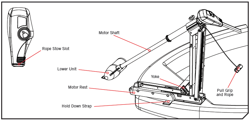
- The Pull Grip and Rope releases the lock bar, which automatically engages when the unit is lowered or raised into position. The Pull Grip and Rope should be used to both lower and raise the unit.
- The Motor Rest positions the Lower Unit as it comes in contact with the nose of the mount and guides it onto the Motor Rest.
- The Tube Lock captures the Motor Shaft and keeps the Lower Unit centered on the Motor Rest.
- The Hold Down Strap must be used to place pressure on the motor shaft to hold the lower unit tightly against the Motor Rest when stowed.
- The Pull Grip and Rope can be stored by placing the Pull Grip into the Rope Stow Slot on the control box of the motor.
WARNING
- The prop may turn on unexpectedly if the control board fails. Prevent injury from a turning propeller and always know how to quickly disengage the power.
- The Riptide Edge is not intended to be a primary propulsion motor. Heavy use of the motor can cause elevated motor temperatures, which can be increased by an excessively hot operating environment. Use care when handling the Control Head and Foot Pedal to avoid burns or injuries from excessive heat. In the event that the motor or speed control would break, always be prepared to take manual control of the boat.
- Be alert for unexpected boat movement when operating the Riptide Edge. The boat may encounter sharp turns and jolts if the steering is changed sharply or if broad changes in speed are made while operating. Maintain balance and observe safe motor operation.
STOWING AND DEPLOYING THE MOTOR
WARNING
- When stowing or deploying the motor, keep fingers clear of all hinge and pivot points and all moving parts. Practice proper ergonomics when stowing and deploying the motor to prevent injury.
- Moving the motor creates a variety of pinch points. The Control Head will create a pinch point if the Depth Adjustment Knob is loosened and the Control Head slides to the top of the Mount. Grasp the Shaft and prevent it from sliding all the way down to prevent the pinch point. Grasp the motor away from the area that may come in contact with another area of the motor to prevent injury.
- When the motor is being transported, on water or land, it is important to place the motor completely out of water. The motor should be positioned up close to the Mount. Always secure the Depth Adjustment Knob and slide the collar down to the top of the Mount for added security during transport and then secure the Hold Down Strap. This provides a secure stow and holds the motor in place during transportation when it is subject to high levels of shock and vibration. Failure to secure the motor may result in injury or damage to the unit.
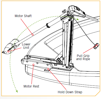
a. To Deploy the Motor, simply pull back and lift the motor off of the mount with the Pull Grip and Rope. Lower the motor into the water using the Pull Grip and Rope. The motor will lock into the deployed position automatically.b. To Stow the Motor, pull back and lift the motor out of the water with the Pull Grip and Rope. Lower the motor Lower Unit onto the Motor Rest using the Pull Grip and Rope. The motor will lock into the stowed position automatically. Wrap the Hold Down Strap over top of the Motor Shaft to secure the motor.
Adjusting the Depth of the Motor
When setting the depth be sure the top of the motor is submerged at least 12” to avoid churning or agitation of surface water. The propeller must be completely submerged.
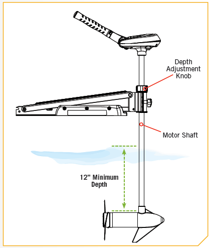
a. With the motor deployed, firmly grasp the Outer Shaft or Control Head and hold it steady.b. Loosen the Depth Adjustment Knob until the Shaft slides freely.c. Raise or lower the motor to the desired depth.d. Turn the motor Control Head to the desired position.e. Tighten the Depth Adjustment Knob to secure the motor in place.
NOTICE: Be sure the top of the motor is submerged at least 12” below the surface of the water to avoid churning or agitation of surface water.
The motor head will create a pinch point if the Depth Adjustment Knob is loosened and the motor Control Head slides to the top of the Mount. Grasp the Shaft and prevent it from sliding all the way down to prevent the pinch point. Grasp the motor away from the area that may come in contact with another area of the motor to prevent injury.
Adjusting the SteeringAdjust the Steering Tension Knob to provide enough tension to allow the motor to turn freely, yet remain in any position without being held or tighten the knob to place the motor in a preset position to leave your hands free for fishing.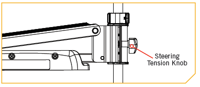
Controlling Speed & Direction with the Tiller
This motor offers variable forward and reverse speeds. The speed control may be operated in either direction, forward or reverse. Turn the tiller handle counterclockwise from (OFF) to increase reverse speed and clockwise from (OFF) to increase forward speed. Speed decreases as you approach (OFF) from either direction.
WARNING:
- When the motor is not in use, always turn the Tiller handle to “OFF”. If the handle is set or accidentally engaged or bummped and is not positioned to “OFF” the prop will turn on unexpectedly. The prop may also turn on unexpectedly if the control board or 5 position switch fails. Prevent injury from a turning propeller and always know how to quickly disengage the power or correct the Tiller to turn the prop off.
- The Riptide Edge is not intended to be a primary propulsion motor. Heavy use of the motor can cause elevated motor temperatures, which can be increased by an excessively hot operating environment. Use care when handling the control head to avoid burns or injuries from excessive heat. In the event that the motor or speed control would break, always be prepared to take manual control of the boat.
PUSH-TO-TEST BATTERY METER
This motor is equipped with a “push-to-test” battery meter. The LED light provides an accurate display of the remaining charge in the battery. It is only accurate when the motor is off.The meter reads as:
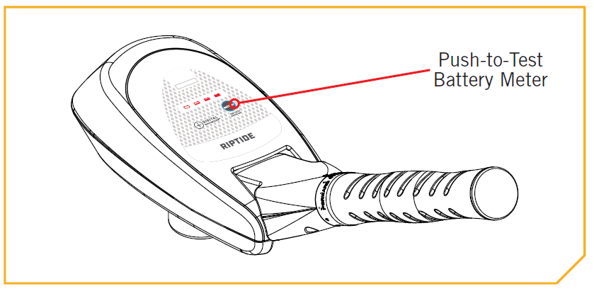
- One light indicates recharge.
- Two lights indicate low charge.
- Three lights indicate good charge.
- Four lights indicate full charge.
Adjusting the Tilt/Extend Tiller
Your trolling motor features 7 usable handle tilt positions: 45°, 30°, and 15° up and down from the 0° (horizontal) position. To use the down positions, you must first press the release button located on the left underside of the pivot handle.Your trolling motor handle also features a unique stow position, that is useful for limiting the amount of space required for storage or travel.
a. First press the release button located on the left underside of the pivot handle, then push the handle down until you feel the handle “lock in” to the stowed position. This will be almost parallel to the motor shaft.
b. To extend the handle, pull the handle towards you to the desired position. The handle will extend a full 6 inches. To retract, push the handle in until it meets the face of the motor control head.
WARNING
The position of the Tilt/Extend Tiller may create a pinch point between it and the Control Head. Grasp the motor away from the area that may come in contact with another area of the motor to prevent injury.
CAUTIONBefore attempting to put the handle in the stowed position, the speed selector must be in the OFF/STOW position. Failure to do so will damage the internal mechanism.
SERVICE & MAINTENANCE
PROPELLER REPLACEMENT
- 1/2” Open End Wrench (70 lbs thrust or lower)
- 9/16” Open End Wrench (80 lbs thrust or higher)
- Screwdriver
INSTALLATION
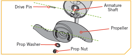
a. Disconnect the motor from all sources of power prior to changing the propeller.b. Hold the propeller and loosen the Prop Nut with a pliers or a wrench.c. Remove the Prop Nut and Prop Washer.d. Turn the old prop to horizontal and pull it straight off. If drive pin falls out, push it back in.
NOTICE: If the Drive Pin is sheared or broken, you will need to hold the shaft stationary with a flat blade screwdriver pressed into the slot on the end of the shaft while you loosen the Prop Nut.
CAUTION: Disconnect the motor from the battery before beginning any prop work or maintenance. If the prop does not readily slide off, take care to not bend the Armature Shaft while removing the prop by pulling the prop evenly off the Armature Shaft. 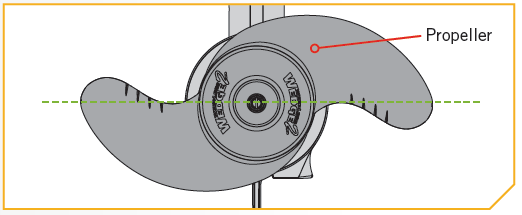
CAUTION: Do not over tighten as this can damage the prop.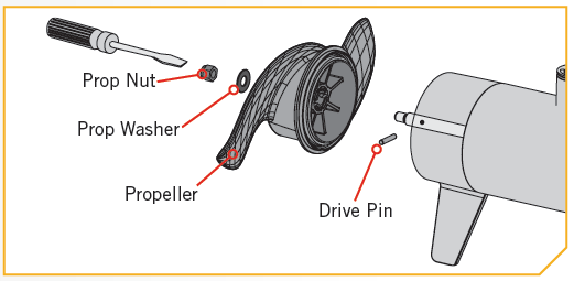
GENERAL MAINTENANCE
- After use, the entire motor should be rinsed with freshwater, then wiped down with a cloth dampened with an aqueous-based silicone spray. Do not spray water into the ventilation openings in the head of the motor.
- The composite shaft requires periodic cleaning and lubrication for proper retraction and deployment. A coating of an aqueous based silicone spray will improve operation.
- The propeller must be inspected and cleaned from weeds and fishing line after every use. Fishing line and weeds can get behind the prop, damage the seals and allow water to enter the motor.
- Verify the prop nut is secure each time the motor is used.
- To prevent accidental damage during transportation or storage, disconnect the battery whenever the motor is off of the water. For prolonged storage, lightly coat all metal parts with an aqueous based silicone spray.
- For maximum battery life recharge the battery(s) as soon as possible after use. For maximum motor performance restore battery to full charge prior to use.
- Keep battery terminals clean with fine sandpaper or emery cloth.
- The propeller is designed to provide weed free operation with very high efficiency. To maintain this top performance, the leading edge of the blades must be kept smooth. If they are rough or nicked from use, restore to smooth by sanding with fine sandpaper.
- Inspect the Pull Grip and Cable and Hold Down Strap before each use and replace if they shows signs of wear.
TROUBLESHOOTING
- Motor fails to run or lacks power:• Check battery connections for proper polarity.• Make sure terminals are clean and corrosion free. Use fine sandpaper or emery cloth to clean terminals.• Check battery water level. Add water if needed.
- Motor loses power after a short running time:• Check battery charge. If low, restore to full charge.
- Motor is difficult to steer:• Loosen the steering tension knob on the bracket.• Lubricate the composite shaft.
- You experience prop vibration during normal operation:• Remove and rotate the prop 180°. See removal instructions in the Propeller Replacement section.
- Experiencing interference with your fishfinder:• You may, in some applications, experience interference in your depth finder display. We recommend that you use a separate deep cycle marine battery for your trolling motor and that you power the depth finder from the starting/cranking battery. If problems still persist, call our service department at 1-800-227-6433.
NOTICE: For all other malfunctions, visit an Authorized Service Center. You can search for an Authorized Service Center in your area by visiting our Authorized Service page, found online at minnkotamotors.com, or by calling our customer service number at 800-227-6433.
FOR FURTHER TROUBLESHOOTING AND REPAIR
We offer several options to help you troubleshoot and/or repair your product. Please read through the options listed below.
- Buy Parts OnlineYou can buy parts on-line directly from our website at minnkotamotors.com. Orders confirmed by 12 Noon Central Time, with Overnight Shipping selected, should ship the same business day if the parts are in stock. All other orders should ship within the next 3 business days, depending on the shipment method chosen, and if the parts are in stock.
- Frequently Asked QuestionsWe have FAQs available on our website to help answer all of your Minn Kota questions. Visit minnkotamotors.com and click on “Frequently Asked Questions” to find an answer to your question.
- Call Us (for U.S. and Canada)Our consumer service representatives are available Monday – Friday between 7:00 a.m. – 4:30 p.m. CST at 800-227-6433. If you are calling to order parts, please have the 11-character serial number from your product, specific part numbers, and credit card information available. This will help expedite your call and allow us to provide you with the best consumer service possible. You can reference the parts list located in your manual to identify the specific part numbers.
- Email UsYou can email our consumer service department with questions regarding your Minn Kota products. To email your question, visit minnkotamotors.com and click on “Support”.
- Authorized Service CentersMinn Kota has over 800 authorized service providers in the United States and Canada where you can purchase parts or get your products repaired. Please visit our Authorized Service Center page on our website to locate a service provider in your area.
COMPLIANCE STATEMENTS
ENVIRONMENTAL COMPLIANCE STATEMENTIt is the intention of JOME to be a responsible corporate citizen, operating in compliance with known and applicable environmental regulations, and a good neighbor in the communities where we make or sell our products.
WEEE DIRECTIVEEU Directive 2002/96/EC “Waste of Electrical and Electronic Equipment Directive (WEEE)” impacts most distributors, sellers, and manufacturers of consumer electronics in the European Union. The WEEE Directive requires the producer of consumer electronics to take responsibility for the management of waste from their products to achieve environmentally responsible disposal during the product life cycle.WEEE compliance may not be required in your location for electrical & electronic equipment (EEE), nor may it be required for EEE designed and intended as fi xed or temporary installation in transportation vehicles such as automobiles, aircraft, and boats. In some European Union member states, these vehicles are considered outside of the scope of the Directive, and EEE for those applications can be considered excluded from the WEEE Directive requirement.
This symbol (WEEE wheelie bin) on product indicates the product must not be disposed of with other household refuse. It must be disposed of and collected for recycling and recovery of waste EEE. Johnson Outdoors Inc. will mark all EEE products in accordance with the WEEE Directive. It is our goal to comply in the collection, treatment, recovery, and environmentally sound disposal of those products; however, these requirements do vary within European Union member states. For more information about where you should dispose of your waste equipment for recycling and recovery and/or your European Union member state requirements, please contact your dealer or distributor from which your product was purchased.
DISPOSALMinn Kota motors are not subject to the disposal regulations EAG-VO (electric devices directive) that implements the WEEE directive. Nevertheless never dispose of your Minn Kota motor in a garbage bin but at the proper place of collection of your local town council.Never dispose of battery in a garbage bin. Comply with the disposal directions of the manufacturer or his representative and dispose of them at the proper place of collection of your local town council.
FCC COMPLIANCE
This device complies with Part 15 of the FCC rules. Operation is subject to the following two conditions:
- This device may not cause harmful interference.
- This device must accept any interference that may be received, including interference that may cause undesired operation.
Changes or modifications not expressly approved by Johnson Outdoors Marine Electronics, Inc. could void the user’s authority to operate this equipment.
NOTICE: This equipment has been tested and found to comply with the limits for a Class B digital device, pursuant to part 15 of the FCC Rules. These limits are designed to provide reasonable protection against harmful interference in a residential installation. This equipment generates, uses and can radiate radio frequency energy and, if not installed and used in accordance with the instructions, may cause harmful interference to radio communications. However, there is no guarantee that interference will not occur in a particular installation. If this equipment does cause harmful interference to radio or television reception, which can be determined by turning the equipment off and on, the user is encouraged to try to correct the interference by one or more of the following measures:
- Reorient or relocate the receiving antenna.
- Increase the separation between the equipment and receiver.
- Connect the equipment into an outlet on a circuit different from that to which the receiver is connected.
- Consult the dealer or an experienced radio/TV technician for help.
INDUSTRY CANADA COMPLIANCEThis product meets the applicable Industry Canada technical specifications. Operation is subject to the following two conditions: (1) this device may not cause interference, and (2) this device must accept any interference, including interference that may cause undesired operation of the device.Changes or modifications not expressly approved by Johnson Outdoors Marine Electronics, Inc. could void the user’s authority to operate this equipment.
ENVIRONMENTAL RATINGSAmbient operating temperature range: -10C to 50CAmbient operating humidity range: 5% to 95%Maximum operating altitude: 10,000 feet
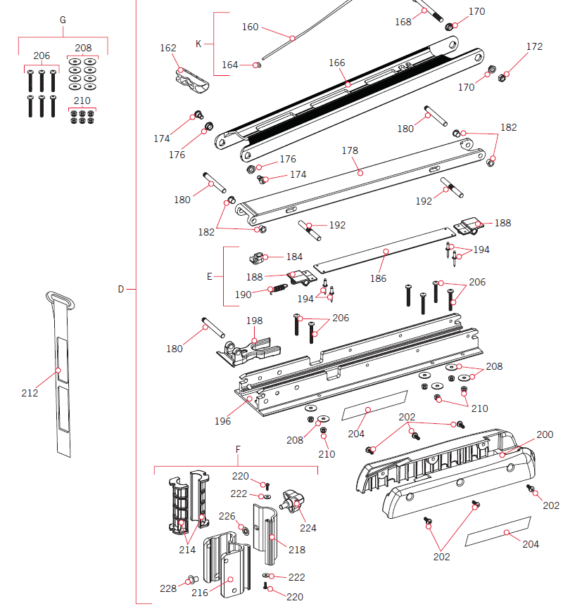
PARTS DIAGRAM & PARTS LIST
RIPTIDE EDGE 55 – 55 LBS THRUST – 12 VOLT – 52” SHAFTThis page provides Minn Kota® WEEE compliance disassembly instructions. For more information about where you should dispose of your waste equipment for recycling and recovery and/or your European Union member state requirements, please contact your dealer or distributor from which your product was purchased. Tools required, but not limited to: flat head screw driver, Phillips screw driver, socket set, pliers, wire cutters.
Control Head Parts Diagram
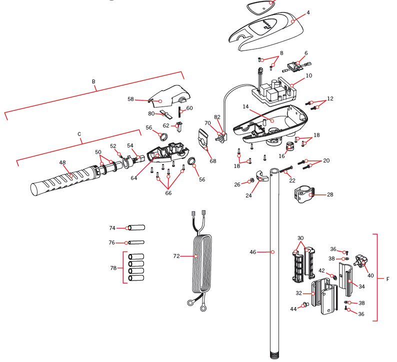
Control Head Parts List
| Assembly | Part # | Description | Notes | Quantity |
| B | 2990468 | HANDLE ASM, VAR SPD, FW/SW | 1 | |
| C | 2990466 | HANDLE ASM, VAR.SPEED, TRAXXIS | 1 | |
| F | 2771832 | HINGE BASE/DOOR ASSY,SW | 1 | |
| Item | Part # | Description | Notes | Quantity |
| 2 | 2195662 | DECAL-COVER, RT55 SE, SM | 1 | |
| 4 | 2060299 | COVER, CONTROL BOX, SW | 1 | |
| 6 | 2074080 | BATTERY METER, 12V, SW | 1 | |
| 8 | 2043427 | SCREW-#8 X 7/8 PPH TY BT SS | 2 | |
| 10 | 2184026 | CTRL BRD ASSY,12V TRAXXIS | 1 | |
| 12 | 2303434 | SCREW-#8-32 X 5/8 MACH PHCR SS | 2 | |
| 14 | 2062538 | CONTROL BOX, CAST, SW | 1 | |
| 16 | 2062905 | STRAIN RELIEF,HEYCO 1876 | 1 | |
| 18 | 2303412 | SCREW-#6-20 X 5/8 SELF TAP | 6 | |
| 20 | 2063410 | SCREW-#10-32 X 3/4″ CAP SS | 2 | |
| 22 | 2093400 | SCREW-#10-24 X 1-7/8 PPH SS | 1 | |
| 24 | 2061529 | COLLAR-CTRL BOX (SW) | 1 | |
| 26 | 2333101 | NUT-HEX #10-24 UNC-2B NYL SS | 1 | |
| 28 | 2991521 | CAM LOCK/DEPTH COLLAR ASY | 1 | |
| 30 | 2261537 | HINGE SLEEVE | 2 | |
| 32 | 2261894 | HINGE BASE SW | 1 | |
| 34 | 2261898 | HINGE DOOR EXTRUSION,SW | 1 | |
| 36 | 2332100 | SCREW-#8-32 X 3/8 MACHINE | 2 | |
| 38 | 2261732 | WASHER-#8, NYLON BLACK | 2 | |
| 40 | 2260906 | KNOB-SOFT GRIP,HG/DR,SS | 1 | |
| 42 | 2261728 | WASHER-RETAINING 3/8 THREADS | 1 | |
| 44 | 2264703 | INSERT-THREADED (EDGE) | 1 | |
| 46 | 2002014 | TUBE (COMPOSITE) 52″ WHITE | 1 | |
| 48 | ✖ | GRIP-HANDLE, RAW, TRAXXIS | 1 | |
| 50 | 2060015 | BEARING, HANDLE 2990455 | 2 | |
| 52 | 2063405 | SCREW-#6 X 1/2″ PFH SS TY AB | 1 | |
| 54 | 2994092 | YOKE ASY,VAR.2990455 | 1 | |
| 56 | 2060005 | BEARING-HANDLE PIVOT | 2 | |
| 58 | 2060900 | PIVOT HANDLE, TOP | 1 | |
| 60 | 2302745 | SPRING-RELEASE BUTTON (SS | 1 | |
| 62 | 2063700 | BUTTON-RELEASE | 1 | |
| 64 | 2060905 | PIVOT HANDLE, BTTM | 1 |
| Item | Part # | Description | Notes | Quantity |
| 66 | 2303412 | SCREW-#6-20 X 5/8 SELF TAP | 6 | |
| 68 | 2062715 | SPRING, DETENT, HANDLE TILT | 1 | |
| 70 | 2061700 | WASHER, POT HOLDER | 1 | |
| 72 | 2992521 | LEADWIRE ASSY-HC BOW VAR 96 | 1 | |
| 74 | 2305415 | SHRINK TUBE-.472 ID X 2.25″ | 1 | |
| 76 | 2305410 | SHRINK TUBE-.315 OD X 2.25″ | 1 | |
| 78 | 2305403 | SHRINK TUBE-.500 IDX1.0″ ADHSV | 4 | |
| 80 | 2302742 | SPRING-DETENT (OFF) | 1 | |
| 82 | 2888411 | POTENTIOMETER ASSY | 1 | |
| 2197118 | MANUAL, RT/EDGE | 1 | ||
| 2194959 | PARTS LIST, RT55/SE/L&D | 1 | ||
| 2015800 | HANG TAG “CAUTION..TILT HINGE” | 1 | ||
| 2015801 | HANG TAG-PINK “CAUTION..HG/DR” | 1 |
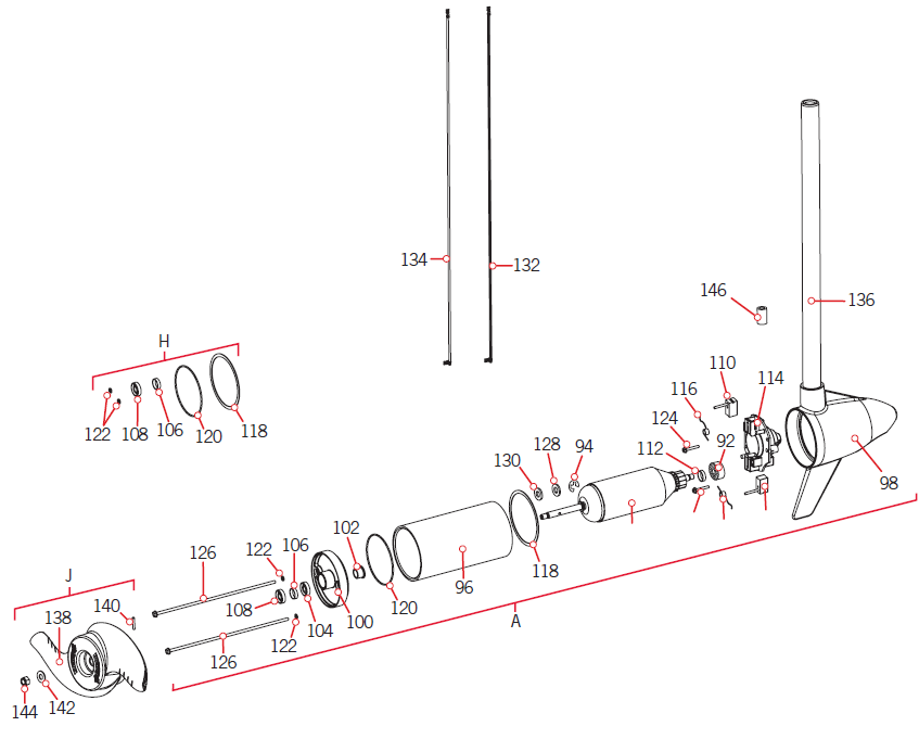
Motor Parts Diagram
| Assembly | Part # | Description | Notes | Quantity |
| A | 2097091 | MTR ASY 12V 3.62 VS 55# SW | 1 | |
| H | 2888460 | SEAL & O-RING KIT TURBO PRO | 1 | |
| J | 1378131 | PROP IND 2091160 WDLS WDG II | 1 | |
| Item | Part # | Description | Notes | Quantity |
| 90 | 2-100-117A | ARM ASY 12V 3.62 55#2.88″ | 1 | |
| 92 | 140-010 | BEARING – BALL | 1 | |
| 94 | 788-015 | RETAINING RING | 1 | |
| 96 | ✖ | CTR HSG ASM 3.6″ SW MAGNETIZED | 1 | |
| 98 | 421-336 | HSG BRSH END 3.62 SW TXT/WHITE | 1 | |
| 100 | 2-400-337A | PLAIN END HSG ASY 3.6 TX/W | 1 | |
| 102 | 144-049 | BEARING – FLANGE | 1 | |
| 104 | 880-003 | SEAL | 1 | |
| 106 | 725-035 | PAPER TUBE – SEAL BORE | 1 | |
| 108 | 880-006 | SEAL WITH SHIELD | 1 | |
| 110 | 188-036 | BRUSH ASSEMBLY 3.625 | 2 | |
| 112 | 725-050 | PAPER TUBE – BRUSH RETENTION | 1 | |
| 114 | 738-036 | BRUSH PLATE WITH HOLDER 3.625 | 1 | |
| 116 | 975-040 | SPRING – TORSION | 2 | |
| 118 | 337-036 | GASKET | 1 | |
| 120 | 701-081 | O-RING | 1 | |
| 122 | 701-008 | O-RING | *THRU-BOLT* | 2 |
| 124 | 830-007 | SCREW, # 8-32 | 2 | |
| 126 | 830-042 | THRU BOLT 10-32 X 8.83 | 2 | |
| 128 | 990-067 | WASHER – STEEL THRUST | 1 | |
| 130 | 990-070 | WASHER – NYLATRON | 1 | |
| 132 | 640-008 | LEADWIRE BLK 10AWG 63-1/2″ GPT | 1 | |
| 134 | 640-107 | LEADWIRE RED 10AWG 65-1/2″ GPT | 1 | |
| 136 | 2002014 | TUBE (COMPOSITE) 52″ WHITE | 1 | |
| 138 | 2091160 | PROP-WW2 (3 5/8″) REAMED | 1 | |
| 140 | 2092600 | PIN-DRIVE 1.06″ LG (SS) | 1 | |
| 142 | 2151726 | WASHER-5/16 STD (S/S) | 1 | |
| 144 | 2053101 | NUT-PROP,NYLOC (MED) 5/16 SS | 1 | |
| 146 | 2307317 | FERRITE BEAD, SHORT | 1 |
| Assembly | Part # | Description | Notes | Quantity |
| D | 2991648 | MNT ASM EDGE SW SHORT | 1 | |
| E | 2993811 | LATCH STRAP ASSEMBLY STD | 1 | |
| F | 2771832 | HINGE BASE/DOOR ASSY,SW | 1 | |
| G | 2994838 | BAG ASSY-(BOLTS,NUTS,WASHERS) | 1 | |
| K | 2994886 | BAG ASSY, PULL GRIP/WASHER | 1 | |
| Item | Part # | Description | Notes | Quantity |
| 160 | 2251601 | ROPE (44.5″), MAXXUM MNT | 1 | |
| 162 | 2150400 | PULL-GRIP | 1 | |
| 164 | 2151700 | WASHER-EYE SHAFT(.562 OD) SS | 1 | |
| 166 | 2264271 | ARM-UPPER, SHORT | 1 | |
| 168 | 2263506 | BOLT 3/8-16 UNC X 4.25″ SS | 1 | |
| 170 | 2267303 | BUSHING-PWDR MTL 3/8 ID SS | 2 | |
| 172 | 2263115 | NUT-NYLOK JAM 3/8-16 UNC SS | 1 | |
| 174 | 2263510 | BOLT-SHOULDER, SS | 2 | |
| 176 | 2267302 | BUSHING-PWDR MTL 7/16 ID SS | 2 | |
| 178 | 2264343 | LWR ARM EXTRUSION,STD,SW | 1 | |
| 180 | 2260504 | PIN-PIVOT SS | 3 | |
| 182 | 2266002 | BEARING-NYLINER 3/8″ SHAFT | 4 | |
| 184 | 2262310 | GUIDE-ROPE | 1 | |
| 186 | 2263605 | LATCH STRAP, LOWER ARM | 1 | |
| 188 | 2261902 | BRACKET-LATCH | 2 | |
| 190 | 2262709 | SPRING-LATCH PIN | 1 | |
| 192 | 2260502 | PIN-LATCH SS | 2 | |
| 194 | 2268602 | RIVET 1/8″ BUTTONHEAD BLIND SS | 4 | |
| 196 | 2266503 | BOWPLATE EXTRUSION,STD,SW | 1 | |
| 198 | 2261544 | YOKE-TUBE | 1 | |
| 200 | 2263906 | MOTOR REST, A/T, WHT | 1 | |
| 202 | 2332104 | SCREW-1/4-20 X 5/8 S/S | 6 | |
| 204 | 2265703 | DECAL, MOTOR REST RT EDGE SW | 2 | |
| 206 | 2263462 | SCREW-1/4-20 X 2″ S/S PPH ADJT | 6 | |
| 208 | 2261713 | WASHER-1/4 FLAT 18-8 SS | 6 | |
| 210 | 2263103 | NUT-1/4-20 NYLOCK SS | 6 | |
| 212 | 2263805 | STRAP-HOOK&LOOP,22.5″1-PC.BRKT | 1 | |
| 214 | 2261537 | HINGE SLEEVE | 2 | |
| 216 | 2261894 | HINGE BASE SW | 1 | |
| 218 | 2261898 | HINGE DOOR EXTRUSION,SW | 1 |
| Item | Part # | Description | Notes | Quantity |
| 220 | 2332100 | SCREW-#8-32 X 3/8 MACHINE | 2 | |
| 222 | 2261732 | WASHER-#8, NYLON BLACK | 2 | |
| 224 | 2260906 | KNOB-SOFT GRIP,HG/DR,SS | 1 | |
| 226 | 2261728 | WASHER-RETAINING 3/8 THREADS | 1 | |
| 228 | 2264703 | INSERT-THREADED (EDGE) | 1 |
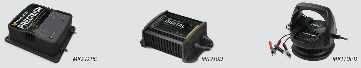
RECOMMENDED ACCESSORIES
ON-BOARD & PORTABLE BATTERY CHARGERSStop buying new batteries and start taking care of the ones you’ve got. Many chargers can actually damage your battery over time – creating shorter run times and shorter overall life. Digitally controlled Minn Kota chargers are designed to provide the fastest charge that protect and extend battery life.
TALON SHALLOW WATER ANCHORIntroducing the all-new, sleek redesigned Talon. Talon is the only shallow water anchor with up to 15’ of anchoring depth, multiple anchoring modes, and control from the bow, transom, console, remote or mobile device.
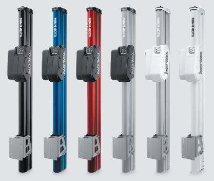
BUILT-IN WORK LIGHT: Lets you tie lines and work from the transom any time of day — or night. Includes both white and blue LED lights with three brightness settings.BLUETOOTH® CONNECTIVITY: Lets you control Talon from your mobile device and easily update it. Also opens up communication to other control options.UP TO 15’ DEEP: Control more water and catch more fish with the first 15’ shallow water anchor.MORE CONTROL OPTIONS:
- Control Panel
- Wireless Remote
- Mobile App
- Wireless Foot Switch
- Humminbird® Connectivity
- i-Pilot® &
- i- Pilot LinkTM Remote
MINN KOTA ACCESSORIES
We offer a wide variety of trolling motor accessories, including:
- 60-Amp Circuit Breaker
- Mounting Brackets
- Stabilizer Kits
- Extension Handles
- Battery Connectors
- Battery Boxes
- Quick Connect Plugs
References
[xyz-ips snippet=”download-snippet”]