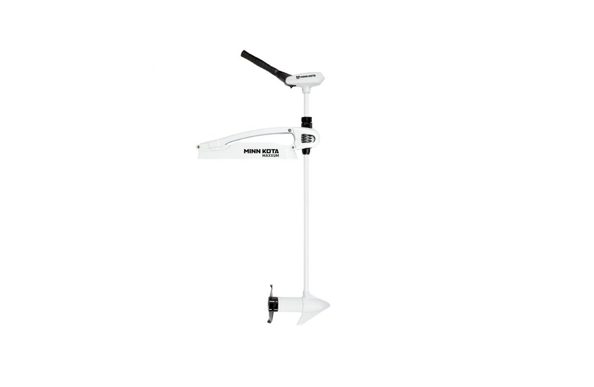
Riptide Maxxum Bow-Mount Trolling Motor
RIPTIDE® MAXXUM®BOW-MOUNT TROLLING MOTOROwner’s Manual
INTRODUCTION
THANK YOUThank you for choosing Minn Kota. We believe that you should spend more time fishing and less time positioning your boat. That’s why we build the smartest, toughest, most intuitive trolling motors on the water. Every aspect of a Minn Kota trolling motor is thought out and rethought until it’s good enough to bear our name. Countless hours of research and testing provide you the Minn Kota advantage that can truly take you “Anywhere. Anytime.” We don’t believe in shortcuts. We are Minn Kota. And we are never done helping you catch more fish.
REGISTRATIONRemember to keep your receipt and immediately register your trolling motor. A registration card is included with your motor or you can complete registration on our website at minnkotamotors.com.SERIAL NUMBERYour Minn Kota 11-character serial number is very important. It helps to determine the specific model and year of manufacture. When contacting Consumer Service or registering your product, you will need to know your product’s serial number. We recommend that you write the serial number down so that you have it available for future reference.NOTICE: The serial number on your Riptide Maxxum islocated under the tiller handle.MOTOR INFORMATION (For Consumer Reference Only)Model:Serial Number:Purchase Date:Store Where Purchased:
Made by Minn Kota Johnson Outdoors Marine Electronics, Inc. 121 Power Drive Mankato, MN 56001 USA Trolling Motors Produced in 2012
Maxxum 80/52 MODEL 1368640SER NO M365 MK12345EXAMPLE
NOTICE: Do not return your Minn Kota motor to your retailer. Your retailer is not authorized to repair or replace this unit.You may obtain service by: calling Minn Kota at (800) 227-6433; returning your motor to the Minn Kota Factory Service Center; sending or taking your motor to any Minn Kota authorized service center. A list of authorized service centers is available on our website, at minnkotamotors.com. Please include proof of purchase, serial number and purchase date for warranty service with any of the abe options.
2 | minnkotamotors.com
©2021 Johnson Outdoors Marine Electronics, Inc.
TABLE OF CONTENTSSAFETY CONSIDERATIONS ……………………………………………………………………………………. 4 WARRANTY……………………………………………………………………………………………………… 5 FEATURES ………………………………………………………………………………………………………. 7 INSTALLATION ………………………………………………………………………………………………….. 8Installation of Motor to Mount……………………………………………………………………….. 8 Installation of the Bow-mount……………………………………………………………………… 10 Installation of the Hold Down Strap………………………………………………………………. 11 BATTERY & WIRING INSTALLATION………………………………………………………………………… 12 Boat Rigging & Product Installation………………………………………………………………. 12 Conductor Gauge and Circuit Breaker Sizing Table …………………………………………… 12 Selecting the Correct Batteries…………………………………………………………………….. 13 Additional Considerations…………………………………………………………………………… 13 Connecting the Batteries ……………………………………………………………………………. 14 Connecting the Batteries in Series ……………………………………………………………….. 15 MOTOR WIRING DIAGRAM…………………………………………………………………………………… 16 USING & ADJUSTING THE MOTOR………………………………………………………………………….. 18 Mount Features ……………………………………………………………………………………….. 18 Stowing & Deploying the Motor ……………………………………………………………………. 19 Adjusting the Depth of the Motor …………………………………………………………………. 21 Controlling Speed and Direction with the Tiller ………………………………………………… 22 Adjusting the Tilt/Extend Tiller …………………………………………………………………….. 22 SERVICE & MAINTENANCE………………………………………………………………………………….. 24 Propeller Replacement………………………………………………………………………………. 24 General Maintenance ………………………………………………………………………………… 25 Troubleshooting ……………………………………………………………………………………….. 25 For Further Troubleshooting And Repair…………………………………………………………. 26 COMPLIANCE STATEMENTS…………………………………………………………………………………. 27 PARTS DIAGRAM & PARTS LIST ……………………………………………………………………………. 29
©2021 Johnson Outdoors Marine Electronics, Inc.
minnkotamotors.com | 3
SAFETY CONSIDERATIONSPlease thoroughly read the user manual. Follow all instructions and heed all safety and cautionary notices. Use of this motor is only permitted for persons that have read and understood these user instructions. Minors may use this motor only under adult supervision.WARNINGYou are responsible for the safe and prudent operation of your vessel. We have designed your Minn Kota product to be an accurate and reliable tool that will enhance boat operation and improve your ability to catch fish. This product does not relieve you from the responsibility for safe operation of your boat. You must avoid hazards to navigation and always maintain a permanent watch so you can respond to situations as they develop. You must always be prepared to regain manual control of your boat. Learn to operate your Minn Kota product in an area free from hazards and obstacles.WARNINGNever run the motor out of the water, as this may result in injuries from the rotating propeller. The motor should be disconnected from the power source when it is not in use or is off the water. When connecting the power-supply cables of the motor to the battery, ensure that they are not kinked or subject to chafe and route them in such a way that persons cannot trip over them. Before using the motor make sure that the insulation of the power cables is not damaged. Disregarding these safety precautions may result in electric shorts of battery(s) and/or motor. Always disconnect motor from battery(s) before cleaning or checking the propeller. Avoid submerging the complete motor as water may enter the lower unit through control head and shaft. If the motor is used while water is present in the lower unit considerable damage to the motor can occur. This damage will not be covered by warranty.WARNINGTake care that neither you nor other persons approach the turning propeller too closely, neither with body parts nor with objects. The motor is powerful and may endanger or injure you or others. While the motor is running watch out for persons swimming and for floating objects. Persons who lack the ability to run the motor or whose reactions are impaired by alcohol, drugs, medication, or other substances are not permitted to use this motor. This motor is not suitable for use in strong currents. The constant noise pressure level of the motor during use is less than 70dB(A). The overall vibration level does not exceed 2,5 m/sec2.WARNINGWhen stowing or deploying the motor, keep fingers clear of all hinge and pivot points and all moving parts. In the event of unexpected operation, remove power leads from the battery.WARNINGIt is recommended to only use Johnson Outdoors approved accessories with your Minn Kota motor. Using non-approved accessories including to mount or control your motor may cause damage, unexpected motor operation and injury. Be sure to use the product and approved accessories, including remotes, safely and in the manner directed to avoid accidental or unexpected motor operation. Keep all factory installed parts in place including motor and accessory covers, enclosures and guards.
4 | minnkotamotors.com
©2021 Johnson Outdoors Marine Electronics, Inc.
WARRANTYWARRANTY ON MINN KOTA SALTWATER TROLLING MOTORSJohnson Outdoors Marine Electronics, Inc. (“JOME”) extends the following limited warranty to the original retail purchaser only. Warranty coverage is not transferable.Minn Kota Limited Two-Year Warranty on the Entire ProductJOME warrants to the original retail purchaser only that the purchaser’s new Minn Kota saltwater trolling motor will be materially free from defects in materials and workmanship appearing within two (2) years after the date of purchase. JOME will (at its option) either repair or replace, free of charge, any parts found by JOME to be defective during the term of this warranty. Such repair, or replacement shall be the sole and exclusive liability of JOME and the sole and exclusive remedy of the purchaser for breach of this warranty.Minn Kota Limited Lifetime Warranty on Composite ShaftJOME warrants to the original retail purchaser only that the composite shaft of the purchaser’s Minn Kota trolling motor will be materially free from defects in materials and workmanship appearing within the original purchaser’s lifetime. JOME will provide a new composite shaft, free of charge, to replace any composite shaft found by JOME to be defective during the term of this warranty. Providing a new composite shaft shall be the sole and exclusive liability of JOME and the sole and exclusive remedy of the purchaser for breach of this warranty; and purchaser shall be responsible for installing, or for the cost of labor to install, any new composite shaft provided by JOME.Exclusions & LimitationsThis limited warranty does not apply to products that have been used commercially or for rental purposes. This limited warranty does not cover normal wear and tear, blemishes that do not affect the operation of the product, or damage caused by accidents, abuse, alteration, modification, shipping damages, negligence of the user or misuse, improper or insufficient care or maintenance. DAMAGE CAUSED BY THE USE OF OTHER REPLACEMENT PARTS NOT MEETING THE DESIGN SPECIFICATIONS OF THE ORIGINAL PARTS WILL NOT BE COVERED BY THIS LIMITED WARRANTY. The cost of normal maintenance or replacement parts which are not in breach of the limited warranty are the responsibility of the purchaser. Prior to using products, the purchaser shall determine the suitability of the products for the intended use and assumes all related risk and liability. Any assistance JOME provides to or procures for the purchaser outside the terms, limitations or exclusions of this limited warranty will not constitute a waiver of the terms, limitations or exclusions, nor will such assistance extend or revive the warranty. JOME will not reimburse the purchaser for any expenses incurred by the purchaser in repairing, correcting or replacing any defective products or parts, except those incurred with JOME’s prior written permission. JOME’S AGGREGATE LIABILITY WITH RESPECT TO COVERED PRODUCTS IS LIMITED TO AN AMOUNT EQUAL TO THE PURCHASER’S ORIGINAL PURCHASE PRICE PAID FOR SUCH PRODUCT.Minn Kota Service InformationTo obtain warranty service in the U.S., the product believed to be defective, and proof of original purchase (including the date of purchase), must be presented to a Minn Kota Authorized Service Center or to Minn Kota’s factory service center in Mankato, MN. Any charges incurred for service calls, transportation or shipping/freight to/from the Minn Kota Authorized Service Center or factory, labor to haul out, remove, re-install or re-rig products removed for warranty service, or any other similar items are the sole and exclusive responsibility of the purchaser. Products purchased outside of the U.S. must be returned prepaid with proof of purchase (including the date of purchase and serial number) to any Authorized Minn Kota Service Center in the country of purchase. Warranty service can be arranged by contacting a Minn Kota Authorized Service Center or by contacting the factory at 1-800227-6433 or email Products repaired or replaced will be warranted for the remainder of the original warranty period [or for 90 days from the date of repair or replacement, whichever is longer]. For any product that is returned for warranty service that JOME finds to be not covered by or not in breach of this limited warranty, there will be a billing for services rendered at the prevailing posted labor rate and for a minimum of at least one hour.NOTICE: Do not return your Minn Kota product to your retailer. Your retailer is not authorized to repair or replace products.NOTICE: THERE ARE NO EXPRESS WARRANTIES OTHER THAN THESE LIMITED WARRANTIES. IN NO EVENT SHALL ANY IMPLIED WARRANTIES INCLUDINGANY IMPLIED WARRANTIES OF MERCHANTABILITY OR FITNESS FOR PARTICULAR PURPOSE, EXTEND BEYOND THE DURATION OF THE RELEVANT EXPRESS LIMITED WARRANTY. IN NO EVENT SHALL JOME BE LIABLE FOR PUNITIVE, INDIRECT, INCIDENTAL, CONSEQUENTIAL OR SPECIAL DAMAGES. Without limiting the foregoing, JOME assumes no responsibility for loss of use of product, loss of time, inconvenience or other damage.Some states do not allow limitations on how long an implied warranty lasts or the exclusion or limitation of incidental or consequential damages, so the above limitations and/or exclusions may not apply to you. This warranty gives you specific legal rights and you may also have other legal rights which vary from state to state.
©2021 Johnson Outdoors Marine Electronics, Inc.
minnkotamotors.com | 5
KNOW YOUR BOATBow
Port Gunwale
Starboard
Keel Port
Inboard Outboard
Starboard
Transom
Stern Bow
6 | minnkotamotors.com
Hull
Gunwale
Stern ©2021 Johnson Outdoors Marine Electronics, Inc.
FEATURES
Tilt/Extend Tiller Controls: On/Off, Speed, Forward/Reverse and DirectionMotor Rest
Battery MeterDepth Collar Knob Steering Tension KnobBowguard 360° ® Breakaway Protection (On Applicable Models)Lifetime Warranty Flexible Composite Shaft
Cool Quiet Power Motor
Propeller
NOTICE: Specifications subject to change without notice. This diagram is for reference only and may differ from your actual motor.
©2021 Johnson Outdoors Marine Electronics, Inc.
minnkotamotors.com | 7
INSTALLATION
TOOLS AND RESOURCES REQUIRED
· (2) 1/2″ Wrenches · 9/32″ Drill Bit
· A second person to help with the installation
· Standard or Needle Nose Pliers · File or Sandpaper
· Hand Saw · 3/8″ Nut Driver
INSTALLATION
INSTALLATION OF MOTOR TO MOUNT
1
WARNING
Make sure that the Power Cables from the battery are disconnected, or that the breaker, if equipped, is “off.”
a. With the Mount closed, use two 1/2″ Wrenches to remove one of the two Nylock Nuts and Washers from the Upper Pin. Then remove the Pin from Mount.
NOTICE: The two Bushings in the Upper Arm maycome out. If so, keep them for re-assembly.
b. Using a pair of Pliers, remove the Spring Clip from the Lower Pin. Remove the Lower Pin from Mount.
NOTICE: This motor weighs approximately 60 lbs.We recommend having a second person help with the installation.
Upper Arm
Nylock Nuts & WashersBushing Upper Pin
Mount Bushing
Lower Pin
E-Clip
8 | minnkotamotors.com
©2021 Johnson Outdoors Marine Electronics, Inc.
INSTALLATION
2
c. Open the mount by lifting the Upper Arm up and
opening the mount so it lays flat.
WARNING
Carefully lower the Bowguard into place to avoid creating a pinch point between the Bowguard and Mount.
Bowguard Lower Bouguard Ears
d. Align the Lower Arm and the Lower Bowguard Ears. Once aligned, insert the Lower Pin, pushing it through both the Lower Arm and the Bowguard Ears.
Lower Arm
e. Re-install the E-Clips into the Lower Pin.f. Take the Rope and route it under the Lower Pin and through the bottom of the Eyelet and out the top of the Bowguard.
E-Clip Lower Pin
Eyelet RopeLower BouguardEars
3
g. Rotate the Upper Arm back in place to close the
mount.
h. Align the Upper Arm Holes with Upper Bowguard
NOTICE: The two Bushings in the Upper Arm maycome out. Re-assemble them into the Upper Arm making sure the “keys” of the inserts are aligned with the “key” punchouts in the Upper Arm.
Ears and install the Upper Pin.i. Re-install the Washer and Nylock Nut and tighten using two 1/2″ Wrenches.
4
j. Route the Rope through the Pull Grip Handle and
small Washer. Secure it by tying a Figure Eight Knot.
Upper ArmBushing Washer Nylock Nut
Bowguard
Pull Grip Handle
Figure Eight Knot
Washer
©2021 Johnson Outdoors Marine Electronics, Inc.
minnkotamotors.com | 9
INSTALLATION
Installation of the Bow-mount
Please review the following guidelines before beginning the installation of the Bow-mount:
NOTICE: We recommend that you have another person
· The Motor should be mounted as close to the centerline or keel
help with this installation.
of the boat as possible when it is deployed.
· Make sure bow area under the chosen location is clear and unobstructed for drilling.
· Make sure the Motor Rest is positioned far enough beyond the edge of the boat. The motor, as it is lowered into the water or raised
into the boat, must not encounter any obstructions.
1
a. Review the mounting considerations at the
beginning of this section. Place the Mount as close
to the centerline or keel of the boat as possible,
with the motor in the stowed position, on the deck
of the boat. Check placement with the motor in the
stowed and deployed positions.
WARNING
For installation, do not remove the shaft/motor from the
Bowguard. The Bowguard spring is under tension and must
Keel
always remain secured. Latch and Door models can be
removed from the mount if needed.
2
b. Once in position, determine which bolt pattern to
use. Mark at least 4 of the holes (2 on each side) in
the Bow Plate and drill through with a 9/32″ Drill Bit. Either pattern may be used when installing the
Pattern 1
motor. Pattern 1 is the Minn Kota 3″ bolt pattern
standard motors and Pattern 2 is the alternate 4″
Hold Down Strap
Bow
bolt pattern commonly used.
c. Install the Hold Down Strap between the Motor and deck of boat between second and third set of Mounting Holes. The hook and loop side of the strap should face down and the metal loop should be outboard.d. Mount the Plate to the bow through the drilled holes using the provided (1/4-20 x 3-1/2″) bolts, nuts and washers.
Pattern 2NOTICE: To prevent seizing of the stainless steel hardware,do not use high speed installation tools. Wetting the screws or applying an anti-seize may help prevent seizing.
NOTICE: If possible, secure all sets of mountingbolts, nuts and washers.
10 | minnkotamotors.com
©2021 Johnson Outdoors Marine Electronics, Inc.
Installation of the Hold Down StrapThe Hold Down Strap is not included on all models.
1
a. Before mounting the trolling motor place the Hold Down Strap under the Bow-mount between the
1a Bow-Mount
Mounting Holes near the back of the motor rest with
the hook and loop side of the strap facing down.
b. Secure the Bow-mount with the Mounting Bolts to capture the Hold Down Strap as noted in the Installation of the Bow-mount Section of this Manual.c. To secure, stow the motor, and then pull the Hold Down Strap through the rectangular Ring until snug. Press the hook pad of the strap, into the loop pad and secure. The Hold Down Strap should be used whenever the motor is stowed.WARNING
Mounting HolesRing
When the motor is being transported, on water or land, it is important to place the motor completely out of water. The motor should be positioned up close to the Bowguard. The motor should be positioned on the Rails of the Motor Rest and in the stowed position. Release the Depth Collar and slide it along the Shaft until it makes contact with the Bowguard, then re-secure the Depth Collar. For added security during transport secure the Hold Down Strap. This provides a secure stow and holds the motor in place during transportation when it is subject to high levels of shock and vibration. Failure to secure the motor may result in injury or damage to the unit.
INSTALLATIONBow Hold DownStrapHold Down Strap
©2021 Johnson Outdoors Marine Electronics, Inc.
minnkotamotors.com | 11
BATTERY & WIRING INSTALLATION
BOAT RIGGING & PRODUCT INSTALLATIONFor safety and compliance reasons, we recommend that you follow American Boat and Yacht Council (ABYC) standards when rigging your boat. Altering boat wiring should be completed by a qualified marine technician. The following specifications are for general guidelines only:CAUTIONThese guidelines apply to general rigging to support your Minn Kota motor. Powering multiple motors or additional electrical devices from the same power circuit may impact the recommended conductor gauge and circuit breaker size. If you are using wire longer than that provided with your unit, follow the conductor gauge and circuit breaker sizing table below. If your wire extension length is more than 25 feet, we recommend that you contact a qualified marine technician.
CAUTIONAn over-current protection device (circuit breaker or fuse) must be used. Coast Guard requirements dictate that each ungrounded current-carrying conductor must be protected by a manually reset, trip-free circuit breaker or fuse. The type (voltage and current rating) of the fuse or circuit breaker must be sized accordingly to the trolling motor used. The table below gives recommended guidelines for circuit breaker sizing.
CONDUCTOR GAUGE AND CIRCUIT BREAKER SIZING TABLEThis conductor and circuit breaker sizing table is only valid for the following assumptions:
1. No more than 2 conductors are bundled together inside of a sheath or conduit outside of engine spaces. 2. Each conductor has 105° C temp rated insulation. 3. No more than 5% voltage drop allowed at full motor power based on published product power requirements.
Motor Thrust / Model30 lb. 40 lb., 45 lb. 50 lb., 55 lb.70 lb. 80 lb. 101 lb. Engine Mount 101 112 lb. Engine Mount 160 E-Drive
Max Amp Draw30 42 50 42 56 46 50 52 116 40
Circuit Breaker50 Amp @ 12 VDC60 Amp @ 12 VDC 50 Amp @ 24 VDC 60 Amp @ 24 VDC 50 Amp @ 36 VDC 60 Amp @ 36 VDC 60 Amp @ 36 VDC (2) x 60 Amp @ 24 VDC 50 Amp @ 48 VDC
5 feet 10 AWG 10 AWG 8 AWG 10 AWG 8 AWG 8 AWG 8 AWG 8 AWG 6 AWG 10 AWG
Wire Extension Length
10 feet
15 feet
20 feet
10 AWG
8 AWG
6 AWG
8 AWG
6 AWG
4 AWG
6 AWG
4 AWG
4 AWG
10 AWG
8 AWG
8 AWG
8 AWG
8 AWG
6 AWG
8 AWG
8 AWG
8 AWG
8 AWG
8 AWG
8 AWG
8 AWG
8 AWG
8 AWG
6 AWG
4 AWG
2 AWG
10 AWG
10 AWG
10 AWG
25 feet 4 AWG 4 AWG 2 AWG 6 AWG 6 AWG 8 AWG 8 AWG 8 AWG 2 AWG 10 AWG
NOTICE: Wire Extension Length refers to the distance from the batteries to the trolling motor leads. Consult website foravailable thrust options. Maximum Amp Draw values only occur intermittently during select conditions and should not be used as continuous amp load ratings.
Reference United States Code of Federal Regulations: 33 CFR 183 Boats and Associated Equipment ABYC E-11: AC and DC Electrical Systems on Boats12 | minnkotamotors.com
©2021 Johnson Outdoors Marine Electronics, Inc.
SELECTING THE CORRECT BATTERIES
SELECTING THE CORRECT BATTERIESThe motor will operate with any lead acid, deep cycle marine 12-volt battery/batteries. For best results, use a deep cycle, marine battery with at least a 105 amp-hour rating. Maintain battery at full charge. Proper care will ensure having battery power when you need it, and will significantly improve the battery life. Failure to recharge lead-acid batteries (within 12-24 hours) is the leading cause of premature battery failure. Use a multi-stage charger to avoid overcharging. We offer a wide selection of chargers to fit your charging needs. If you are using a crank battery to start a gasoline outboard, we recommend that you use a separate deep cycle marine battery/ batteries for your Minn Kota trolling motor. For more information on battery selection and rigging, please visit minnkotamotors.com. Minn Kota trolling motors can run on Lithium Ion batteries. However, they are specifically designed to run on traditional lead acid batteries (flooded, AMG or GEL). Lithium Ion batteries maintian higher voltages for longer periods of time than lead acid. Therefore, running a Minn Kota trolling motor at speeds higher than 85% for a prolonged peiod could cause permanent damage to the motor.WARNINGNever connect the (+) and the () terminals of the same battery together. Take care that no metal object can fall onto the battery and short the terminals. This would immediately lead to a short and extreme fire danger.CAUTIONRefer to “Conductor Gauge and Circuit Breaker Sizing Table” in the previous section to find the appropriate circuit breaker or fuse for your motor. For motors requiring a 60-amp breaker, the Minn Kota MKR-19 60-amp circuit breaker is recommended.CAUTIONPlease read the following information before connecting your motor to your batteries in order to avoid damaging your motor and/or voiding your warranty.ADDITIONAL CONSIDERATIONSUsing DC or Alternator ChargersYour Minn Kota trolling motor may be designed with an internal bonding wire to reduce sonar interference. Most alternator charging systems do not account for this bonding wire, and connect the negative posts of the trolling motor batteries to the negative posts of the crank/starting battery. These external connections can damage connected electronics and the electrical system of your trolling motor, voiding your warranty. Review your charger’s manual carefully or consult the manufacturer prior to use to ensure your charger is compatible. Minn Kota recommends using Minn Kota brand chargers to recharge the batteries connected to your Minn Kota trolling motor, as they have been engineered to work with motors that include a bonding wire.Additional Accessories Connected to Trolling Motor BatteriesSignificant damage to your Minn Kota motor, your boat electronics, and your boat can occur if incorrect connections are made between your trolling motor batteries and other battery systems. Minn Kota recommends using an exclusive battery system for your trolling motor. Where possible, accessories should be connected to a separate battery system. Radios and sonar units should not be connected to any trolling motor battery systems as interference from the trolling motor is unavoidable. If connecting any additional accessories to any trolling motor battery system, or making connections between the trolling motor batteries and other battery systems on the boat, be sure to carefully observe the information below.
©2021 Johnson Outdoors Marine Electronics, Inc.
minnkotamotors.com | 13
SELECTING THE CORRECT BATTERIESThe negative (-) connection must be connected to the negative terminal of the same battery that the trolling motor negative lead connects to. In the diagrams below this battery is labeled “Low Side” Battery. Connecting to any other trolling motor battery will input positive voltage into the “ground” of that accessory, which can cause excess corrosion. Any damage caused by incorrect connections between battery systems will not be covered under warranty.Automatic Jump Start Systems and Selector SwitchesAutomatic jump start systems and selector switches tie the negatives of the connected batteries together. Connecting these systems to the “High Side” Battery or “Middle” Battery in the diagrams below and will cause significant damage to your trolling motor and electronics. The only trolling motor battery that is safe to connect to one of these systems is the “Low Side” Battery.CONNECTING THE BATTERIES12-Volt Systems1. Make sure that the motor is switched off (speed selector on “OFF” or “0”). 2. Connect positive ( + ) red lead to positive ( + ) battery terminal. 3. Connect negative ( ) black lead to negative ( ) battery terminal.WARNINGFor safety reasons do not switch the motor on until the propeller is in the water. If installing a leadwire plug, observe proper polarity and follow instructions in your boat owner’s manual.WARNING· For safety reasons, disconnect the motor from the battery or batteries when the motor is not in use or while the battery/batteries are being charged.· Improper wiring of 24/36 volt systems could cause battery explosion. · Keep leadwire wing nut connections tight and solid to battery terminals. · Locate battery in a ventilated compartment.
14 | minnkotamotors.com
©2021 Johnson Outdoors Marine Electronics, Inc.
CONNECTING THE BATTERIES IN SERIES
CONNECTING THE BATTERIES IN SERIES (IF REQUIRED FOR YOUR MOTOR)24-Volt Systems
Two 12-volt batteries are required. The batteries must be wired in series, only as directed in the wiring diagram, to provide 24 volts.1. Make sure that the motor is switched off (speed selector on “0”).2. Connect a connector cable to the positive ( + ) terminal of battery 1 and to the negative ( ) terminal of battery 2.3. Connect positive ( + ) red motor lead to positive ( + ) terminal on battery 2.4. Connect negative ( ) black motor lead to negative ( ) terminal of battery 1.
To trolling motor negative
+24 Volts to trolling motor positive (or circuit breaker)
24 Volt Series Connection
Neg – Pos +
Neg – Pos +
Battery #1 (Low Side)
Battery #2 (High Side)
Two 12-volt batteries connected in series for 24 volts
WARNING
For safety reasons do not switch the motor on until the propeller is in the water. If installing a leadwire plug, observe proper polarity and follow instructions in your boat owner’s manual.
WARNING· For safety reasons, disconnect the motor from the battery or batteries when the motor is not in use or while the battery/batteries are being charged.· Improper wiring of 24/36 volt systems could cause battery explosion. · Keep leadwire wing nut connections tight and solid to battery terminals. · Locate battery in a ventilated compartment.
©2021 Johnson Outdoors Marine Electronics, Inc.
minnkotamotors.com | 15
MOTOR WIRING DIAGRAMRIPTIDE MAXXUM 5-SPEED SWITCHThe following Motor Wiring Diagram applies to all Riptide Maxxum Foot Control models that come factory installed with a Five-Speed Switch.
Red
White
Battery Meter Yellow
Bat+ Bat-
Red+
White
Black
Yellow
BlackRed B+
Black B-
Motor
12vBattery 1
24v
Battery 1
Battery 2
NOTICE: This is a multi-voltage diagram. Double-check your motor’s voltage for proper connections. Over-Current ProtectionDevices are not shown in this illustration.
16 | minnkotamotors.com
©2021 Johnson Outdoors Marine Electronics, Inc.
MOTOR WIRING DIAGRAM
RIPTIDE MAXXUM VARIABLE SPEEDThe following Motor Wiring Diagram applies to all Riptide Maxxum Hand Control models that come factory installed with Variable Speed Control.
Black M-
Speed AdjustmentSwitch
Red M+
Motor
Red B+12v Black B-
Battery Gauge RedBlack
12v Batt 1 24v
12v Batt 1 12v Batt 2
NOTICE: This is a multi-voltage diagram. Double-check your motor’s voltage for proper connections. Over-Current ProtectionDevices are not shown in this illustration.
©2021 Johnson Outdoors Marine Electronics, Inc.
minnkotamotors.com | 17
USING & ADJUSTING THE MOTORMOUNT FEATURESBecome familiar with the features of the motor to maximize the capabilities this product offers.
Motor Shaft
Mount
Lower Unit
Motor Ramp YolkMotor Rest
Pull Grip and Rope Hold Down Strap
· The motor Mount is designed to fold back and lock the motor flat on the deck when not in use and to provide secure stowage for transport.· The Pull Grip and Rope releases the lock bar, which automatically engages when the unit is lowered or raised into position. The Pull Grip and Rope should be used to both lower and raise the unit.· The Motor Ramp positions the Lower Unit as it comes in contact with the nose of the mount and guides it onto the Motor Rest.· The Yoke captures the Motor Shaft and keeps the Lower Unit centered on the Motor Rest.· The Hold Down Strap must be used to place pressure on the motor shaft to hold the lower unit tightly against the motor rest when stowed.
CAUTION
CAUTION
When tilting the motor, keep fingers clear of all hinge and pivot points and all moving parts.
For safety and security, always use the hook and loop strap when the motor is in the stowed position.
18 | minnkotamotors.com
©2021 Johnson Outdoors Marine Electronics, Inc.
STOWING AND DEPLOYING THE MOTOR
STOWING AND DEPLOYING THE MOTORWARNINGWhen stowing or deploying the motor, keep fingers clear of all hinge and pivot points and all moving parts. Practice proper ergonomics when stowing and deploying the motor to prevent injury.WARNINGMoving the motor creates a variety of pinch points. The motor head will create a pinch point if the Steering Tension Knob is loosened and the motor head slides to the top of the Quick Release Depth Collar. Grasp the Shaft and prevent it from sliding all the way down to prevent the pinch point. Grasp the motor away from the area that may come in contact with another area of the motor to prevent injury. Watch for pinch points on the Tiller when moving the motor or using the telescoping handle.WARNINGWhen the motor is being transported, on water or land, it is important to place the motor completely out of water. The motor should be positioned up close to the Bowguard. The motor should be positioned on the Rails of the Motor Rest and in the stowed position. Release the Depth Collar and slide it along the Shaft until it makes contact with the Bowguard, then re-secure the Depth Collar. For added security during transport secure the Hold Down Strap. This provides a secure stow and holds the motor in place during transportation when it is subject to high levels of shock and vibration. Failure to secure the motor may result in injury or damage to the unit.
1
a. To Deploy the Motor, simply pull back and lift the
motor off of the mount with the Pull Grip and Rope.
Lower the motor into the water using the Pull Grip
and Rope. The motor will lock into the deployed
position automatically.
b. To Stow the Motor, pull back and lift the motor out of the water with the Pull Grip and Rope. Lower the motor Lower Unit onto the Motor Rest using the Pull Grip and Rope. The motor will lock into the stowed position automatically. Wrap the Hold Down Strap over top of the Motor Shaft to secure the motor.WARNING
Avoid contact with the Bowguard while stowing, deploying or operating. The Shaft and mechanisms within the Bowguard can create pinch points. Avoid contact to avoid injury. Always use the Pull Grip and Cable to stow and deploy the motor to prevent injury.
Motor Shaft
Pull Grip and Rope
Lower Unit
Motor Rest
Hold Down Strap
©2021 Johnson Outdoors Marine Electronics, Inc.
minnkotamotors.com | 19
STOWING AND DEPLOYING THE MOTOR
Transporting the Motor
1
a. Before transporting the boat over water or land, stow
the motor to determine where the Lower Unit rests
on the Mount.
NOTICE: The correct positioning of the Lower Unit willplace it directly on the Motor Rest.
b. If the Lower Unit does not sit on the Motor Rest, deploy the motor so the Depth Collar can be loosened and the motor can be adjusted to allow it to rest on the Motor Rest. Adjust the shaft and then re-secure the Depth Collar.CAUTION
The Lower Unit should be placed on the Motor Rest within the Motor Rest Area every time the motor is transported. If the Lower Unit is improperly placed, either above or below the Motor Rest Area, damage to the Lower Unit or Shaft will occur and the Shaft will be incorrectly captured on the Rest. Not following the recommended placement for the Lower Unit will cause damage to the product and void your product warranty.
Motor Rest
Motor Rest Area
Mount
Motor Rest
20 | minnkotamotors.com
©2021 Johnson Outdoors Marine Electronics, Inc.
ADJUSTING THE DEPTH OF THE MOTOR
ADDITIONAL ADJUSTMENTS
Adjusting the Depth of the MotorWhen setting the depth, be sure the top of the motor is submerged at least 12″ to avoid churning or agitation of surface water. The propeller must be completely submerged.
1
a. Firmly grasp the Motor Shaft and hold it steady.
b. Loosen the Steering Tension Knob.
c. Open the Lever Arm to loosen the Quick Release Depth Collar.d. Vertically adjust the height of the motor to the desired position.
Lever Arm of Quick Release Depth Collar
Steering TensionKnob
e. Bring the Depth Collar to the top of the Steering Tension Knob, and close the Lever Arm to lock the Depth Collar into position.
f. Tighten the Steering Tension Knob to achieve the desired steering resistance.
NOTICE: Be sure the top of the motor is submergedat least 12″ below the surface of the water to avoid churning or agitation of surface water.WARNING
Motor Shaft 12″ Minimum Depth
The motor head will create a pinch point if the Steering Tension Knob is loosened and the motor head slides to the top of the Quick Release Depth Collar. Grasp the Shaft and prevent it from sliding all the way down to prevent the pinch point. Grasp the motor away from the area that may come in contact with another area of the motor to prevent injury.
NOTICE: The tension of the Quick Release Depth Collar canbe adjusted with a screw driver to obtain the proper feel.
Adjusting the SteeringAdjust the Steering Tension Knob to provide enough tension to allow the motor to turn freely, yet remain in any position without being held or tighten the knob to place the motor in a preset position to leave your hands free for fishing.
Steering Tension Knob
©2021 Johnson Outdoors Marine Electronics, Inc.
minnkotamotors.com | 21
ADJUSTING THE STEERING
CONTROLLING SPEED & DIRECTION WITH THE TILLERWARNINGBe alert for unexpected boat movement when operating the Riptide Maxxum. The boat may encounter sharp turns and jolts if the steering is changed sharply or if broad changes in speed are made while operating. Maintain balance and observe safe motor operation.
WARNINGWhen the motor is not in use, always turn the Tiller handle to “OFF.” If the handle is set or accidentally engaged or bumped and is not positioned to “OFF” the prop will turn on unexpectedly. The prop may also turn on unexpectedly if the control board or 5-position switch fails. Prevent injury from a turning propeller and always know how to quickly disengage the power or correct the Tiller to turn the prop off.
WARNING
The Riptide Maxxum is not intended to be a primary propulsion motor. Heavy use of the motor can cause elevated motor temperatures, which can be increased by an excessively hot operating environment. Use care when handling the control head to avoid burns or injuries from excessive heat. In the event that the motor or speed control would break, always be prepared to take manual control of the boat.
5 Speed – 55lb & 70lb MotorThis Motor offers 5 forward and 3 reverse speeds. The speed control may be operated in either direction, forward or reverse. Turn the tiller handle counterclockwise from (OFF) to increase reverse speed and clockwise from (OFF) to increase forward speed. Speed decreases as you approach (OFF) from either direction.
Tiller
Forward
Reverse
Variable Speed – 80lb MotorThis motor offers variable forward and reverse speeds. The speed control may be operated in either direction, forward or reverse. Turn the tiller handle counterclockwise from (OFF) to increase reverse speed and clockwise from (OFF) to increase forward speed. Speed decreases as you approach (OFF) from either direction.
Tiller Reverse
Forward
22 | minnkotamotors.com
©2021 Johnson Outdoors Marine Electronics, Inc.
ADJUSTING THE STEERING
Adjusting the Tilt/Extend TillerYour trolling motor features 7 usable handle tilt positions: 45°, 30°, and 15° up and down from the 0° (horizontal) position. To use the down positions, you must first press the release button located on the left underside of the pivot handle. Your trolling motor handle also features a unique stow position that is useful for limiting the amount of space required for storage or travel.
1
a. First press the release button located on the left
underside of the pivot handle, then push the handle
down until you feel the handle “lock in” to the
stowed position. This will be almost parallel to the
motor shaft.
Release Button
b. To extend the handle, pull the handle towards you to the desired position. The handle will extend a full 6 inches. To retract, push the handle in until it meets the face of the motor control head.WARNINGThe Riptide Maxxum is not intended to be a primary propulsion motor. Heavy use of the motor can cause elevated motor temperatures, which can be increased by an excessively hot operating environment. Use care when handling the control head to avoid burns or injuries from excessive heat. In the event that the motor or speed control would break, always be prepared to take manual control of the boat.
Handle Controls: Off/On, Steering, andForward/ReverseWARNINGThe position of the Tilt/Extend Tiller may create a pinch point between it and the Control Head. Grasp the motor away from the area that may come in contact with another area of the motor to prevent injury.
CAUTIONBefore attempting to put the handle in the stowed position, the speed selector must be in the OFF/STOW position. Failure to do so will damage the internal mechanism.
PUSH-TO-TEST BATTERY METERThis motor is equipped with a “push-to-test” battery meter. The LED light provides an accurate display of the remaining charge in the battery. It is only accurate when the motor is off.The meter reads as:· One light indicates recharge. · Two lights indicate low charge. · Three lights indicate good charge. · Four lights indicate full charge.©2021 Johnson Outdoors Marine Electronics, Inc.
Push-to-Test Battery MeterTeMstowtoirthOffminnkotamotors.com | 23
SERVICE & MAINTENANCE
PROPELLER REPLACEMENTTOOLS AND RESOURCES REQUIRED · 9/16″ Open End WrenchINSTALLATION
1
a. Disconnect the motor from all sources of power
prior to changing the propeller.
b. Hold the propeller and loosen the Prop Nut with a pliers or a wrench.
c. Remove the Prop Nut and Prop Washer.CAUTION
Disconnect the motor from the battery before beginning any prop work or maintenance.
2
d. Turn the old prop to horizontal and pull it straight
off. If drive pin falls out, push it back in.
CAUTION
If the prop does not readily slide off, take care to not bend the Armature Shaft while removing the prop by pulling the prop evenly off the Armature Shaft.
· Flat Blade Screwdriver
Drive Pin
Armature Shaft
Propeller
Prop Washer
Prop Nut
NOTICE: If the Drive Pin is sheared or broken, youwill need to hold the shaft stationary with a flat blade screwdriver pressed into the slot on the end of the shaft while you loosen the Prop Nut.
Propeller
3
e. Align the new Propeller with the Drive Pin.
f. Install the Prop Washer and Prop Nut.
g. Tighten the Prop Nut 1/4 turn past snug at 25-35 inch-lbs.CAUTION
Do not over tighten as this can damage the prop.
Prop Nut Prop WasherPropeller
Drive Pin
24 | minnkotamotors.com
©2021 Johnson Outdoors Marine Electronics, Inc.
GENERAL MAINTENANCE
GENERAL MAINTENANCE· After use, the entire motor should be rinsed with freshwater, then wiped down with a cloth dampened with an aqueous based silicone spray.· The composite shaft requires periodic cleaning and lubrication for proper retraction and deployment. A coating of an aqueous based silicone spray will improve operation.· The propeller must be inspected and cleaned from weeds and fishing line after every use. Fishing line and weeds can get behind the prop, damage the seals and allow water to enter the motor.· Verify the prop nut is secure each time the motor is used. · To prevent accidental damage during transportation or storage, disconnect the battery whenever the motor is off of the water. Forprolonged storage, lightly coat all metal parts with an aqueous based silicone spray. · For maximum battery life recharge the battery(s) as soon as possible after use. For maximum motor performance restore battery tofull charge prior to use. · Keep battery terminals clean with fine sandpaper or emery cloth. · The propeller is designed to provide weed free operation with very high efficiency. To maintain this top performance, the leadingedge of the blades must be kept smooth. If they are rough or nicked from use, restore to smooth by sanding with fine sandpaper. · Inspect the Pull Grip and Cable and Hold Down Strap before each use and replace if they shows signs of wear.TROUBLESHOOTING1. Motor fails to run or lacks power: · Check battery connections for proper polarity. · Make sure terminals are clean and corrosion free. Use fine sandpaper or emery cloth to clean terminals. · Check battery water level. Add water if needed.2. Motor loses power after a short running time: · Check battery charge. If low, restore to full charge.3. Motor is difficult to steer: · Loosen the steering tension knob on the bracket · Lubricate the composite shaft.4. You experience prop vibration during normal operation: · Remove and rotate the prop 180°. See removal instructions in the Propeller Replacement section.5. Experiencing interference with your fishfinder: · You may, in some applications, experience interference in your depth finder display. We recommend that you use a separate deep cycle marine battery for your trolling motor and that you power the depth finder from the starting/cranking battery. If problems still persist, call our service department at 1-800-227-6433.NOTICE: For all other malfunctions, visit an Authorized Service Provider. You can search for an Authorized Service Provider inyour area by visiting our Authorized Service page, found online at minnkotamotors.com, or by calling our customer service number at 800-227-6433.
©2021 Johnson Outdoors Marine Electronics, Inc.
minnkotamotors.com | 25
FOR FURTHER TROUBLESHOOTING AND REPAIRFOR FURTHER TROUBLESHOOTING AND REPAIRWe offer several options to help you troubleshoot and/or repair your product. Please read through the options listed below.Buy Parts OnlineYou can buy parts on-line directly from our website at minnkotamotors.com. Orders confirmed by 12 Noon Central Time, with Overnight Shipping selected, should ship the same business day if the parts are in stock. All other orders should ship within the next 3 business days, depending on the shipment method chosen, and if the parts are in stock.Frequently Asked QuestionsWe have FAQs available on our website to help answer all of your Minn Kota questions. Visit minnkotamotors.com and click on “Frequently Asked Questions” to find an answer to your question.Call Us (for U.S. and Canada)Our consumer service representatives are available Monday Friday between 7:00 a.m. 4:30 p.m. CST at 800-227-6433. If you are calling to order parts, please have the 11-character serial number from your product, specific part numbers, and credit card information available. This will help expedite your call and allow us to provide you with the best consumer service possible. You can reference the parts list located in your manual to identify the specific part numbers.Email UsYou can email our consumer service department with questions regarding your Minn Kota products. To email your question, visit minnkotamotors.com and click on “Support”.Authorized Service CentersMinn Kota has over 800 authorized service providers in the United States and Canada where you can purchase parts or get your products repaired. Please visit our Authorized Service Center page on our website to locate a service provider in your area.
26 | minnkotamotors.com
Scan to visit Minn Kota service online.©2021 Johnson Outdoors Marine Electronics, Inc.
COMPLIANCE STATEMENTSENVIRONMENTAL COMPLIANCE STATEMENTIt is the intention of JOME to be a responsible corporate citizen, operating in compliance with known and applicable environmental regulations, and a good neighbor in the communities where we make or sell our products.WEEE DIRECTIVEEU Directive 2002/96/EC “Waste of Electrical and Electronic Equipment Directive (WEEE)” impacts most distributors, sellers, and manufacturers of consumer electronics in the European Union. The WEEE Directive requires the producer of consumer electronics to take responsibility for the management of waste from their products to achieve environmentally responsible disposal during the product life cycle.WEEE compliance may not be required in your location for electrical & electronic equipment (EEE), nor may it be required for EEE designed and intended as fixed or temporary installation in transportation vehicles such as automobiles, aircraft, and boats. In some European Union member states, these vehicles are considered outside of the scope of the Directive, and EEE for those applications can be considered excluded from the WEEE Directive requirement.This symbol (WEEE wheelie bin) on product indicates the product must not be disposed of with other household refuse. It must be disposed of and collected for recycling and recovery of waste EEE. Johnson Outdoors Inc. will mark all EEE products in accordance with the WEEE Directive. It is our goal to comply in the collection, treatment, recovery, and environmentally sound disposal of those products; however, these requirements do vary within European Union member states. For more information about where you should dispose of your waste equipment for recycling and recovery and/or your European Union member state requirements, please contact your dealer or distributor from which your product was purchased.DISPOSALMinn Kota motors are not subject to the disposal regulations EAG-VO (electric devices directive) that implements the WEEE directive. Nevertheless never dispose of your Minn Kota motor in a garbage bin but at the proper place of collection of your local town council.Never dispose of battery in a garbage bin. Comply with the disposal directions of the manufacturer or his representative and dispose of them at the proper place of collection of your local town council.
©2021 Johnson Outdoors Marine Electronics, Inc.
minnkotamotors.com | 27
COMPLIANCE STATEMENTSFCC COMPLIANCEThis device complies with Part 15 of the FCC rules. Operation is subject to the following two conditions:1. This device may not cause harmful interference. 2. This device must accept any interference that may be received, including interference that may cause undesired operation.Changes or modifications not expressly approved by Johnson Outdoors Marine Electronics, Inc. could void the user’s authority to operate this equipment.NOTICE: This equipment has been tested and found to comply with the limits for a Class B digital device, pursuant to part15 of the FCC Rules. These limits are designed to provide reasonable protection against harmful interference in a residential installation. This equipment generates, uses and can radiate radio frequency energy and, if not installed and used in accordance with the instructions, may cause harmful interference to radio communications. However, there is no guarantee that interference will not occur in a particular installation. If this equipment does cause harmful interference to radio or television reception, which can be determined by turning the equipment off and on, the user is encouraged to try to correct the interference by one or more of the following measures: · Reorient or relocate the receiving antenna. · Increase the separation between the equipment and receiver. · Connect the equipment into an outlet on a circuit different from that to which the receiver is connected. · Consult the dealer or an experienced radio/TV technician for help.INDUSTRY CANADA COMPLIANCEThis product meets the applicable Industry Canada technical specifications. Operation is subject to the following two conditions: (1) this device may not cause interference, and (2) this device must accept any interference, including interference that may cause undesired operation of the device.Changes or modifications not expressly approved by Johnson Outdoors Marine Electronics, Inc. could void the user’s authority to operate this equipment.ENVIRONMENTAL RATINGSAmbient operating temperature range: -10C to 50C Ambient operating humidity range: 5% to 95% Maximum operating altitude: 10,000 feet
CE MASTER USER MANUAL (FOR CE CERTIFIED MODELS) 28 | minnkotamotors.com
©2021 Johnson Outdoors Marine Electronics, Inc.
PARTS DIAGRAM & PARTS LIST
RIPTIDE MAXXUM 55/SC LATCH & DOOR – 55 LBS THRUST – 12 VOLT – 42″/52″ SHAFTThe parts diagram and parts list provides Minn Kota® WEEE compliance disassembly instructions. For more information about where you should dispose of your waste equipment for recycling and recovery and/or your European Union member state requirements, please contact your dealer or distributor from which your product was purchased. Tools required, but not limited to: flat head screwdriver, Phillips screwdriver, socket set, pliers, wire cutters.
RIPTIDE MAXXUM 55 CONTROL HEAD
Control Head Parts Diagram
2
4
C
40
D 30
34
36
32
46
42
50
38
44
14
38 4824
18 22
54 2656 58
6
12
8
10
18
20 16K 5228
Part #2194949 ©2021 Johnson Outdoors Marine Electronics, Inc.
ECN 41447
Rev L
01/21
minnkotamotors.com | 29
PARTS DIAGRAM & PARTS LIST
Control Head Parts List
Assembly C D KItem 2 4 6 8 10 12 14 16 18 20 22 24 262830 32 34 36 38 40 42 44 46 48 50 52 54 56 58p
Part # 2990467 2990465 2992522 Part # 2195664 2060299 2074080 2070304 2070305 2064028 2062506 2062905 2303412 2033403 2333101 2991521 2151532 2002013 2002014 2060465 2060015 2063405 2994091 2060005 2060900 2302745 2063700 2060905 2303412 2062715 2090653 2186300 2305415 2305410 2197117 2194949 2015800
Description HANDLE ASM, 5-3 SPD, FW/SW HANDLE ASM, 5-3 SPEED, TRAXXIS LEADWIRE ASSY-HC BOW S/C 96″ Description DECAL-COVER, RT55/SM/SC/HC COVER CONTROL BOX TRAXXIS SW BATTERY METER, 12V, SW WIRE,BATTERY METER,BLK 7″ 20GA WIRE,BATTERY METER,RED 7″ 20GA SWITCH,5 SPD FORWARD,3 REVERSE CONTROL BOX, SC, SW STRAIN RELIEF,HEYCO 1876 SCREW-#6-20 X 5/8 SELF TAP SCREW-#10-24 X 1-3/4 PPH SS NUT-HEX #10-24 UNC-2B NYL SS CAM LOCK/DEPTH COLLAR ASY HINGE-SLEEVE HALF-AT TUBE (COMP) 43.75″ BWMNT WHT TUBE (COMPOSITE) 52″ WHITE GRIP-HANDLE, RAW, TRAXXIS BEARING, HANDLE 2990455 SCREW-#6 X 1/2″ PFH SS TY AB YOKE ASSEMBLY,5-SPEED BEARING-HANDLE PIVOT PIVOT HANDLE, TOP SPRING-RELEASE BUTTON (SS BUTTON-RELEASE PIVOT HANDLE, BTTM SCREW-#6-20 X 5/8 SELF TAP SPRING, DETENT, HANDLE TILT LEADWIRE (10 GA) TRAXXIS/HC TIE WRAP,11.5″,TEMP -40 TO 180 SHRINK TUBE-.472 ID X 2.25″ SHRINK TUBE-.315 OD X 2.25″ MANUAL-RT/SM PARTS LIST-RT55/SM/SC/L&D HANG TAG “CAUTION..TILT HINGE”
p Not shown on Parts Diagram. This part is included in an assembly and cannot be ordered individually.
30 | minnkotamotors.com
Notes Notes*42″* *52″*
Quantity 1 1 1Quantity 1 1 1 1 1 1 1 1 6 1 1 1 2 1 1 1 2 1 1 2 1 1 1 1 6 1 1 1 1 1 1 1 1
©2021 Johnson Outdoors Marine Electronics, Inc.
RIPTIDE MAXXUM 55 MOTORMotor Parts Diagram
PARTS DIAGRAM & PARTS LIST
124
122
126 H
112 98 94 110 108 92
100
106
104
114
118 120
84
102
82
88
J 128 130
116 112 96
86
98
110
94 90
108 A
80 114 106 100
112 116
134 132
©2021 Johnson Outdoors Marine Electronics, Inc.
minnkotamotors.com | 31
PARTS DIAGRAM & PARTS LIST
Motor Parts List
Assembly A H JItem 80 82 84 86 88 90 92 94 96 98 100 102 104 106 108 110 112 114 116 118 120 122 124126128 130 132 134
Part # 2097071 2888460 1378131 Part # 2-100-117 140-010 788-015 2-200-302 2-300-337M 2-400-337 144-049 880-003 725-035 880-006 188-036 725-050 738-036 975-040 337-036 701-081 701-008 830-007 830-042 990-067 990-070 640-006M 640-115M 2002013 2002014 2091160 2092600 2151726 2053101
Description MTR ASY 12V 3.62 SC 55# SW SEAL & O-RING KIT TURBO PRO PROP IND 2091160 WDLS WDG II Description ARM ASY 12V 3.62 55#2.88″ BEARING – BALL RETAINING RING CTR HSG ASM 3.6″ SW MAGNETIZED BRUSH END ASY 12V 3.625 SC PLAIN END HSG ASY 3.6 TX/W BEARING – FLANGE SEAL PAPER TUBE – SEAL BORE SEAL WITH SHIELD BRUSH ASSEMBLY 3.625 PAPER TUBE – BRUSH RETENTION BRUSH PLATE WITH HOLDER 3.625 SPRING – TORSION GASKET O-RING O-RING SCREW, # 8-32 THRU BOLT 10-32 X 8.83 WASHER – STEEL THRUST WASHER – NYLATRON LEADWIRE BLK 10 AWG 61 3/4 GPT LEADWIRE RED 10 AWG 63 3/4 GPT TUBE (COMP) 43.75″ BWMNT WHT TUBE (COMPOSITE) 52″ WHITE PROP-WW2 (3 5/8″) REAMED PIN-DRIVE 1.06″ LG (SS) WASHER-5/16 STD (S/S) NUT-PROP,NYLOC (MED) 5/16 SS
p Not shown on Parts Diagram. This part is included in an assembly and cannot be ordered individually.32 | minnkotamotors.com
Notes Notes*THRU-BOLT* *42″* *52″*
Quantity 1 2 1Quantity 1 1 1 1 1 1 1 1 1 1 2 1 1 2 1 1 2 2 2 1 1 1 1 1 1 1 1 1 1
©2021 Johnson Outdoors Marine Electronics, Inc.
RIPTIDE MAXXUM 55 HINGE BASEHinge Base Parts Diagram
PARTS DIAGRAM & PARTS LIST
152 150 154
158 156
160
B
162 156
©2021 Johnson Outdoors Marine Electronics, Inc.
minnkotamotors.com | 33
PARTS DIAGRAM & PARTS LIST
Hinge Base Parts List
Assembly BItem 150 152 154 156 158 160 162
Part # 2991808 Part # 2991782 2262315 2264706 2236001 2262642 2260902 2261859
Description HINGE BASE ASSY,SW,WHT Description HINGE BASE W/BUSHINGS SW EYELET-ROPE,STAINLESS STEEL INSERT-HINGE BASE(STD MT) BEARING NYLINER ID .188 X .220 PIN-HINGE DOOR, RT HNG/DOOR KNOB-SOFT GRIP HINGE DOOR, SW TXT WHITE
Quantity 1Quantity 1 1 1 4 1 1 1
p Not shown on Parts Diagram. This part is included in an assembly and cannot be ordered individually.34 | minnkotamotors.com
©2021 Johnson Outdoors Marine Electronics, Inc.
PARTS DIAGRAM & PARTS LIST
RIPTIDE MAXXUM 55 MOUNTMount Parts Diagram
184 182
180
198
202 M
208 200210212
216
206
214
E
238
232
F
234
236
180 184 G
182
196
194 196
192 190196 186198 194206
196192 188190 202200
204220 222 240
208 210204 212 232 216 232214
228 232
218 226
226
226
224
230
L
230
234236 234 236
©2021 Johnson Outdoors Marine Electronics, Inc.
minnkotamotors.com | 35
PARTS DIAGRAM & PARTS LIST
Mount Parts List
Assembly E F G L MItem 180 182 184 186 188 190 192 194 196 198 200 202 204 206 208 210 212 214 216 218 220 222 224 226 228 230 232 234 236 238
Part # 2991660 2994830 2994886 2999280 2774322 Part # 2251601 2150400 2151700 2264244 2262604 2261722 2223100 2263500 2293501 2994351 2262622 2263011 2267318 2153603 2262703 2152701 2233621 2233623 2152612 2993983 2260505 2293811 2263917 2261505 2263434 2265708 2263431 2261713 2263103 2263804
Description MNT ASM MAXXUM SW STD BAG ASSY-MAXXUM BAG ASSY, PULL GRIP/WASHER MTR REST ASM MAXXUM SW STD ARM-LOWER ASY,STD,SW,WHT,SERV. Description ROPE (44.5″), MAXXUM MNT PULL-GRIP WASHER-EYE SHAFT(.562 OD) SS ARM-UPPER STD.SW,TX,WHT,ALUM. PIN-BWGRD,UPPER,THREADED,SS WASHER-FLAT 5/16 S/S NUT-5/16-18 NYLOCK S/S BOLT, SHOULDER (MAXXUM) BUSHING, STAINLESS STEEL ARM-LOWER ASSY,STD,SW PIN-CLEVIS,SS,MAXXUM BWGRD E-RING 3/8 DIA. SHAFT* BUSHING,FLANGE,5/16 #5L7-F-642 EYE SHAFT-2LOCKBAR STD SS SPRING STOP MAXXUM SPRING-(LOCKBAR) SS LOCK BAR (300 SERIES SS) LOCK BAR, REAR, 300 SERIES SS SPRING-PIN (LOCKBAR) 18-8 SS BWPLT/INSRT ASY,STD,SW-WHT PIN-HINGE(HEADLESS) S/S YOKE,MAX MNT-POLYPROPYLENE MOTOR REST STD RIPTIDE WHT SPACER, MOTOR REST SCREW-#8-18 X 1″ PPH S/S DECAL, MOTOR REST RT MAXXUM SW SCREW-1/4-20 X 3.5 PPH WASHER-1/4 FLAT 18-8 SS NUT-1/4-20 NYLOCK SS STRAP-HOLD DWN,30.5″, HOOK AND LOOP
p Not shown on Parts Diagram. This part is included in an assembly and cannot be ordered individually.
36 | minnkotamotors.com
Notes Notes*52″*
Quantity 1 1 1 1 1Quantity 1 1 1 1 1 2 2 2 4 1 1 1 2 1 1 1 1 1 2 1 1 1 1 6 2 2 6 6 6 1
©2021 Johnson Outdoors Marine Electronics, Inc.
Item 240p p p
Part # 2261540 2285801 2006819 2015801
Description INSERT-THREADED,BOWPLT,MAX HANG TAG, HOOK AND LOOP STRAP LABEL-CARTON “CAUTION HEAVY” HANG TAG-PINK “CAUTION..HG/DR”
PARTS DIAGRAM & PARTS LIST
Notes *52″*
Quantity 2 1 1 1
p Not shown on Parts Diagram. This part is included in an assembly and cannot be ordered individually.©2021 Johnson Outdoors Marine Electronics, Inc.
minnkotamotors.com | 37
NOTES PARTS DIAGRAM & PARTS LIST
38 | minnkotamotors.com
©2021 Johnson Outdoors Marine Electronics, Inc.
RECOMMENDED ACCESSORIESON-BOARD & PORTABLE BATTERY CHARGERSStop buying new batteries and start taking care of the ones you’ve got. Many chargers can actually damage your battery over time creating shorter run times and shorter overall life. Digitally controlled Minn Kota chargers are designed to provide the fastest charge that protect and extend battery life.
MK212PC
MK210D
MK110PD
TALON SHALLOW WATER ANCHORIntroducing the all-new, sleek redesigned Talon. Talon is the only shallow water anchor with up to 15′ of anchoring depth, multiple anchoring modes, and control from the bow, transom, console, remote or mobile device.
BUILT-IN WORK LIGHTLets you tie lines and work from the transom any time of day — or night. Includes both white and blue LED lights with three brightness settings.BLUETOOTH® CONNECTIVITYLets you control Talon from your mobile device and easily update it. Also opens up communication to other control options.
UP TO 15′ DEEPControl more water and catch more fish with the first 15′ shallow water anchor.MORE CONTROL OPTIONS· Control Panel · Wireless Remote · Mobile App · Wireless Foot Switch · Humminbird® Connectivity · i-Pilot® &i-Pilot LinkTM Remote
MINN KOTA ACCESSORIES
We offer a wide variety of trolling motor accessories, including:
· 60-Amp Circuit Breaker · Mounting Brackets · Stabilizer Kits · Extension Handles
· Battery Connectors · Battery Boxes · Quick Connect Plugs
minnkotamotors.com Part #2197117
Minn Kota Consumer & Technical Service Johnson Outdoors Marine Electronics, Inc. PO Box 8129 Mankato, MN 56001ECN 41447
121 Power Drive Mankato, MN 56001 Phone (800) 227-6433 Fax (800) 527-4464
©2021 Johnson Outdoors Marine Electronics, Inc. All rights reserved.
Rev J
01/21
RIPTIDE® MAXXUM®MOTEUR DE PÊCHE À LA TRAÎNEMONTÉ SUR L’ÉTRAVEManuel de l’utilisateur
INTRODUCTION
MERCINous vous remercions d’avoir choisi Minn Kota. Nous sommes persuadés que vous devriez consacrer plus de temps à pêcher et moins de temps à amarrer votre embarcation. C’est pourquoi nous construisons les propulseurs électriques les plus intelligents, les plus solides et les plus faciles à utiliser. Chaque aspect d’un propulseur électrique Minn Kota est réfléchi et étudié jusqu’à ce qu’il soit digne de porter notre nom. Nous avons investi des heures incalculables de recherche et d’essais pour vous offrir les avantages caractéristiques de Minn Kota, qui vous mène vraiment « n’importe où, n’importe quand. » Notre principe est simple, nous faisons les choses selon les règles. Nous sommes Minn Kota. Et nous ne cesserons jamais de vous aider à pêcher plus de poissons.
ENREGISTREMENTN’oubliez pas de conserver votre reçu et d’enregistrer immédiatement votre propulseur électrique. Une fiche d’enregistrement est fournie avec votre moteur; vous pouvez également effectuer l’enregistrement sur notre site Web à minnkotamotors.com.NUMÉRO DE SÉRIELe numéro de série à 11 caractères Minn Kota est très important. Cela permet de déterminer le modèle spécifique et l’année de fabrication. Lorsque vous contactez le service à la clientèle ou que vous enregistrez votre article, vous aurez besoin du numéro de série de votre article. Nous vous suggérons d’écrire le numéro de série afin qu’il soit disponible à des fins de référence future.AVIS : Le numéro de série de votre Riptide Maxxum setrouve sous la barre d’inclinaison.
Made by Minn Kota Johnson Outdoors Marine Electronics, Inc. 121 Power Drive Mankato, MN 56001 USA Trolling Motors Produced in 2012
Maxxum 80/52 MODEL 1368640SER NO M365 MK12345EXEMPLE
INFORMATIONS SUR LE MOTEUR (à des fins de référence par le client seulement)Modèle :Numéro de série :Date de l’achat :Magasin où l’achat a été effectué :AVIS : Ne pas retourner le moteur Minn Kota au détaillant. Le détaillant n’est pas autorisé à réparer ou à remplacer cet appareil.Pour le service : communiquer avec Minn Kota au (800) 227-6433; retourner le moteur au Centre de service de l’usine de Minn Kota; envoyer ou apporter le moteur à un centre de service agréé de Minn Kota. Une liste de centres de service agréés est disponible sur notre site Web, à minnkotamotors.com. Pour obtenir un service au titre de la garantie, y compris toutes les options susmentionnées, veuillez inclure la preuve d’achat, le numéro de série et la date de l’achat.
©2021 Johnson Outdoors Marine Electronics, Inc.
minnkotamotors.com | 41
TABLE DES MATIÈRESCONSIGNES DE SÉCURITÉ…………………………………………………………………………………… 43 GARANTIE……………………………………………………………………………………………………… 44 CONNAISSEZ VOTRE BATEAU……………………………………………………………………………….. 45 CARACTÉRISTIQUES …………………………………………………………………………………………. 46 INSTALLATION ………………………………………………………………………………………………… 47Installation du moteur au support ………………………………………………………………… 47 Installation du support de montage sur étrave …………………………………………………. 49 Installation de la courroie de retenue…………………………………………………………….. 50 INSTALLATION DES BATTERIES ET DU CÂBLAGE …………………………………………………………. 51 Gréement de l’embarcation et installation du produit………………………………………… 51 Tableau des dimensions de gabarit des conducteurs et disjoncteurs……………………… 51 Comment sélectionner les batteries adéquates ………………………………………………… 52 Autres points à considérer ………………………………………………………………………….. 52 Connexion des batteries …………………………………………………………………………….. 53 Branchement des batteries en série………………………………………………………………. 54 SCHÉMA DE CÂBLAGE DU MOTEUR………………………………………………………………………… 55 UTILISATION ET RÉGLAGE DU MOTEUR……………………………………………………………………. 57 Caractéristiques du support ………………………………………………………………………… 57 Arrimage et déploiement du moteur ……………………………………………………………… 58 Réglages supplémentaires ………………………………………………………………………….. 59Réglage de la profondeur du moteur……………………………………………………………. 60 Réglage du gouvernail……………………………………………………………………………… 61 Contrôle de la vitesse et de la direction à l’aide de la barre ………………………………. 61 Réglage de la barre d’inclinaison/d’extension ………………………………………………… 62 Indicateur d’état de batterie « Appuyer pour tester »…………………………………………. 62 SERVICE ET ENTRETIEN……………………………………………………………………………………… 63 Remplacement de l’hélice ………………………………………………………………………….. 63 Entretien général ……………………………………………………………………………………… 64 Dépannage……………………………………………………………………………………………… 64 Pour d’autres services de dépannage et de réparation ……………………………………….. 65 DÉCLARATIONS DE CONFORMITÉ …………………………………………………………………………… 66 SCHÉMA DES PIÈCES ET LISTE DES PIÈCES ……………………………………………………………… 68
42 | minnkotamotors.com
©2021 Johnson Outdoors Marine Electronics, Inc.
CONSIGNES DE SÉCURITÉ
Veuillez lire attentivement le manuel de l’utilisateur. Suivez toutes les instructions, et respectez toutes les consignes de sécurité et mises en garde. L’utilisation de ce moteur n’est autorisée que pour les personnes qui ont lu et compris ces consignes pour l’utilisateur. Les personnes mineures peuvent utiliser ce moteur uniquement sous la supervision d’un adulte.AVERTISSEMENTVous seul êtes responsable de la navigation sécuritaire et prudente sur votre bateau. Nous avons conçu votre Minn Kota pour qu’il soit un outil précis et fiable qui vous permettra d’améliorer l’utilisation de votre bateau et d’accroître votre capacité de pêcher des poissons. Ce produit ne vous exonère pas de la responsabilité de naviguer en toute sécurité avec votre bateau. Vous devez éviter les dangers liés à la navigation et toujours exercer une veille permanente afin de pouvoir réagir au fur et à mesure que les situations se présentent. Vous devez toujours être prêt à reprendre le contrôle manuel de votre bateau. Apprenez à utiliser votre Minn Kota dans une zone exempte de dangers et d’obstacles.AVERTISSEMENTNe faites jamais fonctionner le moteur hors de l’eau, puisque cela entraînerait des blessures causées par l’hélice en rotation. Le moteur doit être débranché de la source d’alimentation lorsqu’il n’est pas utilisé ou lorsqu’il est hors de l’eau. Au moment de brancher les câbles d’alimentation du moteur à la batterie, veiller à ce qu’ils ne soient pas entortillés ou exposés au frottement, puis les placer de telle manière que personne ne risque de trébucher. Avant d’utiliser le moteur, s’assurer que l’isolant des câbles d’alimentation n’est pas endommagé. Ne pas tenir compte de ces mesures de sécurité peut entraîner des courts-circuits avec les batteries et/ou le moteur. Toujours débrancher le moteur des batteries avant le nettoyage ou la vérification de l’hélice. Éviter de submerger complètement le moteur, car l’eau pourrait pénétrer dans l’appareil inférieur par la tête de contrôle et l’arbre. Si le moteur est utilisé alors que de l’eau est présente dans l’appareil inférieur, ce dernier pourrait subir des dommages considérables. Ces dommages ne seront pas couverts par la garantie.AVERTISSEMENTVeillez à ce que ni vous ni d’autres personnes ne vous approchiez trop près de l’hélice en rotation, que ce soit seulement avec une partie du corps ou des objets. Le moteur est puissant et pourrait provoquer des situations périlleuses ou des blessures, pour vous ou les autres. Lorsque le moteur est en marche, se méfier des objets flottants ou des personnes qui pourraient être en train de nager. Les personnes, dont les réactions ou la capacité à faire fonctionner le moteur est/sont affaiblie(s) par l’alcool, la drogue, les médicaments ou d’autres substances, ne sont pas autorisées à utiliser ce moteur. Ce moteur n’est pas adapté à l’utilisation dans de forts courants. Le niveau de pression sonore constant du moteur au moment de l’utilisation est inférieur à 70 dB (A). Le niveau de vibration général ne dépasse pas 8,2 pi/s² (2,5 m/s²).AVERTISSEMENTLorsque vous remontez ou abaissez le moteur, gardez vos doigts loin de toutes charnières et tous points de pivot ainsi que de toutes pièces mobiles. En cas d’opération imprévue, retirez les câbles d’alimentation à la batterie.AVERTISSEMENTIl est recommandé d’utiliser exclusivement les accessoires approuvés par Johnson Outdoors avec votre moteur Minn Kota. L’utilisation d’accessoires non approuvés, y compris pour monter ou contrôler votre moteur, pourrait causer des dommages, un fonctionnement inattendu du moteur et des blessures. Veillez à utiliser le produit ainsi que les accessoires approuvés, y compris les télécommandes, en toute sécurité et de la manière indiquée pour éviter les accidents ou un fonctionnement inattendu du moteur. Ne retirez pas les pièces installées en usine, y compris les couvercles, boîtiers et protections du moteur et des accessoires.
©2021 Johnson Outdoors Marine Electronics, Inc.
minnkotamotors.com | 43
GARANTIEGARANTIE LIMITÉE DES MOTEURS DE PÊCHE À LA TRAÎNE EN EAU SALÉE MINN KOTAJohnson Outdoors Marine Electronics, Inc. (« JOME ») offre la garantie limitée suivante uniquement à l’acheteur au détail initial. La garantie n’est pas transférable.Garantie Limitée De Deux Ans De Minn Kota Sur L’ensemble Du ProduitJOME garantit à l’acheteur au détail initial seulement que son nouveau moteur de pêche à la traîne en eau salée Minn Kota est exempt de défectuosités résultant d’un vice de fabrication et de main-d’oeuvre pour une période de deux (2) ans suivant la date d’achat. JOME se réserve le droit de réparer ou de remplacer, au choix et gratuitement, toute pièce pouvant s’avérer défectueuse pendant la durée de la présente garantie. Cette réparation ou ce remplacement est l’unique et exclusive responsabilité de JOME et constitue le seul recours de l’acheteur pour tout manquement à la présente garantie.Garantie À Vie Limitée De Minn Kota Sur L’arbre CompositeJOME garantit uniquement à l’acheteur au détail initial que l’arbre composite de son propulseur électrique Minn Kota est exempt de défectuosité résultant d’un vice de fabrication et de main-d’oeuvre pouvant survenir au cours de la durée de vie de l’acheteur initial. JOME fournira, gratuitement, un arbre composite neuf pour remplacer tout arbre composite pouvant s’avérer défectueux pendant la durée de la présente garantie. Fournir un arbre composite neuf sera la seule et exclusive responsabilité de JOME et le seul et unique recours de l’acheteur pour tout manquement à la présente garantie; et l’acheteur sera responsable de l’installation ou du coût de la main-d’oeuvre pour l’installation de tout arbre composite neuf, fourni par JOME.Exclusions & LimitationsLa présente garantie limitée ne s’applique pas aux produits qui ont été utilisés en eau salée, en eau saumâtre ou à des fins commerciales ou locatives. Cette garantie ne couvre pas l’usure normale, les imperfections qui n’affectent pas le fonctionnement du moteur, ni les dommages causés par les accidents, l’abus, l’altération, la modification, les dommages durant le transport, les désastres naturels, la négligence de l’utilisateur, l’utilisation abusive, un soin ou un entretien inadéquat. LES DOMMAGES CAUSÉS PAR L’UTILISATION DE PIÈCES DE REMPLACEMENT NON CONFORMES AUX SPÉCIFICATIONS DE CONCEPTION DES PIÈCES ORIGINALES NE SONT PAS COUVERTS PAR LA PRÉSENTE GARANTIE LIMITÉE. Le coût de l’entretien normal ou des pièces de rechange qui ne contreviennent pas à la garantie limitée incombe à l’acheteur. Avant utilisation, l’acheteur doit déterminer si le produit convient à l’emploi prévu et assume tous les risques et responsabilités connexes. Toute assistance fournie par JOME à l’acheteur ou au nom de ce dernier hors du cadre des modalités, des restrictions et des exclusions de la présente garantie limitée ne constitue pas une renonciation à l’égard de telles modalités, restrictions ou exclusions, et une telle assistance n’aura pas pour effet de prolonger ni de restaurer la garantie. JOME ne remboursera aucune dépense encourue par l’acheteur dans le cadre de la réparation, de la correction ou du remplacement de pièces ou de produits défectueux, à l’exception des dépenses engagées sur consentement écrit préalable de JOME. LA RESPONSABILITÉ GLOBALE DE JOME À L’ÉGARD DES PRODUITS COUVERTS PAR LA GARANTIE EST LIMITÉE À UN MONTANT ÉQUIVALENT AU PRIX D’ACHAT PAYÉ POUR LE PRODUIT EN QUESTION.Information Sur Le Service Minn KotaPour obtenir le service au titre de la garantie aux États-Unis, le produit jugé défectueux et la preuve d’achat originale (comportant la date d’achat), doivent être présentés à un centre de service agréé Minn Kota ou au centre de service de l’usine de Minn Kota à Mankato, au Minnesota. Tous les frais encourus pour des appels de service, de transport ou d’expédition à destination ou à partir du centre de service agréé ou de l’usine Minn Kota, de main-d’oeuvre pour transporter, retirer, réinstaller ou regréer les articles retirés pour le service de garantie, ou tout autre élément similaire, sont sous la la seule et unique responsabilité unique et exclusive de l’acheteur. Les articles achetés à l’extérieur des États-Unis doivent être retournés, port payé avec la preuve d’achat (y compris la date d’achat et le numéro de série), à tout centre de service agréé Minn Kota dans le pays de l’achat. Le service au titre de la garantie peut être obtenu en communiquant avec le centre de service agréé de Minn Kota ou l’usine au +1 (800) 227-6433 ou par courriel à l’adresse suivante Les produits réparés ou remplacés seront garantis pour la durée restante de la période de garantie initiale [ou pendant 90 jours à compter de la date de réparation ou de remplacement, la période la plus longue étant retenue]. Tout produit retourné aux fins de services en vertu de la garantie qui, selon JOME, n’est pas couvert par la garantie limitée ou n’y contrevient pas sera facturé pour les services rendus au taux horaire de maind’oeuvre affiché en vigueur, pour une facturation minimale d’une heure.AVIS : Ne pas retourner l’article Minn Kota au détaillant. Le détaillant n’est pas autorisé à le réparer ou à le remplacer.AVIS : Il N’Y A AUCUNE GARANTIE EXPRESSE AUTRE QUE LES PRÉSENTES GARANTIES LIMITÉES. AUCUNE GARANTIE IMPLICITE, Y COMPRIS QUELQUEGARANTIE IMPLICITE DE QUALITÉ MARCHANDE OU D’ADÉQUATION À UN USAGE PARTICULIER, NE SE PROLONGERA AU-DELÀ DE LA DURÉE DE LA PRÉSENTE GARANTIE LIMITÉE EXPRESSE. JOME NE POURRA EN AUCUNE FAÇON ÊTRE TENUE RESPONSABLE DES DOMMAGES PUNITIFS, INDIRECTS, ACCESSOIRES, CONSÉCUTIFS OU PARTICULIERS. Sans limiter la portée de ce qui précède, JOME décline toute responsabilité en cas de perte d’utilisation du produit, perte de temps, d’inconvénient et d’autre dommage.Certains états ne permettent pas de limites sur la durée d’une garantie implicite ou l’exclusion ou limitation des dommages accessoires ou indirects, donc, les limitations ou exclusions ci-dessus peuvent ne pas s’appliquer à vous. La présente garantie vous donne des droits légaux spécifiques et vous pouvez également bénéficier d’autres droits qui varient d’un État à l’autre.
44 | minnkotamotors.com
©2021 Johnson Outdoors Marine Electronics, Inc.
CONNAISSEZ VOTRE BATEAUÉtrave
Bâbord Plat-bord
Tribord
Quille
Bâbord
En-bord Hors-bord
Tribord
Tableau Arrière
Étrave
Stern
Coque ©2021 Johnson Outdoors Marine Electronics, Inc.
Plat-bord
Poupe minnkotamotors.com | 45
CARACTÉRISTIQUES
Contrôles de la barre d’inclinaison/ d’extension : Arrêt/En marche,Direction et marche avant/arrière Support du moteur
Jauge de la batterieBouton du collier de réglage de profondeurBouton de tension de la direction Protection contre le décrochage Bowguard 360°MD (Sur les Modèles Applicables)Arbre composite flexible garanti à vie
Moteur Cool Power silencieux
Hélice
AVIS : Les spécifications peuvent faire l’objet de modifications sans préavis. Le schéma est fourni aux fins de référence seulementet peut différer de votre moteur actuel.
46 | minnkotamotors.com
©2021 Johnson Outdoors Marine Electronics, Inc.
INSTALLATION
OUTILS ET RESSOURCES NÉCESSAIRES
· (2) clés de 1/2 po (12,7 mm) · Mèche de 9/32 po (7,14 mm) · Tournevis à douille de 3/8 po (9,5 mm)
· Une deuxième personne pour vous aider avec l’installation· Pinces standard ou à bec pointu
· Lime ou papier sablé · Scie à main
INSTALLATIONINSTALLATION DU MOTEUR AU SUPPORT1 AVERTISSEMENTAssurez-vous que les câbles d’alimentation de la batterie sont déconnectés, ou que le disjoncteur, le cas échéant, est en position « arrêt ».a. Avec le support fermé, utilisez les deux clés de 1/2 po (12,7 mm) pour retirer un des deux rondelles et écrous Nylock de la goupille supérieure. Retirez ensuite la goupille du support.AVIS : les deux douilles peuvent être retirées de lagoupille supérieure. Le cas échéant, conservez-les pour le réassembler.b. À l’aide de pinces, retirez l’agrafe-ressort ou le serre-câble de la goupille inférieure. Les modèles pour eaux douces auront une agrafe-ressort et les modèles d’eaux salées auront un serre-câble. Retirez ensuite la goupille inférieure du support.
Écrous et rondelles Nylock
Bras supérieur
Douille Goupille supérieure
Support Douille
Goupille inférieure
Serre-câble
AVIS : ce moteur pèse environ 60 lb (27 kg). Pourl’installation, nous recommandons de vous faire aider par une deuxième personne.
©2021 Johnson Outdoors Marine Electronics, Inc.
minnkotamotors.com | 47
INSTALLATION
2
c. Ouvrez le bras supérieur. Tournez-le pour l’éloigner
afin d’accéder au bras inférieur.
AVERTISSEMENT
Abaissez délicatement le protège-proue en place pour éviter de créer un point de pincement entre le protège-proue et le support.
d. Alignez le bras inférieur et les pattes protège-proue inférieures. Lorsqu’ils sont alignés, insérez la goupille inférieure.e. Réinstallez les agrafes-ressort ou les serre-câbles dans la goupille inférieure. Les modèles pour eaux douces auront une agrafe-ressort et les modèles d’eaux salées auront un serre-câble.f. Faites passer la corde sous la goupille inférieure et dans l’oeillet du protège-proue.
Protège-proue Pattesinférieures du protège-proue Bras inférieurSerre-câble Goupille inférieure
3
g. Tournez le bras supérieur pour le remettre en place.
h. Alignez les trous du bras supérieur aux pattes
Bras supérieur
supérieures du protège-proue et installez la
goupille supérieure.
AVIS : les deux douilles peuvent être retirées dela goupille supérieure. Remontez-les dans le bras supérieur en vous assurant que les « repères » des empiècements sont alignés avec les « repères » découpés dans le bras supérieur.
Douille Rondelle
i. Réinstallez la rondelle et l’écrou Nylock, et serrez.
Écrou Nylock
OEillet Corde Pattes inférieures du protège-prouePattes supérieures du protège-proueProtège-proue
4
j. Faites passer la corde dans la poignée de traction
et la petite rondelle. Fixez-le à l’aide d’un noeud
en huit.
Poignée de traction
Noeud en huit
Rondelle
48 | minnkotamotors.com
©2021 Johnson Outdoors Marine Electronics, Inc.
INSTALLATION
Installation du support de montage sur étrave
Révisez les directives suivantes avant de commencer l’installation du support de montage sur étrave.
AVIS : Nous vous conseillons de vous faire aider d’une
· Le moteur devrait être monté aussi près que possible de la quille
deuxième personne pour cette installation.
ou de l’axe du bateau lorsqu’il est déployé.
· Assurez-vous que la zone de l’étrave sous l’emplacement choisi est libre et dégagée pour le perçage.
· Assurez-vous que le support du moteur est positionné assez loin du bord du bateau. Le moteur ne doit rencontrer aucune
obstruction lorsqu’il est dans l’eau ou relevé.
1
a. Révisez les facteurs de montage au début de la
section d’installation. Placez le support aussi près
que possible de l’axe central ou de la quille du
bateau, avec le moteur en position arrimée, sur
le pont du bateau. Vérifiez l’emplacement avec le
moteur dans la position arrimée et déployée.
AVERTISSEMENT
Pour l’installation, ne retirez pas l’arbre/le moteur du protège-proue. Le ressort du protège-proue est sous tension et doit toujours rester fixé. Les modèles avec loquet et porte peuvent être retirés du support, au besoin.
Quille
2
b. Une fois que le support est en position, déterminez
quel boulonnage utiliser. Marquez au moins 4 des
trous (2 de chaque côté) dans la contre-étrave et percez-les avec une mèche de 9/32 po (7,14 mm).
Boulonnage 1
Un ou l’autre modèle peut servir lors de l’installation
du moteur. Le boulonnage 1 est celui des moteurs
Courroie de retenue
Étrave
Minn Kota 3 po (76,2 mm) et le boulonnage 2 est
celui courant de 4 po (101,6 mm).
c. Installez la courroie de retenue entre le moteur et
Boulonnage 2
le pont du bateau, entre le deuxième et le troisième
trou de montage. Le côté à boucles et à crochets de
la courroie devrait être vers le bas, et la boucle en métal devrait être du côté hors-bord.
AVIS : Pour prévenir le grippage de la quincaillerie enacier inoxydable, n’utilisez pas d’outils haute vitesse pour
d. Montez la plaque sur l’étrave à travers les trous percés à l’aide des boulons de 1/4 po-20 x 3-1/2
l’installation. Le fait de mouiller les vis ou d’appliquer un antigrippant peut aider à prévenir qu’elles grippent.
po (6,4 mm à 20 x 88,9 mm), des rondelles et des
écrous fournis.
AVIS : si possible, fixez tous les boulons, écrous et
rondelles de fixation.
©2021 Johnson Outdoors Marine Electronics, Inc.
minnkotamotors.com | 49
INSTALLATION
Installation de la courroie de retenueLa courroie de retenue n’est pas incluse pour tous les modèles.
1
a. Avant de monter le moteur de traîne, placez la
courroie de retenue sous le support de montage sur
étrave, entre les trous de montage près de l’arrière
du support du moteur, avec le côté à boucles et à
crochets de la courroie vers le bas.
b. Fixez le support de montage sur étrave avec les boulons de fixation pour saisir la courroie de retenue, comme indiqué dans la section Installation du support de montage sur étrave de ce manuel.
1a Support de montage sur étraveTrous de montage
c. Pour le fixer, arrimez le moteur, ensuite tirez la courroie de retenue par l’anneau rectangulaire jusqu’à ce qu’elle soit serrée. Poussez le coussinet à boucles de la courroie dans le coussinet à crochets et fixez-le. La courroie de retenue doit être utilisée toutes les fois que moteur est arrimé.AVERTISSEMENT
Bague
Lorsque le moteur est transporté sur l’eau ou la terre, il est important de le placer complètement hors de l’eau. Le moteur doit être placé près du protège-proue. Le moteur doit être placé sur les rails du support du moteur et dans la position arrimée. Relâchez la bague de profondeur et glissez-la sur l’arbre jusqu’à ce qu’elle touche le protègeproue, ensuite replacez la bague de profondeur. Pour une sécurité supplémentaire lors du transport, attachez la sangle de retenue. Cette mesure assure un arrimage sécuritaire et maintient le moteur en place pendant le transport, car le moteur pourrait être soumis à des vibrations et à des chocs importants pendant le transport. Ne pas fixer le moteur pourrait causer une blessure ou des dommages à l’appareil.
Étrave Courroie deretenueCourroie de retenue
50 | minnkotamotors.com
©2021 Johnson Outdoors Marine Electronics, Inc.
INSTALLATION DES BATTERIES ET DU CÂBLAGE
GRÉEMENT DE L’EMBARCATION ET INSTALLATION DU PRODUITPour des raisons de sécurité et de conformité, nous vous recommandons de suivre les normes du conseil américain sur les embarcations et les yachts (ABYC) pour le gréement de l’embarcation. Les altérations dans le câblage de l’embarcation devraient être complétées par un technicien de marine qualifié. Les spécifications suivantes sont seulement des lignes directrices générales:ATTENTIONCes lignes directrices s’appliquent au gréement général pour soutenir le moteur de Minn Kota. L’alimentation de multiples moteurs ou d’autres appareils électriques, à partir du même circuit d’alimentation, peut influer sur le gabarit de conducteurs et le dimensionnement des disjoncteurs recommandé. Pour un fil plus long que celui fourni avec l’appareil, suivre le tableau de dimensionnement de gabarit des conducteurs et des disjoncteurs du tableau ci-dessous. Si la longueur totale de la rallonge est de plus de 25 pi (7,60 m), nous vous recommandons de communiquer avec un technicien maritime qualifié.
ATTENTIONUn dispositif de protection contre la surintensité (disjoncteur ou fusible) doit être utilisé. Les préalables de la garde côtière exigent que chaque conducteur de courant, qui n’est pas fixé, soit protégé par un fusible ou un disjoncteur qui se réinitialise manuellement et qui ne peut se déclencher automatiquement. Le dimensionnement du type (courant et tension de puissance nominale) de fusible ou de disjoncteur doit être choisi en fonction du propulseur électrique utilisé. Le tableau ci-dessous donne les lignes directrices recommandées pour ce qui est du dimensionnement des disjoncteurs.
TABLEAU DES DIMENSIONS DE GABARIT DES CONDUCTEURS ET DISJONCTEURS
Le présent tableau des dimensions de gabarit des conducteurs et disjoncteurs est uniquement valable pour les hypothèses suivantes:1. Il n’y a pas plus de 2 conducteurs qui sont regroupés à l’intérieur d’une gaine ou d’un conduit à l’extérieur de l’espace moteur. 2. Chaque conducteur est muni d’un isolant d’une température nominale de 105 °C. 3. Aucune chute de tension de plus de 5 % n’est autorisée lorsque le moteur est à plein régime, en fonction des exigences en matièred’alimentation du produit qui ont été publiées.
Modèle/ Poussée du Moteur30 lb. 40 lb., 45 lb. 50 lb., 55 lb.70 lb. 80 lb. 101 lb. Engine Mount 101 112 lb. Engine Mount 160 E-Drive
Courant Tiré Max30 42 50 42 56 46 50 52 116 40
Disjoncteur50 Amp @ 12 VDC60 Amp @ 12 VDC 50 Amp @ 24 VDC 60 Amp @ 24 VDC 50 Amp @ 36 VDC 60 Amp @ 36 VDC 60 Amp @ 36 VDC (2) x 60 Amp @ 24 VDC 50 Amp @ 48 VDC
1.5 mètres 6 mm² 6 mm² 10 mm² 6 mm² 10 mm² 10 mm² 10 mm² 10 mm² 16 mm² 6 mm²
Longueur de la Rallonge
3 mètres 4.5 mètres 6 mètres
6 mm²
10 mm²
16 mm²
10 mm² 16 mm²
16 mm² 25 mm²
25 mm² 25 mm²
6 mm² 10 mm² 10 mm²
10 mm² 10 mm² 10 mm²
10 mm² 16 mm² 10 mm²
10 mm² 10 mm²
10 mm² 10 mm²
10 mm² 10 mm²
16 mm² 6 mm²
25 mm² 6 mm²
35 mm² 6 mm²
7.5 mètres 25 mm² 25 mm² 35 mm² 16 mm² 16 mm² 10 mm² 10 mm² 10 mm² 35 mm² 6 mm²
AVIS : La longueur de la rallonge fait référence à la distance séparant les batteries des fils du propulseur électrique. Consultezle site Web pour connaître les options d’impulsion. Les valeurs d’intensité maximales ont lieu de manière intermittente durant certaines conditions et ne doivent pas être utilisées comme valeur nominale continue.
Référence Le code des règlements fédéraux des États-Unis : article 183 du titre 33 du CFR – Embarcations et équipements associés ABYC E-11 : systèmes électriques CA et CC sur les embarcations.
©2021 Johnson Outdoors Marine Electronics, Inc.
minnkotamotors.com | 51
COMMENT SÉLECTIONNER LES BATTERIES ADÉQUATESCOMMENT SÉLECTIONNER LES BATTERIES ADÉQUATESLe moteur fonctionnera avec toute batterie-marine plomb à décharge poussée de 12 volts. Pour un meilleur résultat, utilisez une batterie-marine à décharge poussée avec ampérage nominal d’au moins 105 ampères/heure. Maintenez la batterie complètement chargée. Un entretien adéquat assurera que le courant sera disponible au moment du besoin et améliorera considérablement la durée de vie de la batterie. Le fait de ne pas recharger les batteries au plomb (dans les 12 à 24 heures) est la principale cause de défaillance prématurée de celles-ci. Utilisez un chargeur multiphase pour éviter une surcharge. Nous offrons une vaste sélection de chargeurs en fonction de vos besoins. Si vous utilisez une batterie à manivelle pour démarrer un moteur hors-bord à essence, nous vous recommandons d’utiliser des batteries marines à décharge poussée séparées pour votre moteur de pêche à la traîne Minn Kota. Pour de plus amples informations sur la sélection et le gréement de batteries, veuillez visiter minnkotamotors.com. Les moteurs de pêche à la traine Minn Kota peuvent fonctionner avec des batteries au Lithium Ion. Cependant, ils sont spécifiquement conçus pour fonctionner avec des batteries plomb/ acide traditionnelles (AMG oi GEL). Les batteries au lithium Ion restent à des tensions supérieures pendant plus longtemps que les batteries plomb/acide. Par conséquent, lancer un moteur de pêche à la traîne Minn Kota à des vitesses supérieures à 85 % pendant une période prolongée risque d’endommager le moteur de façon permanente.AVERTISSEMENTNe jamais brancher les bornes (+) et () de la même batterie ensemble. S’assurer qu’aucun objet métallique ne puisse tomber sur la batterie et provoquer un court-circuit aux bornes. Cela provoquerait immédiatement un court-circuit et un risque extrême d’incendie.ATTENTIONIl est fortement recommandé d’utiliser un disjoncteur ou un fusible avec ce propulseur électrique. Consulter le « Tableau des dimensions de gabarit des conducteurs et disjoncteurs » dans la section précédente pour trouver le disjoncteur ou fusible approprié convenant à votre moteur. Pour les moteurs nécessitant un disjoncteur de 60-A, le disjoncteur Minn Kota MKR-19 60-A est recommandé.ATTENTIONVeuillez lire les renseignements suivants avant de connecter votre moteur à vos batteries afin d’éviter d’endommager votre moteur ou d’annuler votre garantie.AUTRES POINTS À CONSIDÉRERUtilisation de chargeurs à c.c. ou alternateursVotre moteur de pêche à la traîne Minn Kota peut être conçu avec un fil de masse interne pour réduire les interférences avec d’autres sonars. La plupart des systèmes de charge alternateurs ne tiennent pas compte de ce fil de masse et connectent les bornes négatives des batteries du moteur de pêche à la traîne aux bornes négatives de la batterie à manivelle/de démarrage. Ces connexions externes peuvent endommager les composants électroniques connectés ou le système électrique de votre moteur de pêche à la traîne et ainsi annuler votre garantie. Passez attentivement en revue le manuel de votre chargeur ou consultez son fabricant afin de vous assurer que votre chargeur est compatible avant de l’utiliser. Minn Kota recommande l’utilisation de chargeurs de marque Minn Kota pour recharger les batteries connectées à votre moteur de pêche à la traîne Minn Kota, étant donné qu’ils ont été conçus de sorte à fonctionner avec les moteurs dotés d’un fil de masse.
52 | minnkotamotors.com
©2021 Johnson Outdoors Marine Electronics, Inc.
CONNEXION DES BATTERIESAccessoires supplémentaires connectés aux batteries du propulseur électriqueVotre moteur Minn Kota, les composants électroniques de votre bateau ou votre bateau peuvent subir des dommages importants si de mauvaises connexions ont été effectuées entre les batteries de votre propulseur électrique et un autre système de batterie. Minn Kota recommande d’utiliser un système de batterie exclusif pour votre moteur de pêche à la traîne. Lorsque possible, les accessoires doivent être branchés sur un système de batterie séparé. Les radios et les sonars ne doivent être connectés à aucune batterie du propulseur électrique étant donné que les interférences provenant du propulseur électrique sont inévitables. Lorsque vous connectez un accessoire supplémentaire à l’une des batteries du propulseur électrique, ou lorsque vous effectuez des connexions entre les batteries du propulseur électrique et d’autres systèmes de batterie sur le bateau, assurez-vous de respecter attentivement les indications ci-dessous.La connexion négative (-) doit être connectée à la borne négative de la même batterie à laquelle la borne négative du propulseur électrique est connectée. Sur le tableau, cette batterie est appelée batterie « côté inférieur ». La connexion à une autre batterie du propulseur électrique fera entrer une tension positive dans la « mise à la terre » de cet accessoire, pouvant causer une corrosion excessive. Tout dommage causé par de mauvaises connexions entre les systèmes de batterie ne sera pas couvert par la garantie.Systèmes de démarrage d’appoint et commutateursAutomatic jump start systems and selector switches tie the negatives of the connected batteries together. Connecting these systems to the “High Side” Battery or “Middle” Battery in the diagrams below and will cause significant damage to your trolling motor and electronics. The only trolling motor battery that is safe to connect to one of these systems is the “Low Side” Battery.COMMENT RACCORDER LA BATTERIESystèmes de 12 Volts1. S’assurer que le moteur est coupé (sélecteur de vitesse sur « 0 »). 2. Raccorder le fil rouge positif (+) à la borne positive (+) de la batterie. 3. Raccorder le fil noir négatif () à la borne négative () de la batterie.AVERTISSEMENTPour des raisons de sécurité, ne pas allumer le moteur jusqu’à ce que l’hélice soit dans l’eau. Si vous installez un raccordement en fil de plomb, respectez les polarités appropriées et suivez les instructions qui se trouvent dans votre manuel du propriétaire du bateau.AVERTISSEMENT· Pour des raisons de sécurité, débranchez le moteur des batteries lorsque le moteur n’est pas utilisé ou pendant la charge.· Une mauvaise installation du câblage des systèmes de 24/36 volts pourrait provoquer une explosion des batteries.· Gardez le serrage des écrous de papillon de raccordement solide et bien serré autour des bornes de la batterie.· Installez la batterie dans un compartiment ventilé.
©2021 Johnson Outdoors Marine Electronics, Inc.
minnkotamotors.com | 53
BRANCHEMENT DES BATTERIES EN SÉRIE
BRANCHER LES BATTERIES EN SÉRIE (SI REUIS POUR VOTRE MOTEUR)
Systèmes de 24 VoltsDeux batteries de 12 volts sont nécessaires. Les batteries doivent être branchées en série, uniquement tel qu’illustré dans le schéma de câblage, afin de fournir 24 volts. 1. Assurez-vous que le moteur est éteint (sélecteur de vitessesur “0”). 2. Branchez un câble de raccordement à la borne positive (+) dela batterie 1 et à la borne négative (-) de la batterie 2. 3. Branchez le fil rouge positif (+) à la borne positive (+) surla batterie 2. 4. Branchez le fil noir négatif (-) à la borne négative (-) dela batterie 1.
Pour un moteur de traîne négative
24 Volts à Moteur à la Traîne Positif (ou le disjoncteur)
Connexion en série 24 volts
Neg – Pos +
Neg – Pos +
Batterie # 1 (Côté Bas)
Batterie #2 (Côté Haut)
Deux batteries 12 volts connectées en série pour 24 volts
AVERTISSEMENT
Pour des raisons de sécurité, ne pas allumer le moteur jusqu’à ce que l’hélice soit dans l’eau. Si vous installez un raccordement en fil de plomb, respectez les polarités appropriées et suivez les instructions qui se trouvent dans votre manuel du propriétaire du bateau.
AVERTISSEMENT· Pour des raisons de sécurité, débranchez le moteur des batteries lorsque le moteur n’est pas utilisé ou pendant la charge. · Une mauvaise installation du câblage des systèmes de 24/36 volts pourrait provoquer une explosion des batteries. · Gardez les écrous papillons des raccordements solides et bien serrés autour des bornes de la batterie. · Installez la batterie dans un compartiment ventilé.
54 | minnkotamotors.com
©2021 Johnson Outdoors Marine Electronics, Inc.
SCHÉMA DE CÂBLAGE DU MOTEUR
VITESSE VARIABLE RIPTIDE MAXXUMLe schéma de câblage de moteur suivant s’applique à tous les modèles à contrôle manuel Riptide Maxxum qui sont livrés avec un contrôle de vitesse variable installé en usine.
Noir M-
Interrupteur De Réglage Des Vitesses
Rouge M+
Moteur
Rouge B+ 12vNoir B-12v Batt 1 24v
Rouge
Jauge De La Batterie
Noir
12v Batt 1 12v Batt 2
AVIS : Il s’agit d’un schéma multitension. Revérifiez la tension de votre moteur afin d’effectuer les raccordements appropriés. Lesdispositifs de protection contre la surintensité ne figurent pas dans cette illustration.
©2021 Johnson Outdoors Marine Electronics, Inc.
minnkotamotors.com | 55
SCHÉMA DE CÂBLAGE DU MOTEUR
COMMUTATEUR À 5 VITESSES RIPTIDE MAXXUMLe schéma de câblage de moteur suivant s’applique à tous les modèles commandés à pédale Riptide Maxxum qui sont livrés avec un commutateur de vitesse variable installé en usine.
Rouge
Blanc
Jauge De La BatterieJaune
Bat+ Bat-
Rouge+
Blanc
Noir
Jaune
NoirRouge B+
Noir B-
Moteur
12vBatterie 1
24v
Batterie 1
Batterie 2
AVIS : Il s’agit d’un schéma multitension. Revérifiez la tension de votre moteur afin d’effectuer les raccordements appropriés. Lesdispositifs de protection contre la surintensité ne figurent pas dans cette illustration.
56 | minnkotamotors.com
©2021 Johnson Outdoors Marine Electronics, Inc.
UTILISATION ET RÉGLAGE DU MOTEURCARACTÉRISTIQUES DU SUPPORTPrenez connaissance des fonctionnalités du moteur afin de maximiser les capacités qu’offre ce produit.
Arbre du moteur
Support
Unité inférieure
Rampe de moteur Fourche
Support du moteur
Poignée et corde de traction Courroie de retenue
· Le support du moteur est conçu pour se replier et verrouiller le moteur à plat sur le pont, lorsqu’il n’est pas utilisé, et pour fournir un arrimage sûr pour le transport.
· La poignée et corde de traction libère la barre de verrouillage qui s’active automatiquement lorsque l’appareil est abaissé ou élevé en position. La poignée et corde de traction doit être utilisée à la fois pour abaisser et remonter l’appareil.
· La rampe du moteur positionne l’appareil inférieur puisqu’il se retrouve en contact avec le nez du support et le guide sur le support du moteur.
· La fourche retient l’arbre du moteur et maintient l’appareil inférieur centré sur le support du moteur.
· La courroie de retenue doit être utilisée pour faire de la pression sur l’arbre du moteur afin de fixer solidement l’unité inférieure au support du moteur lorsqu’il est arrimé.
CAUTION
CAUTION
Lorsque vous penchez le moteur, gardez vos doigts loin des charnières, des points de pivot et des pièces mobiles.
Pour la sécurité, utilisez toujours le crochet et la courroie en boucle lorsque le moteur est en position d’arrimage.
©2021 Johnson Outdoors Marine Electronics, Inc.
minnkotamotors.com | 57
UTILISATION ET RÉGLAGE DU MOTEUR
ARRIMAGE ET DÉPLOIEMENT DU MOTEURAVERTISSEMENTLorsque vous remontez ou abaissez le moteur, gardez vos doigts loin de toutes charnières et tous points de pivot ainsi que de toutes pièces mobiles. Utilisez de bonnes pratiques ergonomiques lorsque vous arrimez et déployez le moteur afin de prévenir les blessures.AVERTISSEMENTDéplacer le moteur crée une variété de points de pincement. La tête du moteur formera un point de pincement si le bouton de serrage du gouvernail est desserré et que la tête du moteur glisse sur le dessus du collier de profondeur à relâche rapide. Saisir l’arbre et l’empêcher de glisser jusqu’en bas pour prévenir le point de pincement. Pour éviter les blessures, retirer le moteur de la zone pouvant entrer en contact avec une autre zone du moteur. Faites attention aux points de pincement sur la barre en déplaçant le moteur ou utilisant la poignée télescopique.AVERTISSEMENTLorsque le moteur est transporté sur l’eau ou la terre, il est important de le placer complètement hors de l’eau. Le moteur doit être placé près du protège-proue. Le moteur doit être placé sur les rails du support du moteur et dans la position arrimée. Relâchez la bague de profondeur et glissez-la sur l’arbre jusqu’à ce qu’elle touche le protège-proue, ensuite replacez la bague de profondeur. Pour une sécurité supplémentaire lors du transport, attachez la sangle de retenue. Cette mesure assure un arrimage sécuritaire et maintient le moteur en place pendant le transport, car le moteur pourrait être soumis à des vibrations et à des chocs importants pendant le transport. Ne pas fixer le moteur pourrait causer une blessure ou des dommages à l’appareil.
1
a. Pour déployer le moteur, vous n’avez qu’à tirer et
soulever le moteur hors du support à l’aide de la
poignée et corde de traction. Abaissez le moteur
dans l’eau en utilisant la poignée et corde de
traction. Le moteur va se bloquer automatiquement
en position déployée.
b. Pour arrimer le moteur, vous n’avez qu’à tirer et soulever le moteur hors de l’eau à l’aide de la poignée et corde de traction. Abaissez l’unité inférieure du moteur sur le support du moteur à l’aide de la poignée et corde de traction. Le moteur va se bloquer automatiquement en position arrimée. Enroulez la courroie de retenue au-dessus du sommet de l’arbre du moteur afin de fixer le moteur.
Arbre du moteurUnité inférieure
Poignée et corde de traction
Support du moteurCourroie de retenue
AVERTISSEMENT
Évitez le contact avec le protège-proue lors de l’arrimage, le déploiement ou l’utilisation. L’arbre et les mécanismes dans le protègeproue peuvent créer des points de pincement. Évitez le contact pour éviter les blessures. Utilisez toujours la poignée et la corde de traction pour arrimer et déployer le moteur afin de prévenir toute blessure.
58 | minnkotamotors.com
©2021 Johnson Outdoors Marine Electronics, Inc.
UTILISATION ET RÉGLAGE DU MOTEUR
Transport du moteur
1
a. Avant de transporter le moteur sur l’eau ou la
terre, arrimez le moteur pour déterminer où l’unité
inférieure repose sur le support.
AVIS : La bonne position de l’unité inférieure estdirectement sur le repose-moteur se trouvant sur le protège-proue.
b. Si l’unité inférieure ne repose pas sur le reposemoteur, déployez le moteur afin que le collier de profondeur puisse être desserré et le moteur puisse être ajusté de manière à ce qu’il s’appuie sur le repose-moteur. Ajustez l’arbre et fixez à nouveau le collier de profondeur.ATTENTION
L’unité inférieure doit être posée sur les repose-moteur dans la zone d’appui du moteur chaque fois que le moteur est transporté. Si l’unité inférieure est mal placée, soit au-dessus ou au-dessous de la zone d’appui du moteur, l’unité inférieure ou l’arbre seront endommagés et la fourche n’agrippera pas le repose-moteur correctement. Ne pas placer l’unité inférieure comme recommandé risque d’endommager le produit et d’annuler la garantie de ce dernier.
Repose-moteur
Support
Zone d’appui du moteur
Support
Repose-moteur
©2021 Johnson Outdoors Marine Electronics, Inc.
minnkotamotors.com | 59
RÉGLAGE DE LA PROFONDEUR DU MOTEUR
RÉGLAGES SUPPLÉMENTAIRES
Réglage de la profondeur du moteurAu moment du réglage de la profondeur, assurez-vous que le dessus du moteur est immergé à au moins 12 po (30,5 cm) afin d’éviter de faire tourbillonner ou d’agiter l’eau à la surface. L’hélice doit être complètement submergée.
1
a. Saisissez fermement l’arbre du moteur et tenez-le
immobile.
b. Desserrez le bouton de tension de pilotage.
c. Ouvrez le levier pour desserrer la bague de réglage de la profondeur à dégagement rapide.d. Réglez à la verticale la hauteur du moteur à la position souhaitée.
Levier de dégagement rapide de la bague de profondeur
Bouton de tension de la direction
e. Placez la bague de profondeur en haut du bouton de serrage du gouvernail, puis fermez le levier pour la verrouiller en place.
f. Serrez le bouton de serrage du gouvernail pour obtenir la tension souhaitée du gouvernail.AVIS : Assurez-vous que le dessus du moteur estimmergé à au moins 12 po (30,5 cm) afin d’éviter de faire tourbillonner ou d’agiter l’eau à la surface.
Arbre du moteur Profondeur minimum de 12 po (30,5 cm)
AVERTISSEMENTLa tête du moteur formera un point de pincement si le bouton de tension du gouvernail est desserré et que la tête du moteur glisse sur le dessus de la bague de réglage de la profondeur à dégagement rapide. Saisissez l’arbre et empêchez-le de glisser jusqu’en bas pour prévenir le point de pincement. Pour éviter les blessures, tenez le moteur loin de la zone pouvant entrer en contact avec une autre zone du moteur.
AVIS : La tension de la bague de réglage de la profondeurà dégagement rapide peut être réglée avec un tournevis pour obtenir la sensation appropriée.
Réglage du gouvernailRéglez le bouton de tension du gouvernail afin de fournir une tension suffisante pour permettre au moteur de tourner librement, tout en restant dans n’importe quelle position sans être ralenti, ou; serrez le bouton et placez le moteur dans une position prédéfinie afin que vous ayez les mains libres pour pêcher.
Bouton de tension de ladirection
60 | minnkotamotors.com
©2021 Johnson Outdoors Marine Electronics, Inc.
RÉGLAGE DU GOUVERNAIL
CONTRÔLE DE LA VITESSE ET DE LA DIRECTION À L’AIDE DE LA BARREAVERTISSEMENTSoyez toujours prêt pour un mouvement imprévu du bateau en utilisant le Riptide Maxxum. Le bateau peut éprouver des virages vifs et des secousses violentes si la direction est fortement modifiée ou si de larges changements de vitesse sont effectués lors des manoeuvres. Conservez un bon équilibre et utilisez le moteur de manière sécuritaire.
AVERTISSEMENTLorsque le moteur n’est pas utilisé, tournez la poignée de la barre pour la mettre en position d’arrêt (OFF). Si la poignée est sous tension, engagée ou heurtée par accident et n’est pas en position d’arrêt (OFF), l’hélice sera activée de manière inattendue. L’hélice peut aussi être activée de manière inattendue si le tableau de commande ou le commutateur à 5 positions est défectueux. Évitez les blessures causées par une hélice en rotation et sachez toujours comment rapidement désengager l’alimentation ou corriger la barre en désactivant l’hélice.
AVERTISSEMENT
Le Maxxum n’est pas destiné à être un moteur de propulsion principal. Un usage intensif du moteur peut causer des températures de moteur élevées ; les températures peuvent augmenter davantage dans un environnement opérationnel excessivement chaud. Manipulez la tête de contrôle avec soin pour éviter les brûlures ou les blessures dues à la chaleur excessive. Dans l’éventualité où le moteur ou le contrôle de la vitesse serait défectueux, soyez toujours prêt à prendre le contrôle manuel du bateau.
5 vitesse – Moteur de 55 lb et 70 lb (25 kg et 32 kg)Ce moteur offre 5 vitesses en marche avant et 3 vitesses en marche arrière. Le contrôle de vitesse s’opère dans les deux sens, en marche avant ou arrière. Tournez la poignée de la barre dans le sens antihoraire d’arrêt (OFF), pour augmenter la vitesse en marche arrière et dans le sens horaire d’arrêt (OFF) pour augmenter la vitesse en marche avant. La vitesse diminue à mesure que la poignée s’approche de l’arrêt (OFF) dans les deux sens.
Barre Marche arrière
Avant
Vitesse variable – Moteur de 80 lb (36 kg)Ce moteur offre des vitesses variables en marche avant et arrière. Le contrôle de vitesse s’opère dans les deux sens, en marche avant ou arrière. Tournez la poignée de la barre dans le sens antihoraire d’arrêt (OFF), pour augmenter la vitesse en marche arrière et dans le sens horaire d’arrêt (OFF) pour augmenter la vitesse en marche avant. La vitesse diminue à mesure que la poignée s’approche de l’arrêt (OFF) dans les deux sens.
Barre Marche arrière
Avant
©2021 Johnson Outdoors Marine Electronics, Inc.
minnkotamotors.com | 61
RÉGLAGE DU GOUVERNAIL
Réglage de la barre d’inclinaison/d’extensionVotre moteur de pêche à la traîne dispose d’une poignée permettant 7 positions d’inclinaison : De 45°, 30° et 15° vers le haut et le bas à part de la position (horizontale) de 0°. Pour utiliser les positions vers le bas, vous devez tout d’abord appuyer sur le bouton de déverrouillage situé sur la partie inférieure à gauche de la poignée de pivot. La poignée de votre moteur de pêche à la traîne dispose également d’une position d’arrimage unique, qui est utile pour limiter la quantité d’espace requis pour l’entreposage ou le transport.
1
a. Appuyez d’abord sur le bouton de déverrouillage situé
sur la partie inférieure à gauche de la poignée de pivot,
puis poussez la poignée vers le bas jusqu’à ce que vous
sentiez la poignée « verrouillée » en position d’arrimage.
Ce sera presque parallèle à l’arbre du moteur.
Bouton de déverrouillage
b. Pour allonger la poignée, tirez la poignée vers vous jusqu’à la position désirée. La poignée s’allongera d’un bon 6 po (15,24 cm). Pour rétracter, poussez la poignée jusqu’à ce qu’elle atteigne l’avant de la tête de contrôle du moteur.AVERTISSEMENTLe Riptide Maxxum n’est pas destiné à être un moteur de propulsion principal. Un usage intensif du moteur peut causer des températures de moteur élevées; les températures peuvent augmenter davantage dans un environnement opérationnel excessivement chaud. Manipulez la tête de contrôle avec soin pour éviter les brûlures ou les blessures dues à la chaleur excessive. Dans l’éventualité où le moteur ou le contrôle de la vitesse serait défectueux, soyez toujours prêt à prendre le contrôle manuel du bateau.
Commandes des poignées :Arrêt/En marche, Direction etmarche avant/arrièreAVERTISSEMENTLa position de la barre d’inclinaison/d’extension peut créer un point de pincement entre la barre et la tête de contrôle. Pour éviter les blessures, retirer le moteur de la zone pouvant entrer en contact avec une autre zone du moteur.
ATTENTIONAvant de tenter de mettre la poignée en position d’arrimage, le sélecteur de vitesse doit être réglé à la position ARRÊT/ARRIMAGE. Ne pas procéder ainsi endommagera le mécanisme interne.
INDICATEUR D’ÉTAT DE BATTERIE « APPUYER POUR TESTER »
Ce moteur est muni d’un indicateur d’état de batterie « Appuyer pour
tester ». Le voyant DEL assure un affichage précis de la charge restante
dans la batterie. Il est uniquement précis lorsque le moteur est coupé.
Voici comment lire l’indicateur :
TeMstowtoirthOff
· Un voyant indique la recharge. · Deux voyants indiquent une faible charge. · Trois voyants indiquent une bonne charge. · Quatre voyants indiquent une pleine charge.
Indicateur d’état de batterie« Appuyer pour tester »
62 | minnkotamotors.com
©2021 Johnson Outdoors Marine Electronics, Inc.
SERVICE ET ENTRETIEN
REMPLACEMENT DE L’HÉLICE
OUTILS ET RESSOURCES NÉCESSAIRES
· Clé ouverte de 1/2 po (12,7 mm) · (poussée de 70 lb/27 kg ou moins)
· Clé ouverte de 9/16 po (14,3 mm) · (poussée de 80 lb/36 kg ou moins)
· Tournevis
INSTALLATION
1
a. Débranchez le moteur de toute source d’alimentation
avant de changer l’hélice.
b. Maintenez l’hélice et desserrez l’écrou de l’hélice à l’aide d’une pince ou d’une clé.
c. Retirez l’écrou et la rondelle de l’hélice.
ATTENTION
Débranchez le moteur de la batterie avant d’effectuer tout travail ou entretien sur l’hélice.
Ergot d’entraînement
Arbre armatureHélice
Rondelle d’hélice
Écrou de l’hélice
AVIS : Si l’ergot d’entraînement est cisaillé ou cassé, vousdevrez tenir l’arbre stable à l’aide d’une lame de tournevis plat enfoncée dans la fente à l’extrémité de l’arbre pendant que vous desserrez l’écrou de l’hélice.
2
d. Tournez la vieille hélice à l’horizontale, puis la retirer
à la verticale. Si l’ergot d’entraînement tombe,
repoussez-le vers l’intérieur.
ATTENTION
Si l’hélice ne glisse pas facilement, tirez sur l’hélice de manière égale en faisant attention à ne pas plier l’arbre armature tout en retirant l’hélice hors de l’arbre armature.
Hélice
3
e. Alignez la nouvelle hélice avec l’ergot d’entraînement.
f. Installez la rondelle et l’écrou de l’hélice.
g. Serrez l’écrou de l’hélice 1/4 de tour passé le serrage confortable à 25-35 po-lb (2,8-4 Nm).
ATTENTION
Ne pas trop serrer pour ne pas endommager l’hélice.
Écrou de l’hélice Rondelled’hélice Hélice
Ergot d’entraînement
©2021 Johnson Outdoors Marine Electronics, Inc.
minnkotamotors.com | 63
ENTRETIEN GÉNÉRALENTRETIEN GÉNÉRAL· Après l’utilisation, il faut rincer complètement le moteur avec de l’eau douce. Cette série de moteurs ne peut pas être exposée à l’eau salée. · L’arbre en composite doit être régulièrement nettoyé et lubrifié pour une bonne rétraction et un bon déploiement. Une vaporisation desilicone à base aqueuse améliorera son fonctionnement. · Après chaque utilisation, on doit inspecter l’hélice et éliminer les herbes ainsi que les lignes de pêche pouvant s’y trouver. · Les lignes de pêche et les herbes peuvent se nicher derrière l’hélice, abîmer les joints et laisser l’eau pénétrer dans le moteur. · Chaque fois que le moteur est utilisé, assurez-vous que l’écrou de l’hélice est fixé solidement. · Afin de prévenir les dommages accidentels, pendant le transport ou l’entreposage, débranchez la batterie lorsque le moteur est hors de l’eau.Pour un entreposage prolongé, enduisez légèrement toutes les parties métalliques d’un protecteur aqueux à base de silicone. · Pour profiter de la durée de vie maximale de la batterie, rechargez la ou les batteries dès que possible après utilisation. Pour uneperformance maximale du moteur, rechargez la batterie complètement avant utilisation. · Gardez les bornes de la batterie propres à l’aide de papier sablé fin ou de toile d’émeri. · L’hélice est conçue pour fonctionner en repoussant les algues avec un niveau d’efficacité très élevé. Pour maintenir ce haut rendement, lebord d’attaque des pales doit être gardé lisse. S’il est rugueux ou ébréché en raison de l’utilisation, le rendre lisse à nouveau à l’aide de papier de verre fin. · Inspectez la poignée et le câble de traction ainsi que la courroie de retenue avant chaque utilisation et remplacez-la s’il y a présence d’usure.DÉPANNAGE1. Le moteur ne tourne pas ou manque de puissance : · Check battery connections for proper polarity. · Make sure terminals are clean and corrosion free. Use fine sandpaper or emery cloth to clean terminals. · Check battery water level. Add water if needed.2. Le moteur baisse en puissance peu après son démarrage : · Vérifier la charge de la batterie. Si le niveau est bas, la remettre à pleine charge.3. Le moteur est difficile à diriger : · Desserrer le bouton de tension de pilotage sur le support · Lubrifier l’arbre composite.4. Si l’hélice vibre en cours de fonctionnement normal : · Retirer, puis faire pivoter l’hélice à 180°. Voir les directives pour le retrait dans la section portant sur le remplacement de l’hélice.5. Votre sondeur fait l’objet d’interférences : · Dans certaines applications, de l’interférence à l’écran de l’échosondeur pourra survenir. Nous recommandons d’utiliser une batterie marine à décharge profonde séparée pour votre moteur de pêche à la traîne et d’alimenter l’échosondeur à l’aide d’une batterie de démarrage/à manivelle. Si les problèmes persistent, communiquez avec le service technique au 1 800 227-6433.AVIS : Pour tout autre défaut de fonctionnement, visitez un centre de service agréé. Vous pouvez trouver un centre de serviceagréé dans votre région en consultant la liste de nos centres de service agréés sur le site www.minnkotamotors.com, ou en appelant notre service à la clientèle au 1-800-227-6433.
64 | minnkotamotors.com
©2021 Johnson Outdoors Marine Electronics, Inc.
POUR D’AUTRES SERVICES DE DÉPANNAGE ET DE RÉPARATIONPOUR D’AUTRES SERVICES DE DÉPANNAGE ET DE RÉPARATIONNous offrons plusieurs options de dépannage et/ou de réparation pour le produit. Veuillez parcourir les options énumérées cidessous.Acheter des Pièces en LigneVous pouvez acheter des pièces en ligne directement à partir de notre site web à minnkotamotors.com. Les commandes confirmées avant midi (heure du Centre) seront expédiées le même jour ouvrable, si les articles sont en stock et que l’expédition Prochain jour ouvrable est sélectionnée. Toutes les autres commandes seront expédiées en moins de 3 jours ouvrables, selon la méthode d’expédition choisie et la disponibilité des articles en stock.Foire Aux QuestionsNotre site Web met à votre disposition des FAQ visant à répondre à toutes vos questions au sujet des produits Minn Kota. Veuillez visiter le site Web minnkotamotors.com puis cliquer sur “Foire Aux Questions” pour trouver réponse à vos questions.Appelez-Nous (Pour les états-unis et le Canada)Nos représentants du service à la clientèle sont disponibles du lundi au vendredi, de 7 h à 16 h 30 (hnc), au 800-227-6433. Pour commander des pièces, veuillez avoir sous la main le numéro de série à 11 chiffres du produit, les numéros des pièces nécessaires et les renseignements relatifs à la carte de crédit. Vous économiserez ainsi du temps pour un service à la clientèle de qualité supérieure. Vous pouvez consulter la liste de votre manuel pour obtenir les numéros.Envoyez-Nous un CourrielVous pouvez envoyer par courriel vos questions au sujet des produits minn kota à notre service à la clientèle. Pour transmettre votre question par courriel, visitez minnkotamotors.com, puis cliquez sur “Soutien”.Centres de Service AgréésOn compte plus de 800 centres de service agréés Minn Kota aux États-Unis et au Canada pour acheter des pièces et faire réparer vos produits. Veuillez consulter la page Centres de service agréés sur notre site Web pour trouver un centre de service dans votre région.
©2021 Johnson Outdoors Marine Electronics, Inc.
Balayez le code qr pour visiter le service en ligne Minn Kota.minnkotamotors.com | 65
DÉCLARATIONS DE CONFORMITÉDÉCLARATION DE CONFORMITÉ ENVIRONNEMENTALEIl est dans l’intention de JOME d’être une entreprise citoyenne responsable, dont l’exploitation est conforme à la règlementation environnementale en vigueur et qui est connue pour être un bon voisin dans les collectivités où nous fabriquons ou vendons nos produits.DIRECTIVE DEEELa directive européenne 2002/96/CE « Directive concernant les déchets d’équipements électriques et électroniques (DEEE) » a un impact sur la plupart des distributeurs, vendeurs et fabricants d’électronique pour le grand public au sein de l’Union européenne. La directive DEEE exige que le producteur d’électronique pour le grand public prenne une part de responsabilité, en ce qui concerne la gestion des déchets de leurs produits, afin d’atteindre une élimination écologique, et ce, tout au long du cycle de vie du produit.Il se peut que, selon votre emplacement, vous ne soyez pas tenu (e) de vous conformer à la directive DEEE pour ce qui est des équipements électriques et électroniques (EEE), et il se peut qu’il en soit de même pour les EEE conçus et destinés à être utilisés comme installations fixes ou temporaires dans les véhicules de transport tels que les voitures, les avions et les bateaux. Dans certains États de l’Union européenne, ces véhicules sont réputés ne pas relever de la directive, et les EEE, pour ces applications peuvent être considérés comme exclus de l’exigence de la directive DEEE.Ce symbole (DEEE poubelle sur roues) sur le produit indique que ce dernier ne doit pas être jeté avec les déchets domestiques. Il doit être éliminé et collecté pour le recyclage et la récupération des DEEE. Johnson Outdoors Inc. marquera tous les produits EEE en conformité avec la directive DEEE. C’est notre but de nous conformer à la collecte, au traitement, à la récupération et à l’élimination écologique judicieuse de ces produits, mais ces exigences varient au sein des différents États membres de l’Union européenne. Pour de l’information supplémentaire sur l’endroit où vous pouvez éliminer les équipements usagés pour leur recyclage et leur récupération et/ou ou selon les exigences particulières de l’État membre de l’Union européenne, veuillez communiquer avec le détaillant ou le distributeur duquel vous avez acheté le produit.ÉLIMINATIONLes moteurs Minn Kota ne sont pas soumis à la réglementation concernant l’élimination VGE-VO (directive pour les dispositifs électriques), qui transpose la directive DEEE. Néanmoins, ne jamais jeter le moteur Minn Kota dans une poubelle, mais plutôt à l’endroit approprié où s’effectue la collecte, recommandé par le conseil municipal local.Ne jamais jeter aucune batterie à la poubelle. Se conformer aux directives d’élimination du fabricant ou de son représentant et la jeter à l’endroit approprié où s’effectue la collecte, recommandé par le conseil municipal local.
66 | minnkotamotors.com
©2021 Johnson Outdoors Marine Electronics, Inc.
DÉCLARATIONS DE CONFORMITÉCONFORMITÉ FCCCet appareil est conforme à la section 15 des règles de la FCC. Son fonctionnement est soumis aux deux conditions suivantes :1. Ce dispositif ne doit pas causer d’interférences nuisibles. 2. Cet appareil doit accepter toute interférence qui peut être reçue, y compris les interférences susceptibles de perturber sonfonctionnement.Les changements ou modifications non expressément approuvés par Johnson Outdoors Marine Electronics, Inc. peuvent annuler le droit d’utilisation de cet équipement accordé à l’utilisateur.AVIS : Cet équipement a été testé et s’est avéré conforme aux limites pour un appareil numérique de classe B, conformémentà la section 15 des règles de la FCC. Ces limites sont conçues pour fournir une protection raisonnable contre les interférences nuisibles dans une installation résidentielle. Cet équipement génère, utilise et peut émettre des fréquences radio et, s’il n’est pas installé et utilisé conformément aux instructions, peut causer des interférences nuisibles pour les communications radio. Il n’existe cependant aucune garantie que des interférences ne se produiront pas dans une installation donnée. Si cet équipement provoque des interférences nuisibles à la réception radio ou télévision, ce qui peut être déterminé en l’éteignant et en le rallumant, l’utilisateur est encouragé à essayer de corriger l’interférence par une ou plusieurs des mesures suivantes : · Réorienter ou déplacer l’antenne de réception. · Augmenter la distance entre l’équipement et le récepteur. · Connecter l’équipement à une sortie sur un circuit différent de celui sur lequel est branché le récepteur. · Consulter le revendeur ou un technicien radio/TV expérimenté.CONFORMITÉ AUX NORMES D’INDUSTRIE CANADACe produit est conforme aux spécifi cations techniques applicables d’Industrie Canada. Son fonctionnement est soumis aux deux conditions suivantes: (1) cet appareil ne peut causer d’interférences et (2) il doit tolérer toute interférence, même celle pouvant causer un fonctionnement indésirable de l’appareil.Les changements ou les modifi cations non expressément approuvés par johnson outdoors marine electronics, inc. Peuvent annuler l’autorisation de l’utilisateur de faire fonctionner cet équipement.COTES ENVIRONNEMENTALESTempérature ambiante de fonctionnement : 14 °F à 122 °F (-10 à 50 °C) Humidité ambiante de fonctionnement : 5 à 95 % Altitude maximale de fonctionnement : 10 000 pieds (3 048 mètres)
MANUEL DE L’UTILISATEUR MASTER CE (POUR MODÈLES CERTIFIÉS CE) ©2021 Johnson Outdoors Marine Electronics, Inc.
minnkotamotors.com | 67
SCHÉMA DES PIÈCES ET LISTE DES PIÈCES
RIPTIDE MAXXUM 55/SC LATCH & DOOR – POUSSÉE DE 55 LBS – 12 VOLT – ARBRE 42/52 POCette page fournit les consignes de dépose de Minn Kota® en conformité avec la directive DEEE. Pour de l’information supplémentaire sur l’endroit où vous pouvez vous débarrasser de l’équipement usagé pour le recyclage et la récupération et/ou sur les exigences de votre État membre de l’Union européenne, veuillez communiquer avec le détaillant ou le distributeur duquel le produit a été acheté. Outils nécessaires, mais sans s’y limiter : tournevis à tête plate, tournevis cruciforme, jeu de douilles, pinces, coupe-fils.
TÊTE DE CONTRÔLE RIPTIDE MAXXUM 55
Schéma des Pièces de la Tête de Contrôle
2
4
C
40
D 30
34
36
32
46
42
50
38
44
14
38 4824
18 22
54 2656 58
6
12
8
10
18
20 16K 5228
Part #2194949 68 | minnkotamotors.com
ECN 41447
Rev L
01/21
©2021 Johnson Outdoors Marine Electronics, Inc.
SCHÉMA DES PIÈCES ET LISTE DES PIÈCES
Liste des Pièces de la Tête de Contrôle
Ensemble C D KNº d’Article 2 4 6 8 10 12 14 16 18 20 22 24 262830 32 34 36 38 40 42 44 46 48 50 52 54 56 58p
Nº de Pièce 2990467 2990465 2992522Nº de Pièce 2195664 2060299 2074080 2070304 2070305 2064028 2062506 2062905 2303412 2033403 2333101 2991521 2151532 2002013 2002014 2060465 2060015 2063405 2994091 2060005 2060900 2302745 2063700 2060905 2303412 2062715 2090653 2186300 2305415 2305410 2197117 2194949 2015800
Description HANDLE ASM, 5-3 SPD, FW/SW HANDLE ASM, 5-3 SPEED, TRAXXIS LEADWIRE ASSY-HC BOW S/C 96″ Description DECAL-COVER, RT55/SM/SC/HC COVER CONTROL BOX TRAXXIS SW BATTERY METER, 12V, SW WIRE,BATTERY METER,BLK 7″ 20GA WIRE,BATTERY METER,RED 7″ 20GA SWITCH,5 SPD FORWARD,3 REVERSE CONTROL BOX, SC, SW STRAIN RELIEF,HEYCO 1876 SCREW-#6-20 X 5/8 SELF TAP SCREW-#10-24 X 1-3/4 PPH SS NUT-HEX #10-24 UNC-2B NYL SS CAM LOCK/DEPTH COLLAR ASY HINGE-SLEEVE HALF-AT TUBE (COMP) 43.75″ BWMNT WHT TUBE (COMPOSITE) 52″ WHITE GRIP-HANDLE, RAW, TRAXXIS BEARING, HANDLE 2990455 SCREW-#6 X 1/2″ PFH SS TY AB YOKE ASSEMBLY,5-SPEED BEARING-HANDLE PIVOT PIVOT HANDLE, TOP SPRING-RELEASE BUTTON (SS BUTTON-RELEASE PIVOT HANDLE, BTTM SCREW-#6-20 X 5/8 SELF TAP SPRING, DETENT, HANDLE TILT LEADWIRE (10 GA) TRAXXIS/HC TIE WRAP,11.5″,TEMP -40 TO 180 SHRINK TUBE-.472 ID X 2.25″ SHRINK TUBE-.315 OD X 2.25″ MANUAL-RT/SM PARTS LIST-RT55/SM/SC/L&D HANG TAG “CAUTION..TILT HINGE”
Cette pièce est incluse dans un ensemble et ne peut pas être commandée individuellement. p Non visible sur le schéma des pièces.
©2021 Johnson Outdoors Marine Electronics, Inc.
Remarques Remarques*42″* *52″*
Quantité 1 1 1Quantité 1 1 1 1 1 1 1 1 6 1 1 1 2 1 1 1 2 1 1 2 1 1 1 1 6 1 1 1 1 1 1 1 1
minnkotamotors.com | 69
SCHÉMA DES PIÈCES ET LISTE DES PIÈCESMOTEUR RIPTIDE MAXXUM 55Schéma des Pièces du Moteur
124
122
126 H
112 98 94 110 108 92
100
106
104
114
118 120
84
102
82
88
J 128 130
116 112 96
86
98
110
94 90
108 A
80 114 106 100
112 116
134 132
70 | minnkotamotors.com
©2021 Johnson Outdoors Marine Electronics, Inc.
SCHÉMA DES PIÈCES ET LISTE DES PIÈCES
Liste des Pièces du Moteur
Ensemble A H JNº d’Article 80 82 84 86 88 90 92 94 96 98 100 102 104 106 108 110 112 114 116 118 120 122 124126128 130 132 134
Nº de Pièce 2097071 2888460 1378131Nº de Pièce 2-100-117 140-010 788-015 2-200-302 2-300-337M 2-400-337 144-049 880-003 725-035 880-006 188-036 725-050 738-036 975-040 337-036 701-081 701-008 830-007 830-042 990-067 990-070 640-006M 640-115M 2002013 2002014 2091160 2092600 2151726 2053101
Description MTR ASY 12V 3.62 SC 55# SW SEAL & O-RING KIT TURBO PRO PROP IND 2091160 WDLS WDG II Description ARM ASY 12V 3.62 55#2.88″ BEARING – BALL RETAINING RING CTR HSG ASM 3.6″ SW MAGNETIZED BRUSH END ASY 12V 3.625 SC PLAIN END HSG ASY 3.6 TX/W BEARING – FLANGE SEAL PAPER TUBE – SEAL BORE SEAL WITH SHIELD BRUSH ASSEMBLY 3.625 PAPER TUBE – BRUSH RETENTION BRUSH PLATE WITH HOLDER 3.625 SPRING – TORSION GASKET O-RING O-RING SCREW, # 8-32 THRU BOLT 10-32 X 8.83 WASHER – STEEL THRUS
References
[xyz-ips snippet=”download-snippet”]