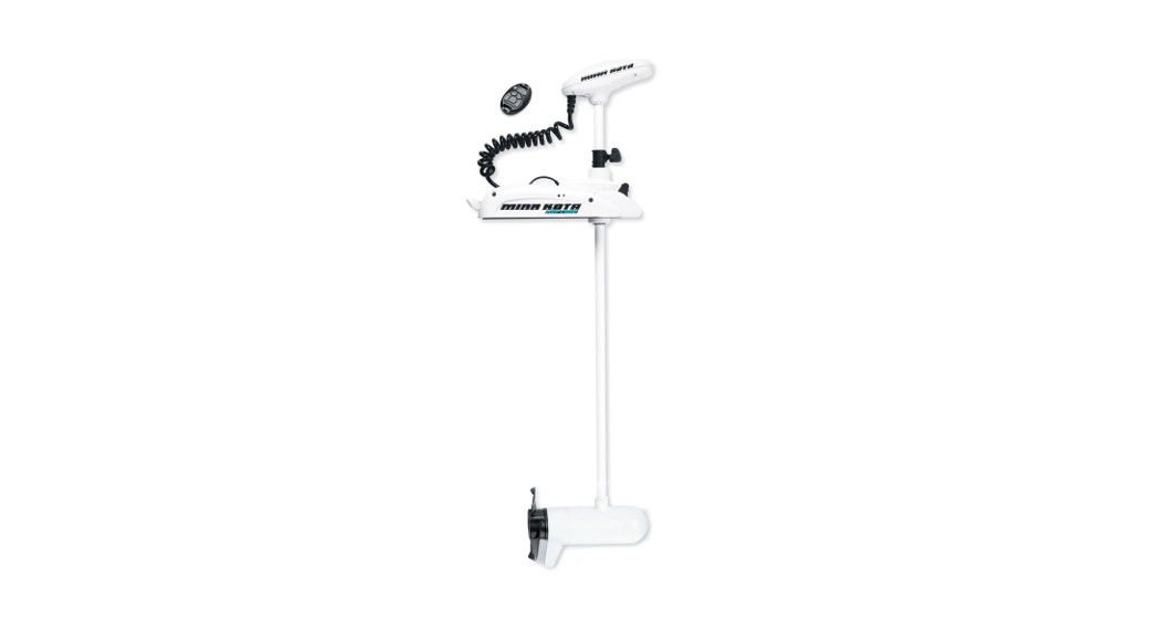
![]() RIPTIDE POWERDRIVEBOW-MOUNT TROLLING MOTORInstallation Instructions
RIPTIDE POWERDRIVEBOW-MOUNT TROLLING MOTORInstallation Instructions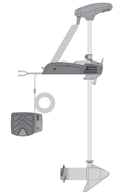
INTRODUCTION
THANK YOUThank you for choosing Minn Kota. We believe that you should spend more time fishing and less time positioning your boat. That’s why we build the smartest, toughest, most intuitive trolling motors on the water. Every aspect of a Minn Kota trolling motor is thought out and rethought until it’s good enough to bear our name. Countless hours of research and testing provide you the Minn Kota advantage that can truly take you “Anywhere. Anytime.” We don’t believe in shortcuts. We are Minn Kota. And we are never done helping you catch more fish.
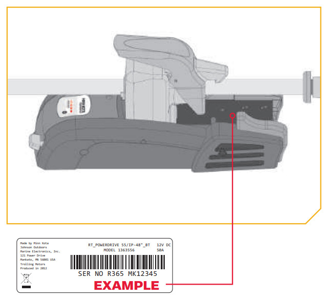
REGISTRATIONRemember to keep your receipt and immediately register your trolling motor. A registration card is included with your motor or you can complete registration on our website atminnkotamotors.com.SERIAL NUMBERYour Minn Kota 11-character serial number is very important. It helps to determine the specific model and year of manufacture. When contacting Consumer Service or registering your product, you will need to know your product’s serial number. We recommend that you write the serial number down so that you have it available for future reference.
NOTICE: The serial number on your Riptide PowerDrive is located inside the mount below the motor rests.
MOTOR INFORMATION (For Consumer Reference Only)Model Serial Number:Controller Serial Number:Purchase Date:Store Where Purchased:
NOTICE: Do not return your Minn Kota motor to your retailer. Your retailer is not authorized to repair or replace this unit. You may obtain service by: calling Minn Kota at (800) 227-6433; returning your motor to the Minn Kota Factory Service Center; sending or taking your motor to any Minn Kota authorized service center. A list of authorized service centers is available on our website, at minnkotamotors.com. Please include proof of purchase, serial number and purchase date for warranty service with any of the above options.
SAFETY CONSIDERATIONS
Please thoroughly read the user manual. Follow all instructions and heed all safety and cautionary notices. Use of this motor is only permitted for persons that have read and understood these user instructions. Minors may use this motor only under adult supervision.![]() WARNINGYou are responsible for the safe and prudent operation of your vessel. We have designed your Minn Kota product to be an accurate and reliable tool that will enhance boat operation and improve your ability to catch fish. This product does not relieve you from the responsibility for safe operation of your boat. You must avoid hazards to navigation and always maintain a permanent watch so you can respond to situations as they develop. You must always be prepared to regain manual control of your boat. Learn to operate your Minn Kota product in an area free from hazards and obstacles.
WARNINGYou are responsible for the safe and prudent operation of your vessel. We have designed your Minn Kota product to be an accurate and reliable tool that will enhance boat operation and improve your ability to catch fish. This product does not relieve you from the responsibility for safe operation of your boat. You must avoid hazards to navigation and always maintain a permanent watch so you can respond to situations as they develop. You must always be prepared to regain manual control of your boat. Learn to operate your Minn Kota product in an area free from hazards and obstacles.![]() WARNINGNever run the motor out of the water, as this may result in injuries from the rotating propeller. The motor should be disconnected from the power source when it is not in use or is off the water. When connecting the power-supply cables of the motor to the battery, ensure that they are not kinked or subject to chafe and route them in such a way that persons cannot trip over them. Before using the motor make sure that the insulation of the power cables is not damaged. Disregarding these safety precautions may result in electric shorts of battery(s) and/or motor. Always disconnect the motor from the battery(s) before cleaning or checking the propeller. Avoid submerging the complete motor as water may enter the lower unit through the control head and shaft. If the motor is used while water is present in the lower unit considerable damage to the motor can occur. This damage will not be covered by warranty.
WARNINGNever run the motor out of the water, as this may result in injuries from the rotating propeller. The motor should be disconnected from the power source when it is not in use or is off the water. When connecting the power-supply cables of the motor to the battery, ensure that they are not kinked or subject to chafe and route them in such a way that persons cannot trip over them. Before using the motor make sure that the insulation of the power cables is not damaged. Disregarding these safety precautions may result in electric shorts of battery(s) and/or motor. Always disconnect the motor from the battery(s) before cleaning or checking the propeller. Avoid submerging the complete motor as water may enter the lower unit through the control head and shaft. If the motor is used while water is present in the lower unit considerable damage to the motor can occur. This damage will not be covered by warranty.![]() WARNINGTake care that neither you nor other persons approach the turning propeller too closely, neither with body parts nor with objects. The motor is powerful and may endanger or injure you or others. While the motor is running watch out for person swimming and for floating objects. Persons whose ability to run the motor or whose reactions are impaired by alcohol, drugs, medication, or other substances are not permitted to use this motor. This motor is not suitable for use in strong currents. The constant noise pressure level of the motor during use is less than 70dB(A). The overall vibration level does not exceed 2,5 m/sec2.
WARNINGTake care that neither you nor other persons approach the turning propeller too closely, neither with body parts nor with objects. The motor is powerful and may endanger or injure you or others. While the motor is running watch out for person swimming and for floating objects. Persons whose ability to run the motor or whose reactions are impaired by alcohol, drugs, medication, or other substances are not permitted to use this motor. This motor is not suitable for use in strong currents. The constant noise pressure level of the motor during use is less than 70dB(A). The overall vibration level does not exceed 2,5 m/sec2.![]() WARNINGWhen stowing or deploying the motor, keep fingers clear of all hinge and pivot points and all moving parts. In the event of an unexpected operation, remove power leads from the battery.
WARNINGWhen stowing or deploying the motor, keep fingers clear of all hinge and pivot points and all moving parts. In the event of an unexpected operation, remove power leads from the battery.![]() WARNING It is recommended to only use Johnson Outdoors approved accessories with your Minn Kota motor. Using non-approved accessories including to mount or control your motor may cause damage, unexpected motor operation, and injury. Be sure to use the product and approved accessories, including remotes, safely and in the manner directed to avoid accidental or unexpected motor operation. Keep all factory-installed parts in place including motor and accessory covers, enclosures, and guards.
WARNING It is recommended to only use Johnson Outdoors approved accessories with your Minn Kota motor. Using non-approved accessories including to mount or control your motor may cause damage, unexpected motor operation, and injury. Be sure to use the product and approved accessories, including remotes, safely and in the manner directed to avoid accidental or unexpected motor operation. Keep all factory-installed parts in place including motor and accessory covers, enclosures, and guards.
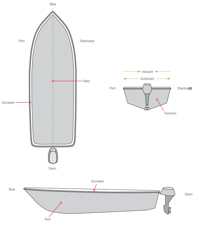
KNOW YOUR BOAT
INSTALLATION
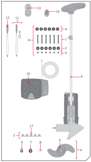
INSTALLING THE RIPTIDE POWERDRIVEYour new Riptide PowerDrive comes with everything you’ll need to directly install it to the boat. This motor can be directly mounted to the boat or coupled with a Minn Kota quick release bracket for ease of mounting and removal. For installation with a quick-release bracket, refer to the installation instructions provided with the bracket. For compatible quick-release mounting brackets and to locate your nearest dealer, visit minnkotamotors.com. To install the motor directly to the boat, please follow the instructions provided in this manual. Please review the parts list, mounting considerations, and tools needed for installation prior to getting started. For additional product support, please visit minnkotamotors.com.INSTALLATION PARTS LIST
| Item /Assembly | Part # | Description | Qty. |
| A | 2994864 | BAG ASSEMBLY – (BOLT, NUT, WASHERS) | 1 |
| 1 | 2263462 | BOLT-MOUNTING-1/4X2 W/STG | 6 |
| 2 | 2261713 | WASHER-1/4 | 6 |
| 3 | 2263103 | NUT NYLOK 1/4-20 MTG | 6 |
| 4 | 2301720 | WASHER-MOUNTING RUBBER | 6 |
| U | 1378131 | PROP IND 2091160 (WDLS WDGII) | 1 |
| 5 | 2091160 | PROP-WW2 (3 5/8″) REAMED | 1 |
| 6 | 2151726 | WASHER-5/16 SS | 1 |
| 7 | 2053101 | NUT-PROP,NYLOC (MED) 5/16 SS | 1 |
| 8 | 2092600 | PIN-DRIVE 1.06″ LG SS | 1 |
| 9 | ✖ | MOTOR ASSEMBLY | 1 |
| 10 | 2994728 | FOOT PEDAL ASSEMBLY, PD | 1 |
| 11 | 2390800 ♦ | LANYARD, REMOTE W/ CARABINER | 1 |
| 12 | 2390801 • | LANYARD, REMOTE *COPILOT* | 1 |
| 13 | 2994075 ♦ | REMOTE ASY, PILOT | 1 |
| 14 | 2994020 • | TRANSMIT, ASY, PD/AP COMPLETE | 1 |
^ |
2397106 | MANUAL, QUICK REF., iPILOT 1.6 | 1 |
^ |
2317123 | MANUAL-INSTALL GUIDE, POWERDRIVE | 1 |
| Z | 2994859 | BAG ASY-TERROVA/V2,RUB.BUMPERS | 1 |
| 17 | 2325110 | PAD, FOOT PEDAL PD | 5 |
^ Not shown on Parts Diagram.✖ This part is included in an assembly and cannot be ordered individually.♦ Only available with models factory installed with i-Pilot or i-Pilot Link.•Only available with models factory installed with CoPilot.
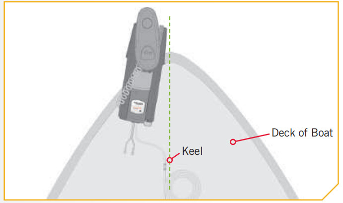
MOUNTING CONSIDERATIONSIt is recommended that the motor be mounted as close to the centerline of the boat as possible. Make sure the area under the mounting location is clear to drill holes and install nuts and washers. Make sure the motor rest is positioned far enough beyond the edge of the boat. The motor must not encounter any obstructions as it is lowered into the water or raised into the boat when stowed and deployed. Consider a quick release or adapter bracket with the installation of your motor. To view a list of accessories, please visit minnkotamotors.com.
 View accessories available for yourtrolling motor at minnkotamotors.com.
HTTP://DELIVR.COM/2M9WS-QR
TOOLS AND RESOURCES REQUIRED
- #3 and #2 Phillips Screw Driver
- Drill
- 9/32” Drill Bit
- 7/16” Box End Wrench
- A second person to help with the installation
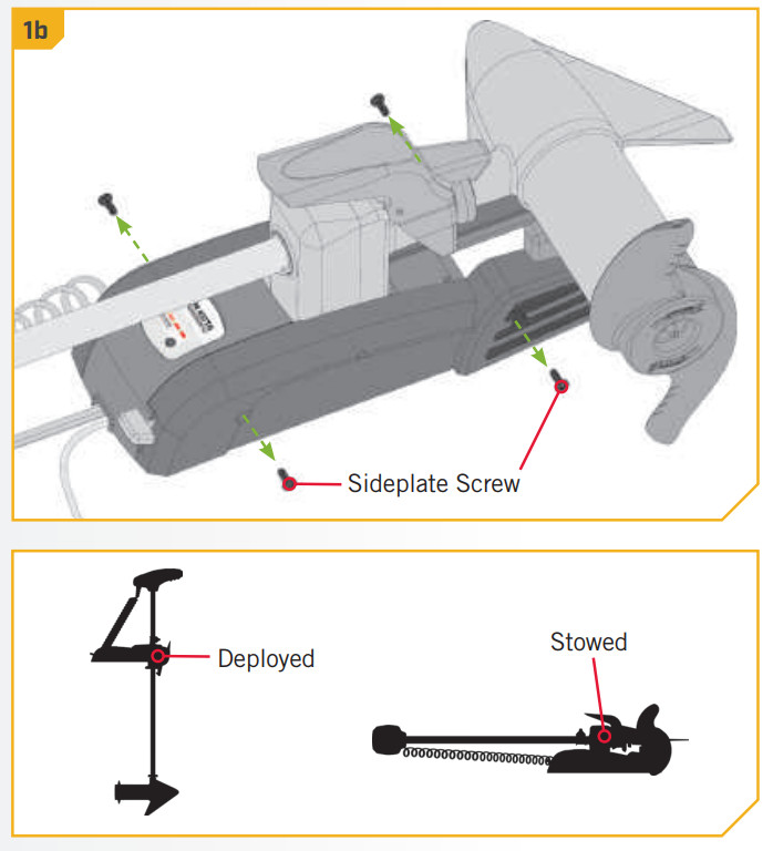
1a. Place the mount on an elevated, level surface such as a workbench or the tailgate of a pickup. The motor, as removed from the box, should be in the stowed position.b. Remove the four side plate screws using a #3 or #2 Phillips screwdriver. Two of these screws will be located on each side of the mount.NOTICE: This motor weighs approximately 30 lbs. We recommend having a second person help with the installation.
2
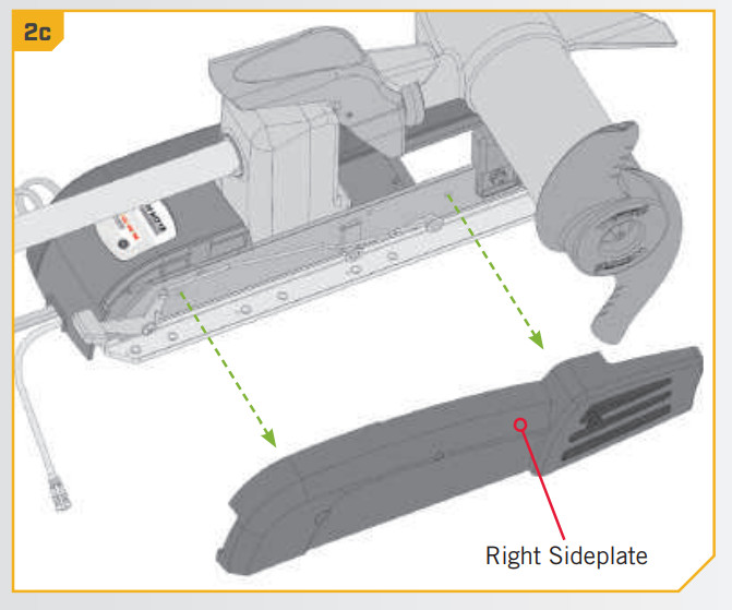
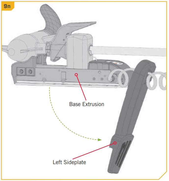
c. Remove the Right Sideplate.d. Swing the Left Sideplate out and away from the Base Extrusion.

3e. Make sure that the Power Cables from the battery are disconnected, or that the breaker if equipped, is “off”. 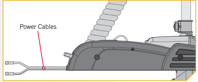
![]() WARNING Make sure the motor is mounted on a level surface and is not connected to a power source.
WARNING Make sure the motor is mounted on a level surface and is not connected to a power source.
4f. Place the mount as close to the centerline or keel of the boat as possible. The motor can be installed on either the Port or Starboard side of the boat based on personal preference. Check placement with the motor in the stowed and deployed positions. Review the mounting considerations at the beginning of the installation.
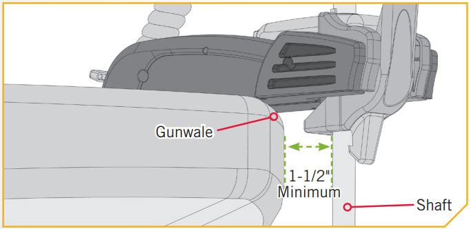
5ITEM(S) NEEDED #4 x 6g. When the motor is in the deployed position, make sure that the Shaft is 1-1/2″ out past the Gunwale of the boat. The lower unit, when stowed and deployed must not encounter any obstructions. h. Check to be sure that the mount is level. Use the Rubber Washers were provided to create a level surface if necessary.
6
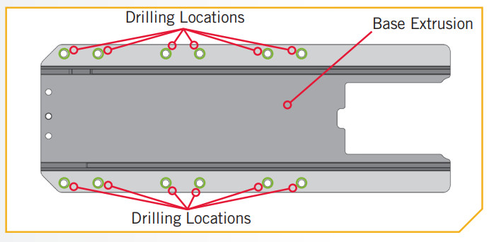
i. It is recommended to mark at least 6 of the 12 holes in the Base Extrusion and to have a minimum of two bolts on each side that are located the farthest apart. Ideal installation would allow for 6 bolts to be used, with a minimum of 4.j. Drill through the deck of the boat using a 9/32″ Drill Bit on the marked locations.
7ITEM(S) NEEDED#4 x 6 /#1 x 6k. Put a 1/4-20 x 3-1/2″ (Item #1) screw in each of the drilled locations. The screw should pass through the Base Extrusion and the boat deck. If the rubber washers (Item #4) are used, they should sit between the Base Extrusion and boat deck. Make sure to secure the motor with screws on each side of the Base Extrusion.
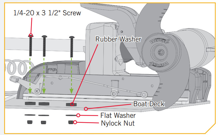
8ITEM(S) NEEDED#2 x 6/ #3 x 6l. Place a Flat Washer (Item #2) and then a Nylock Nut (Item #3) at the end of each screw as shown and secure. Make sure all hardware is secure.
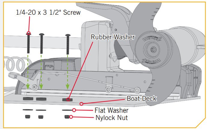
NOTICE: To prevent seizing of the stainless steel hardware, do not use high-speed installation tools. Wetting the screws or applying an anti-seize may help prevent seizing.
9
m. Replace the Right Sideplate.n. Swing the Left Sideplate back into its correct position on the Base Extrusion.

10o. Replace the four side plate screws using a #3 or #2 Phillips screwdriver. Two of these screws will be located on each side of the mount.

11

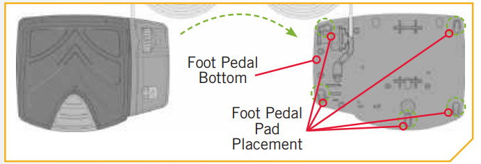
p. Take the Foot Pedal (Item #10) and turn it over. Put a Foot Pedal Pad (Item #17) in each of the pad locations.NOTICE: The pads are recommended when using the Foot Pedal on non-carpeted surfaces.
Installing the Prop
1
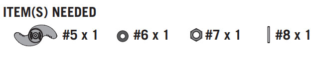
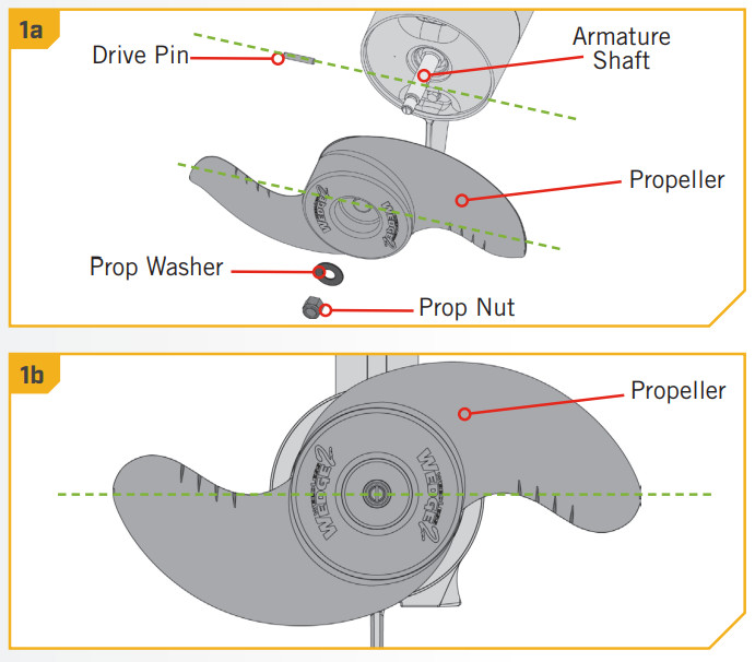
![]() CAUTIONDisconnect the motor from the battery before beginning any prop work or maintenance.a. Take the Drive Pin (Item #8) and slide it through the Hole in the Armature Shaft. Position the Drive Pin horizontal by grasping the Armature Shaft and rotating it with the Drive Pin in place.b. Align the Propeller (Item #5) so it is also horizontal and parallel with the Drive Pin. Slide the Propeller onto the Armature Shaft and Drive Pin until it is seated against the lower unit.c. Install the Prop Washer (Item #6) and the Prop Nut (Item #7) onto the end of the Armature Shaft.
CAUTIONDisconnect the motor from the battery before beginning any prop work or maintenance.a. Take the Drive Pin (Item #8) and slide it through the Hole in the Armature Shaft. Position the Drive Pin horizontal by grasping the Armature Shaft and rotating it with the Drive Pin in place.b. Align the Propeller (Item #5) so it is also horizontal and parallel with the Drive Pin. Slide the Propeller onto the Armature Shaft and Drive Pin until it is seated against the lower unit.c. Install the Prop Washer (Item #6) and the Prop Nut (Item #7) onto the end of the Armature Shaft.
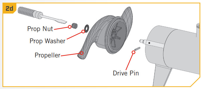
2d. Holding the end of the Armature Shaft with a Flat Blade Screwdriver, tighten the Prop Nut with a 9/16″ Open End Wrench.e. Tighten the Prop Nut 1/4 turn past snug to 25-35 in-lbs.
![]() CAUTIONDo not overtighten as this can damage the prop.
CAUTIONDo not overtighten as this can damage the prop.
BATTERY & WIRING INSTALLATION
BOAT RIGGING & PRODUCT INSTALLATIONFor safety and compliance reasons, we recommend that you follow American Boat and Yacht Council (ABYC) standards when rigging your boat. Altering boat wiring should be completed by a qualified marine technician. The following specifications are for general guidelines only:![]() CAUTIONThese guidelines apply to general rigging to support your Minn Kota motor. Powering multiple motors or additional electrical devices from the same power circuit may impact the recommended conductor gauge and circuit breaker size. If you are using wire longer than that provided with your unit, follow the conductor gauge and circuit breaker sizing table below. If your wire extension length is more than 25 feet, we recommend that you contact a qualified marine technician.
CAUTIONThese guidelines apply to general rigging to support your Minn Kota motor. Powering multiple motors or additional electrical devices from the same power circuit may impact the recommended conductor gauge and circuit breaker size. If you are using wire longer than that provided with your unit, follow the conductor gauge and circuit breaker sizing table below. If your wire extension length is more than 25 feet, we recommend that you contact a qualified marine technician.![]() CAUTIONAn over-current protection device (circuit breaker or fuse) must be used. Coast Guard requirements dictate that each ungrounded current-carrying conductor must be protected by a manually reset, trip-free circuit breaker or fuse. The type (voltage and current rating) of the fuse or circuit breaker must be sized accordingly to the trolling motor used. The table below gives recommended guidelines for circuit breaker sizing.CONDUCTOR GAUGE AND CIRCUIT BREAKER SIZING TABLE This conductor and circuit breaker sizing table is only valid for the following assumptions:
CAUTIONAn over-current protection device (circuit breaker or fuse) must be used. Coast Guard requirements dictate that each ungrounded current-carrying conductor must be protected by a manually reset, trip-free circuit breaker or fuse. The type (voltage and current rating) of the fuse or circuit breaker must be sized accordingly to the trolling motor used. The table below gives recommended guidelines for circuit breaker sizing.CONDUCTOR GAUGE AND CIRCUIT BREAKER SIZING TABLE This conductor and circuit breaker sizing table is only valid for the following assumptions:
- No more than 2 conductors are bundled together inside of a sheath or conduit outside of engine spaces.
- Each conductor has 105° C temp-rated insulation.
- No more than 5% voltage drop allowed at full motor power based on published product power requirements.
| Motor Thrust I Model | MaxAmp Draw | Circuit Breaker | 5 feet | 10 feet | VireExtension Length15 feet | 20 feet | 25 feet |
| 30 W. | 30 | 50 Amp @ 12 VDC | 10 AWG | 10 AWG | 8 AWG | 6 AWG | 4 AWG |
| 40 lb., 45 lb. | 42 | 10 AWG | 8 AWG | 6 AWG | 4 AWG | 4 AWG | |
| 50 lb., 55 lb. | 50 | 60 Amp @ 12 VDC | 8 AWG | 6 AWG | 4 AWG | 4 AWG | 2 AWG |
| 701b. | 42 | 50 Amp @ 24 VDC | 10 AWG | 10 AWG | 8 AWG | 8 AWG | 6 AWG |
| 801b. | 56 | 60 Amp @ 24 VDC | 8 AWG | 8 AWG | 8 AWG | 6 AWG | 6 AWG |
| 1011b. | 46 | 50 Amp @ 36 VDC | 8 AWG | 8 AWG | 8 AWG | 8 AWG | 8 AWG |
| Engine Mount 101 | 50 | 60 Amp @ 36 VDC | 8 AWG | 8 AWG | 8 AWG | 8 AWG | 8 AWG |
| 1121b. | 52 | 60 Amp @ 36 VDC | 8 AWG | 8 AWG | 8 AWG | 8 AWG | 8 AWG |
| Engine Mount 160 | 116 | (2) x 60 Amp @ 24 VDC | 6 AWG | 6 AWG | 4 AWG | 2 AWG | 2 AWG |
| E-Drive | 40 | 50 Amp @ 48 VDC | 10 AWG | 10 AWG | 10 AWG | 10 AWG | 10 AWG |
NOTICE: Wire Extension Length refers to the distance from the batteries to the trolling motor leads. Consult the website for available thrust options. Maximum Amp Draw values only occur intermittently during select conditions and should not be used as continuous amp load ratings.
SELECTING THE CORRECT BATTERIES
The motor will operate with any lead-acid, deep cycle marine 12-volt battery/batteries. For best results, use a deep cycle, marine battery with at least a 105 amp-hour rating. Maintain battery at full charge. Proper care will ensure having battery power when you need it, and will significantly improve the battery life. Failure to recharge lead-acid batteries (within 12-24 hours) is the leading cause of premature battery failure. Use a multi-stage charger to avoid overcharging. We offer a wide selection of chargers to fit your charging needs. If you are using a crank battery to start a gasoline outboard, we recommend that you use a separate deep cycle marine battery/ batteries for your Minn Kota trolling motor. For more information on battery selection and rigging, please visit minnkotamotors.com.Minn Kota trolling motors can run on Lithium-Ion batteries. However, they are specifically designed to run on traditional lead-acid batteries (flooded, AMG or GEL). Lithium-Ion batteries maintian higher voltages for longer periods of time than lead-acid. Therefore, running a Minn Kota trolling motor at speeds higher than 85% for a prolonged period could cause permanent damage to the motor.
![]() WARNINGNever connect the (+) and the (–) terminals of the same battery together. Take care that no metal object can fall onto the battery short the terminals. This would immediately lead to short and extreme fire danger.
WARNINGNever connect the (+) and the (–) terminals of the same battery together. Take care that no metal object can fall onto the battery short the terminals. This would immediately lead to short and extreme fire danger.![]() CAUTIONRefer to “Conductor Gauge and Circuit Breaker Sizing Table” in the previous section to find the appropriate circuit breaker or fuse for your motors. For motors requiring a 60-amp breaker, the Minn Kota MKR-19 60-amp circuit breaker is recommended.
CAUTIONRefer to “Conductor Gauge and Circuit Breaker Sizing Table” in the previous section to find the appropriate circuit breaker or fuse for your motors. For motors requiring a 60-amp breaker, the Minn Kota MKR-19 60-amp circuit breaker is recommended.![]() CAUTIONPlease read the following information before connecting your motor to your batteries in order to avoid damaging your motor and/or voiding your warranty.
CAUTIONPlease read the following information before connecting your motor to your batteries in order to avoid damaging your motor and/or voiding your warranty.
ADDITIONAL CONSIDERATIONSUsing DC or Alternator ChargersYour Minn Kota trolling motor may be designed with an internal bonding wire to reduce sonar interference. Most alternator charging systems do not account for this bonding wire and connect the negative posts of the trolling motor batteries to the negative posts of the crank/starting battery. These external connections can damage connected electronics and the electrical system of your trolling motor, voiding your warranty. Review your charger’s manual carefully or consult the manufacturer prior to use to ensure your charger is compatible.Minn Kota recommends using Minn Kota brand chargers to recharge the batteries connected to your Minn Kota trolling motor, as they have been engineered to work with motors that include a bonding wire.Additional Accessories Connected to Trolling Motor Batteries Significant damage to your Minn Kota motor, your boat electronics, and your boat can occur if incorrect connections are made between your trolling motor batteries and other battery systems. Minn Kota recommends using an exclusive battery system for your trolling motor. Where possible, accessories should be connected to a separate battery system. Radios and sonar units should not be connected to any trolling motor battery systems as interference from the trolling motor is unavoidable. If connecting any additional accessories to any trolling motor battery system, or making connections between the trolling motor batteries and other battery systems on the boat, be sure to carefully observe the information below.
CONNECTING THE BATTERIES
The negative (-) connection must be connected to the negative terminal of the same battery that the trolling motor negative lead connects to. In the diagrams below this battery s labeled “Low Side” Battery. Connecting to any other trolling motor battery will input positive voltage into the “ground” of that accessory, which can cause excess corrosion. Any damage caused by incorrect connections between battery systems will not be covered under warranty.Automatic Jump Start Systems and Selector SwitchesAutomatic jump start systems and selector switches tie the negatives of the connected batteries together. Connecting these systems to the “High Side” Battery or “Middle” Battery in the diagrams below and will cause significant damage to your trolling motor and electronics. The only trolling motor battery that is safe to connect to one of these systems is the “Low Side” Battery.
NOTICE: The internal bonding wire is equipped with a 3 amp fuse. Improper connections described above carrying in excess of 3 amps will blow this fuse and no further damage will be exhibited. If this occurs, RF interference from the trolling motor affecting sonar units and other electronics will be more significant. If the fuse is blown the wiring error should be found and addressed prior to replacing the fuse. The replacement fuse should be 3 amps or less. An intact fuse does not imply correct rigging; significantdamage can be done by incorrect wiring without approaching 3 amps of current.12 Volt Systems
- Make sure that the motor is switched off (speed selector on “OFF” or “0”).
- Connect positive ( + ) red lead to positive ( + ) battery terminal.
- Connect negative ( – ) black lead to negative ( – ) battery terminal
![]() WARNINGFor safety reasons do not switch the motor on until the propeller is in the water. If installing a lead wire plug, observe proper polarity and follow instructions in your boat owner’s manual.
WARNINGFor safety reasons do not switch the motor on until the propeller is in the water. If installing a lead wire plug, observe proper polarity and follow instructions in your boat owner’s manual.![]() WARNING
WARNING
- For safety reasons, disconnect the motor from the battery or batteries when the motor is not in use or while the battery/batteries are being charged.
- Improper wiring of 24/36 volt systems could cause battery explosion.
- Keep lead wire wing nut connections tight and solid to battery terminals.
- Locate the battery in a ventilated compartment.
CONNECTING THE BATTERIES IN SERIES
CONNECTING THE BATTERIES IN SERIES (IF REQUIRED FOR YOUR MOTOR)24 Volt SystemsTwo 12 volt batteries are required. The batteries must be wired in series, only as directed in a wiring diagram, to provide 24 volts.
- Make sure that the motor is switched off (speed selector on “0”).
- Connect a connector cable to the positive ( + ) terminal of battery 1 and to the negative ( – ) terminal of battery 2.
- Connect positive ( + ) red motor lead to positive ( + ) terminal on battery 2.
- Connect negative ( – ) black motor lead to negative ( – ) the terminal of battery 1.

![]() WARNINGFor safety reasons do not switch the motor on until the propeller is in the water. If installing a lead wire plug, observe proper polarity and follow instructions in your boat owner’s manual.
WARNINGFor safety reasons do not switch the motor on until the propeller is in the water. If installing a lead wire plug, observe proper polarity and follow instructions in your boat owner’s manual.![]() WARNING
WARNING
- For safety reasons, disconnect the motor from the battery or batteries when the motor is not in use or while the battery/batteries are being charged.
- Improper wiring of 24/36 volt systems could cause battery explosion.
- Keep lead wire wing nut connections tight and solid to battery terminals.
- Locate the battery in a ventilated compartment.
This completes the installation of your Riptide PowerDrive. A Complete Owner’s Manual can be downloaded at minnkotamotors.com.
RECOMMENDED ACCESSORIES
ON-BOARD & PORTABLE BATTERY CHARGERSStop buying new batteries and start taking care of the ones you’ve got. Many chargers can actually damage your battery over time – creating shorter run times and shorter overall life. Digitally controlled Minn Kota chargers are designed to provide the fastest charge that protects and extends battery life.

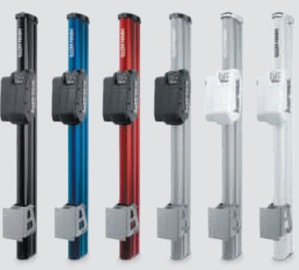
TALON SHALLOW WATER ANCHORIntroducing the all-new, sleek redesigned Talon. Talon is the only shallow water anchor with up to 15’ of anchoring depth, multiple anchoring modes, and control from the bow, transom, console, remote or mobile device.
 BUILT-IN WORK LIGHTLets you tie lines and work from the transom any time of day — or night. Includes both white and blue LED lights with three brightness settings.
 BLUETOOTH®CONNECTIVITYLet’s you control Talon from your mobile device and easily update it. Also opens up communication to other control options.
 UP TO 15’ DEEPControl more water and catch more fish with the first 15’ shallow water anchor.
MORE CONTROL OPTIONS

- Control Panel
- Wireless Remote
- Mobile App
- Wireless Foot Switch
- Humminbird® Connectivity
- i-Pilot ® & i-Pilot Link ™Remote
MINN KOTA ACCESSORIES
We offer a wide variety of trolling motor accessories, including:
- 60-Amp Circuit Breaker
- Mounting Brackets
- Stabilizer Kits
- Extension Handles
- Battery Connectors
- Battery Boxes
- Quick Connect Plugs
![]()

| Minn Kota Consumer & Technical ServiceJohnson Outdoors Marine Electronics, Inc.PO Box 8129Mankato, MN 56001 | 121 Power DriveMankato, MN 56001Phone (800) 227-6433Fax (800) 527-4464 |
![]()
©2021 Johnson Outdoors Marine Electronics, Inc.All rights reserved.
References
[xyz-ips snippet=”download-snippet”]